Replacing valve guides
WIS 05-2850
Preceding work: Valve guides checked (05-2845).
Basic bore and valve guide in cylinder head
Standard size Repair size Il Standard size Repair size
Basic bore © in cylinder 14.000 – 14.011 14.035 14.210 14.410 head
Outer @ and color coding 14.023 – 14.031 14.023 – 14.030 14.214 — 14.222 14.414 – 14.422 of valve guide grey — green red white 14.044 ~ 14.051 grey — brown
Inlet part no. – 103 050 22 24 103 050 23 24 103 050 24 24
Exhaust part no. – 103 050 27 24 103 050 28 24 103 050 29 24
Overlap 0.012 – 0.031
| Valve guide | Inlet | Exhaust | ||
| wave guide | 8.000 – 8.015 | 9.000 – 9.015 | ||
| Length | 42 | |||
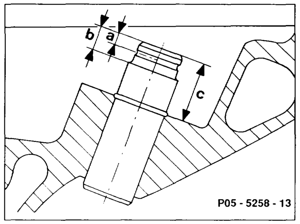
| Size | a b c | 6.3 – 6.6 16.7 – 16.9 | 3.3 | 3.3 6.3 – 6.6 15.9 -— 16.1 |
aie §=RA 05.1123-2850/1
Knocking out vaive guide
B
POS – 5259 – 57
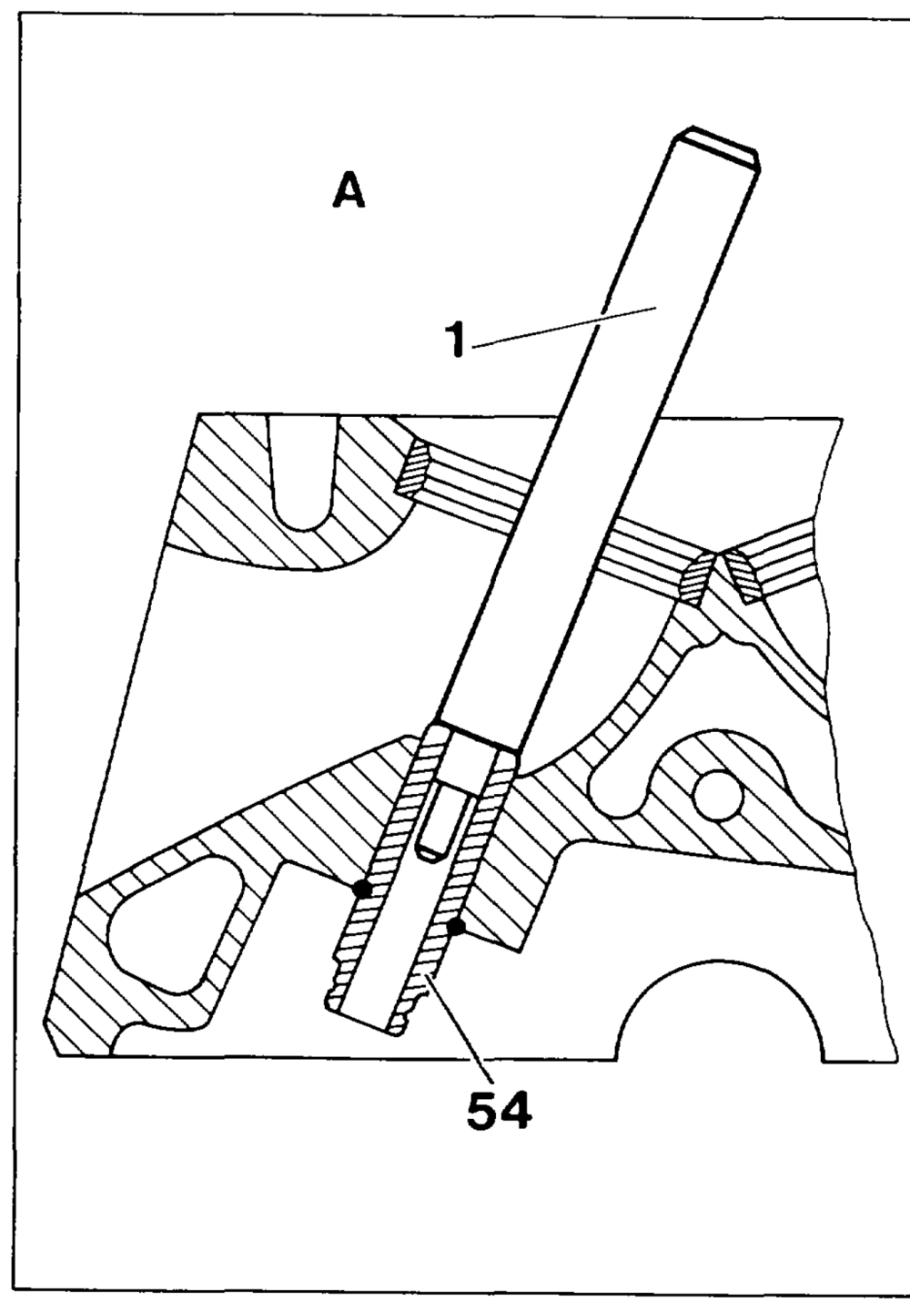
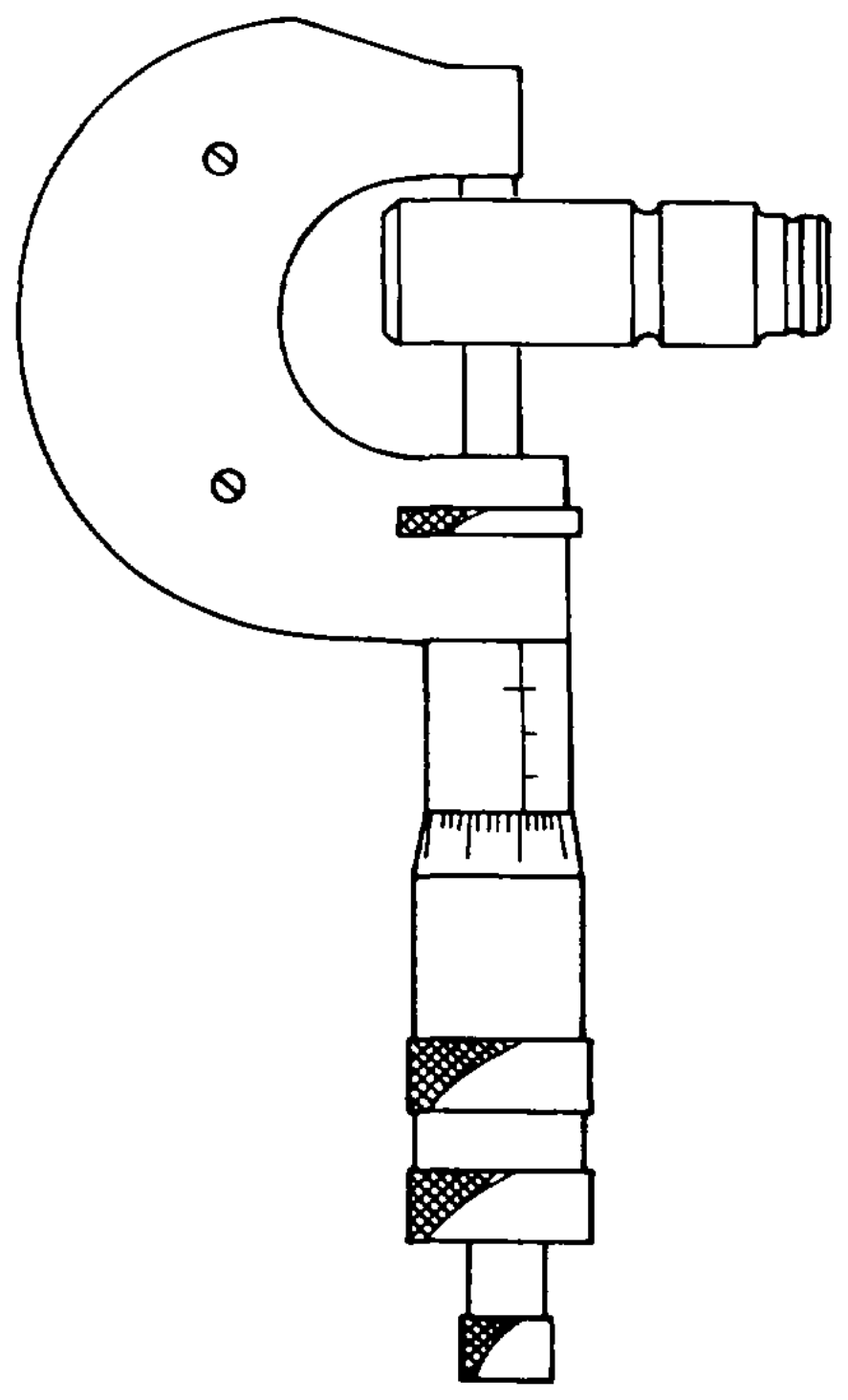
A Valve guide knocked out B Measuring valve guide OD
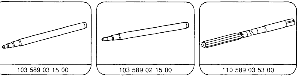
Valve guide (64) …………..2.. 0.00082 knock out from combustion chamber side with drift (1). Inlet drift 8 mm dia. 103 589 03 15 Exhaust drift 9 mm dia. 103 589 02 15
Checking basic bore, matching valve guide
OD measure with a micrometer.
Determine which valve guide is installed, see table. Next larger valve guide match. Basic bore in cylinder head according to matched valve guide ………………0– file standard size or broach repair size I.
aime §=RA 05.1123-2850/2
Standard size
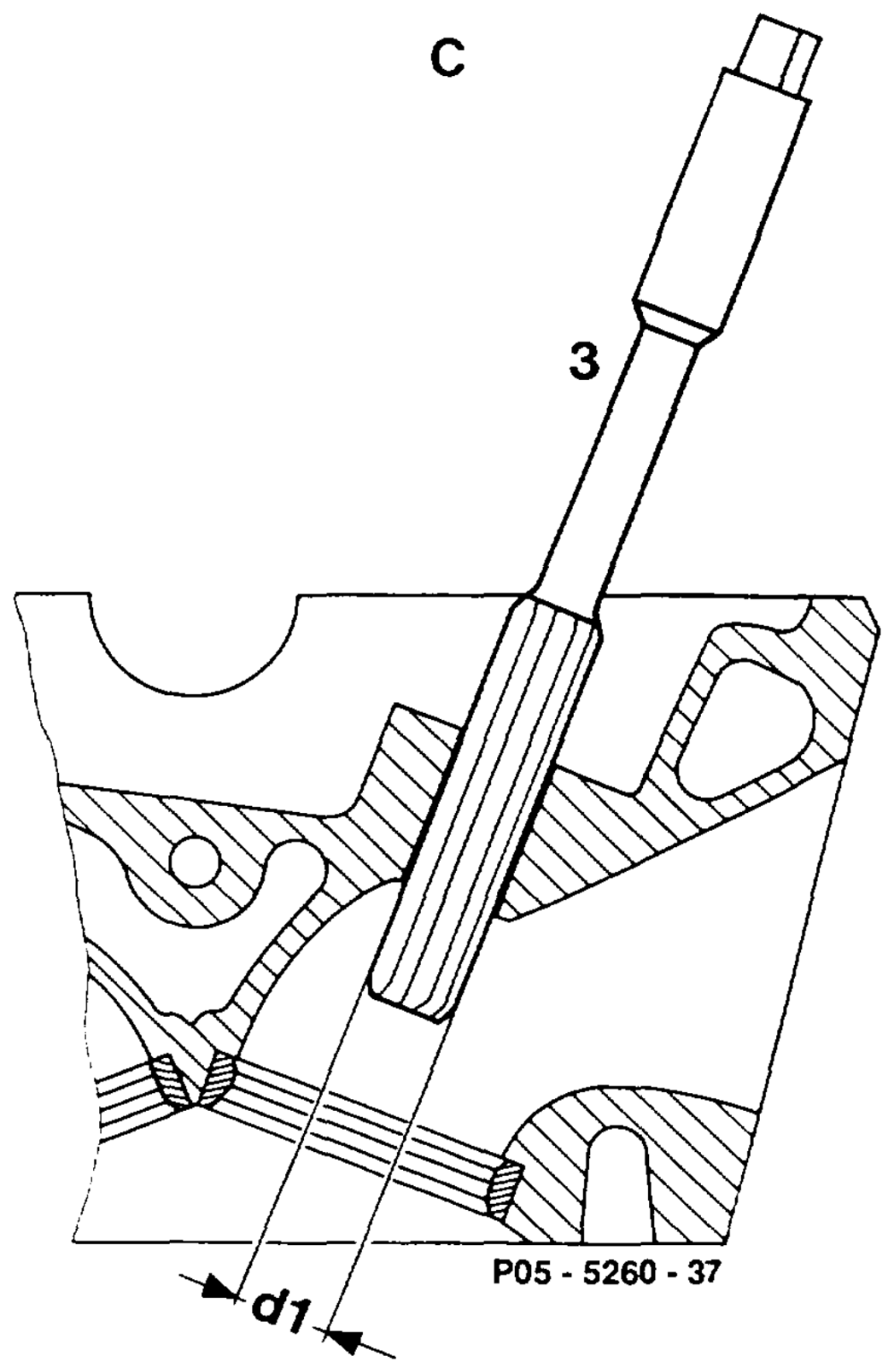
Basic bore ……… ream with reamer. Basic bore ……… ream through with reamer (3) 110 589 03 53 00 dia. 14.035 mm.
Lubricate with petroleum when reaming. do not tilt reamer (3). Apply only slight pressure when reaming and Clean blades of reamer before each reaming operation.
aime =RA 05.1123-2850/3
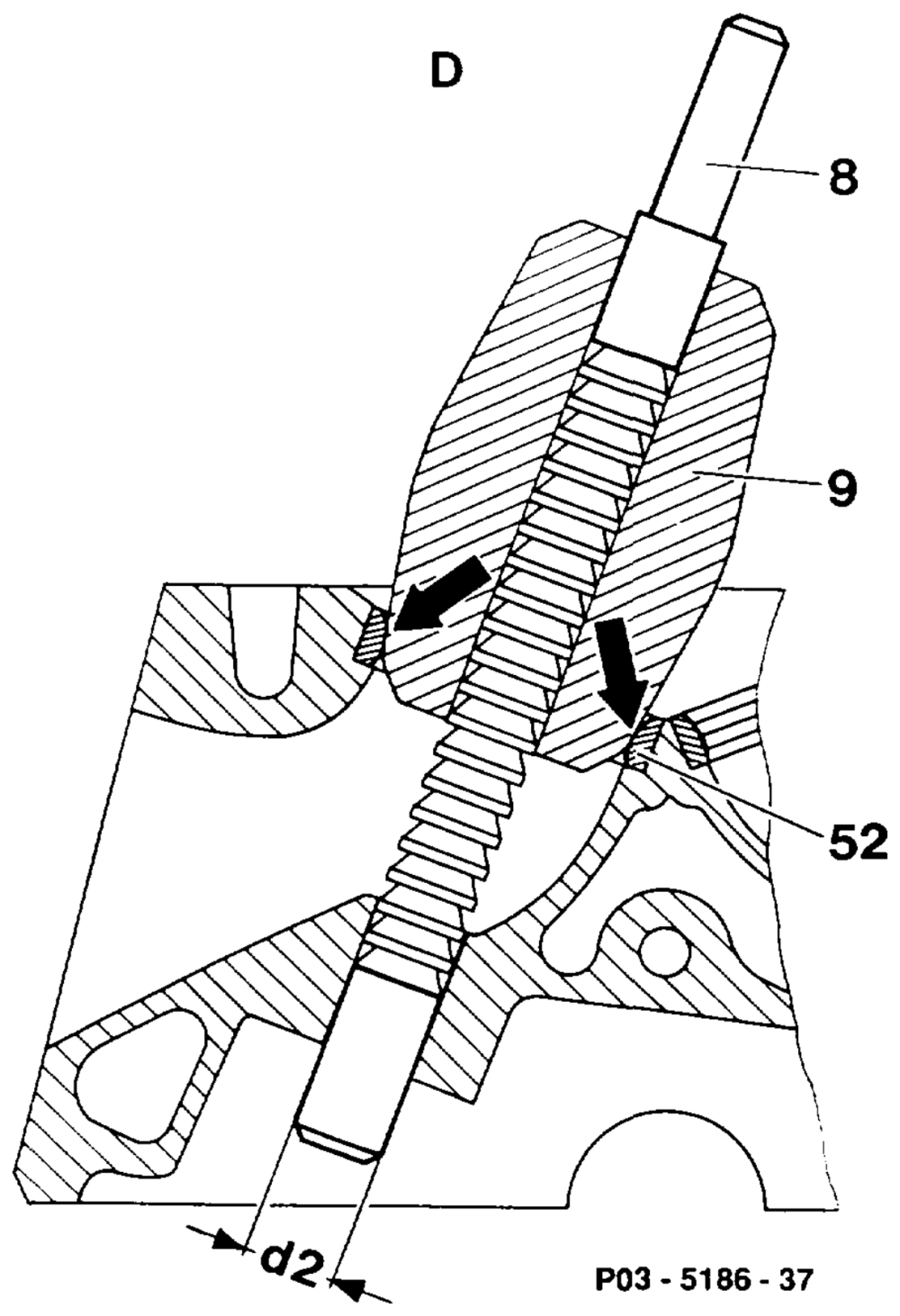
Repair size (broaching basic bore with broaching needle dia. 14.21)
Matching engines – guide sleeves — broaching needles
Engine Valve Valve guide Guide sleeve Page Broaching needle basic bore part no. part no. >woD r>Y> 103.94 103.98 Inlet 14.21 mm 103.94 103.98 Exhaust 14.21 mm – 102 589 00 63 00
remove all carbon deposits. Inside of valve seat rings ………….. Blades of broaching needle (8) ……… clean with plastic brush before each broaching operation. Appropriate guide sleeve (9) ……….. select, see table. Guide sleeve (9), basic bore and broaching needle (8)… ee eee moisten with engine oil. Guide sleeve (9) together with broaching needle (8) …………….. introduce into cylinder head. – 115 589 00 53 00
aie RA 05.1123-2850/4
Broaching needle (8) ……..——eeeeeee insert into basic bore in broaching direction up to first blade.
Fit guide sleeve (9) onto valve seat ring (52) (arrows) and by turning center guide sleeve (9) on valve seat ring (arrows) and broaching needle (8) 2.6… ee ee eee in basic bore.
A Centering must not take place on carbon residues, casting projections, inlet and exhaust passage walls. Broaching needle (8) ………….–00 2 eee press through.
Inserting valve guide, checking ID
57
time §=RA 05.1123-2850/5
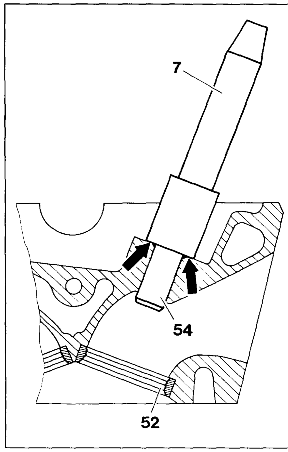
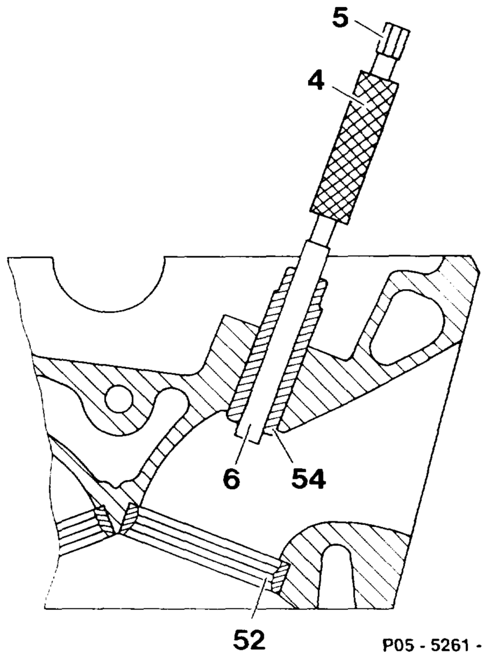
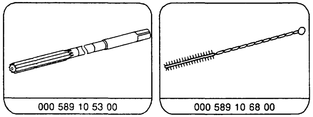
Valve guide (54) ……………….2008supercool, in liquid nitrogen (approx. 3 minutes). If no liquid nitrogen available, …………… heat cylinder head in water bath to approx. 80 °C. Valve guide (54) ………………..008.- knock in with drift (7) as far as stop (arrows). Inlet drift 103 589 00 15 00. Exhaust drift 103 589 01 15 00. Valve guide (54) when cylinder head cooled check if tightly seated. ID of valve guide (54) check with gauging drift (4). Inlet gauging drift 102 589 00 23 00 Exhaust gauging drift 117 589 03 23 00 It must be possible to insert the go side (6) of the gauging drift (4) 0… eee eee fully. If necessary, ream ID ……………2.00with reamer. Inlet reamer 000 589 21 53 00 Exhaust reamer 000 589 10 53 00 Valve seat (52) 0.0… ee ee eee check concentricity, re-work if necessary (05-2910).
Special tools
co
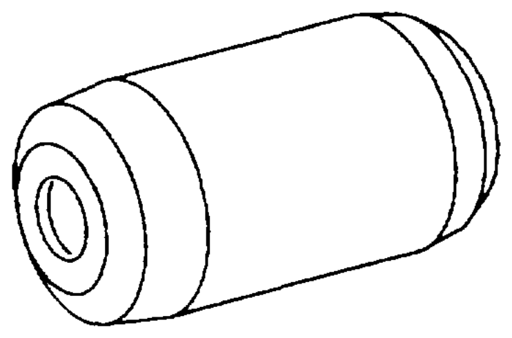
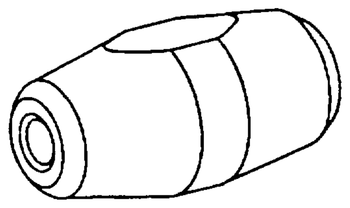
\
\ 102589006300 / \_ 102589 02 63 00 – 102 589 01 63 00
wii §=RA 05.1123-2850/6
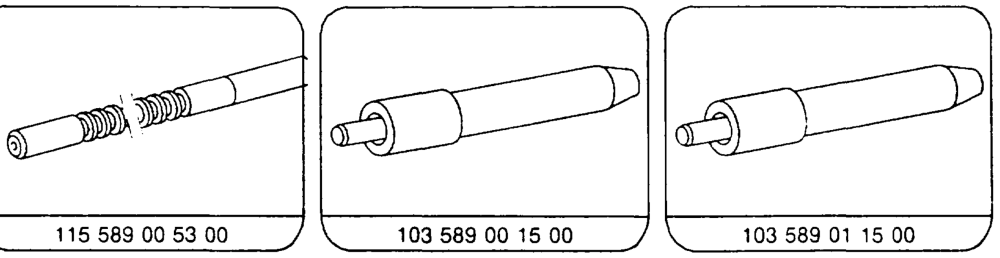
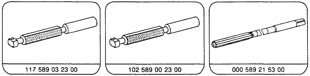
\
Commercially available tool
Cylinder head tensioning device eg. Hunger D-81375 Munchen Order no. 221.60.000 Micrometer 0.25 mm
ite §=RA 05.1123-2850/7
Note Inlet, exhaust valve guides made of improved material.
1st version 2nd version
| Inlet | brass-coloured copper-coloured |
| Exhaust | brass-coloured _ brass-coloured |
Production breakpoint: December 1989
Model Engine Engine end no. manual automatic transmission transmission
124.026 103.940 029502 076413
124.030 103.983 035036 196370 124.050 124.090
124.226 103.943 000508 001192
124.230 103.985 002401 009671 124.290
126.020 103.941 004458 014693
126.024 103.981 007781 106846 126.025
201.029 103.942 016242 041289
«aie RA 05.1123-2850/8