Removing and installing engine
WIS 01-0300
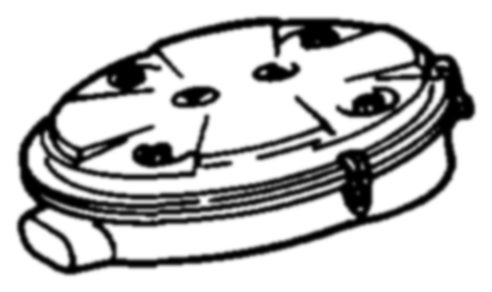
Preceding work: Operation no. of operation texts and work units or standard texts Bottom engine compartment panel removed (Maintenance and flat rates Manual Volume 2, Op. no. 6190). 01-2400, 01-2800 Air cleaner removed (09-1051). Radiator removed (20-4200). Viscous fan coupling removed (20-3120).
A. Model 124 and 124 4MATIC
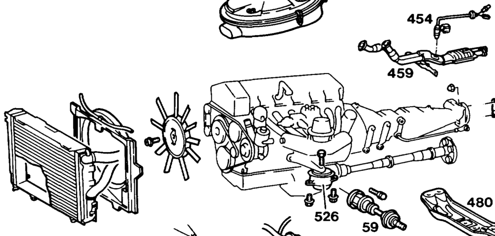
PO1-0104–57
INustration shows Model 124 4MATIC.
Ground cable at battery ………………. disconnect, connect (step 1). If air conditioning fitted ……………000. attach guard plate to condensor, remove poly V-belt and fit on (13-3420) (steps 2 – 3). Power steering pump ………….—-20– extract oil from reservoir, pour in oil to correct level (46-7150) (step 7).
oie RA 01.1113-0300/1
OillineS 22… 0… eee ee ee eee detach, attach (step 8). detach refrigerant compressor (425) with piping If air conditioning fitted group connected, place to the side, attach, 25 Nm (step 9). Hydraulic system, high-pressure expansion hose (4MATIC) 00.0. ccc cece cece eee enes depressurize, move lever on service valve to test position, unscrew and screw on (steps 5 – 6). Fuellines 2… 2… 0.0.0.0 cee eee eee detach and seal, briefly open fuel filler cap before, attach (step 10). detach, attach (30-3402) (step 11). Bowden cable (accelerator control) ……….. Electrical connections and engine wiring detach, attach (steps 12 and 13). harnesS 2… 6. eee ees
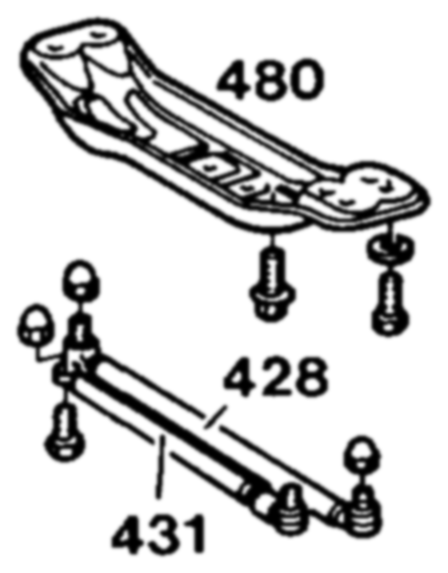
Heating hoses and vacuum lines ………… detach, attach (step 14). Lambda sensor (454) …………….000. remove, install (step 22). Exhaust system and shield above exhaust remove, install (49-7000) (step 23). system Cross bar (4MATIC) ………….0 000006] remove, install 25 Nm (step 24). Propeller shaft (501) at flexible joint ………. detach, attach 45 Nm, renew self-locking nuts (step 25). Clamping nut and intermediate bearing mounting 2… 6 eee eee eee slacken, tighten 35 and 35 Nm (steps 26 and 27). Shift rods on transmission …………….4. detach, attach (steps 31 and 32). Starter lockout switch (automatic transmission) turn locking element, detach connector and fit on (step 32). Hydraulic line for clutch …………….04. unscrew, screw on (step 33). Drag link (428) with steering damper (431) ….. remove and install, renew self-locking nuts and bolts (46-550) (step 34). Left, right front axle shafts (59) (4MATIC) …… detach, attach on inside, 70 Nm, and secure joints with wire (step 35). Engine hoist to suspension lugs …………. attach, detach (step 36). Transmission 1.2.0… 0.00. ee ee eee support (step 38). Guard plate on component compartment wall insert, remove (step 37). remove, install 4MATIC 20 Nm, Model 124 Rear engine support (480) without engine mount 35 Nm (steps 39 and 40). Front engine mounts (526 and 522) left and right 2.0… ee ee eee eee eee unscrew, screw on from below, 4MATIC 20 Nm, Model 124 40 Nm (step 41).
am RA 01.1113-0300/2
raise, lower (step 42). Engine with engine hoist
Installation note
Replace seal at heater feed pipe (engine suspension eye) check. Front and rear engine mounts check. Coolant, oil and fuel hoses adjust cable for control pressure If automatic transmission fitted (27-100). check and adjust Idling check tightening torque. Oil drain plugs adjust to correct level. Oil level in engine and transmission pour in, check anti-corrosion/antifreeze Coolant protection and adjust to correct level (20-0100). bleed (steps 49 to 53). Hydraulic system (4MATIC) read, erase. Fault memory
Note After completing the work, faults stored in the fault memories must be processed (rectified cause) and erased.
See Diagnosis Manual Volume 2: Index 0: connecting and using testers. run and check for leaks.
Special tools
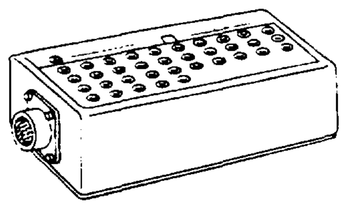
oie RA 01.1113-0300/3 – 124 589 00 21 00
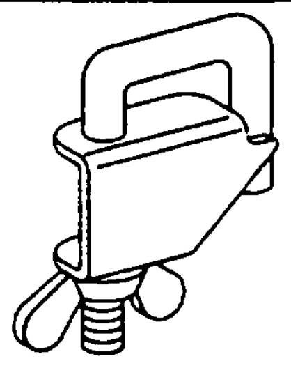
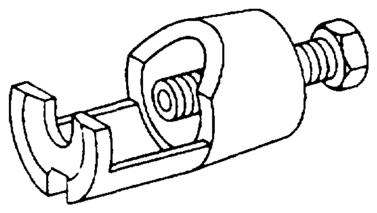
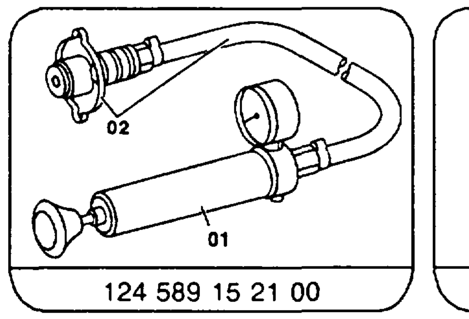
NG 000589403700 /\ – 201 589 14 33 00
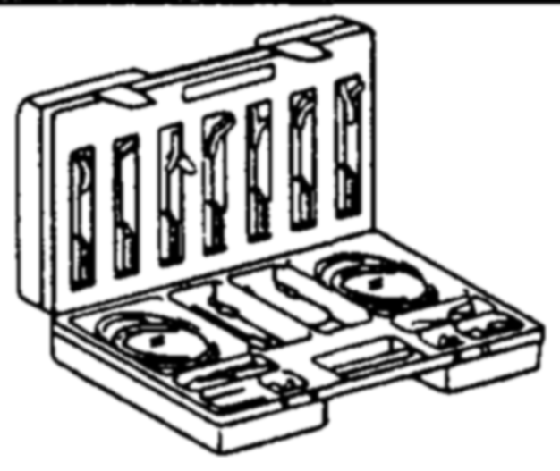
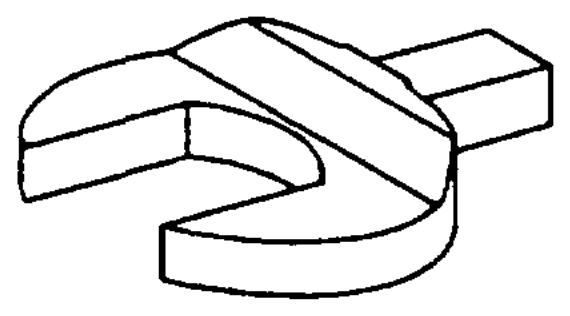
NT
| Commercially available tools and testers | 126589000100 | / | \ 201589009900 / | |
| Designation | Bn | |||
| Engine hoist No. 3188 self-locking | eg. Wilhelm Backer | Herder Str. D-42853 Remscheid | ||
| Anti-corrosion/antifreeze tester Preston-VU-Check | eg. Philipp Gather | D—40822 Mettmann 2 | ||
Shop-made tools
Guard plate for radiator/condensor Dim. approx. 480 x 600 x 1
Metal panel for component compartment wall Dim. approx. 320 x 380 x 1
ee al RA 01.1113-0300/4
Note Remove, install engine with transmission, if 4MATIC fitted with transfer case and front propeller shaft. A4MATIC reconditioned engines are supplied with assembly oil sump. This must be converted (01-3200).
A Do not strike or place a load on lube oil line on transfer case when engine positioned at an angle because this may cause it to leak.
A In the case of engine damage affecting the pistons, valves etc., parts may get in up to just before the catalytic converter or pre-catalytic converter. When exchanging the engine, it is essential to remove these parts otherwise they may be pulsed back into the cylinders as a result of gas vibrations in the exhaust system and again cause engine damage. In addition, these parts may cause mechanical damage to the catalytic converter. In dealing with such engine damage, it is therefore essential to remove these foreign bodies in the exhaust system. Damaged catalytic converters must be replaced.
ine RA 01.1113-0300/5
Removal, installation
1 Detach ground cable at battery.
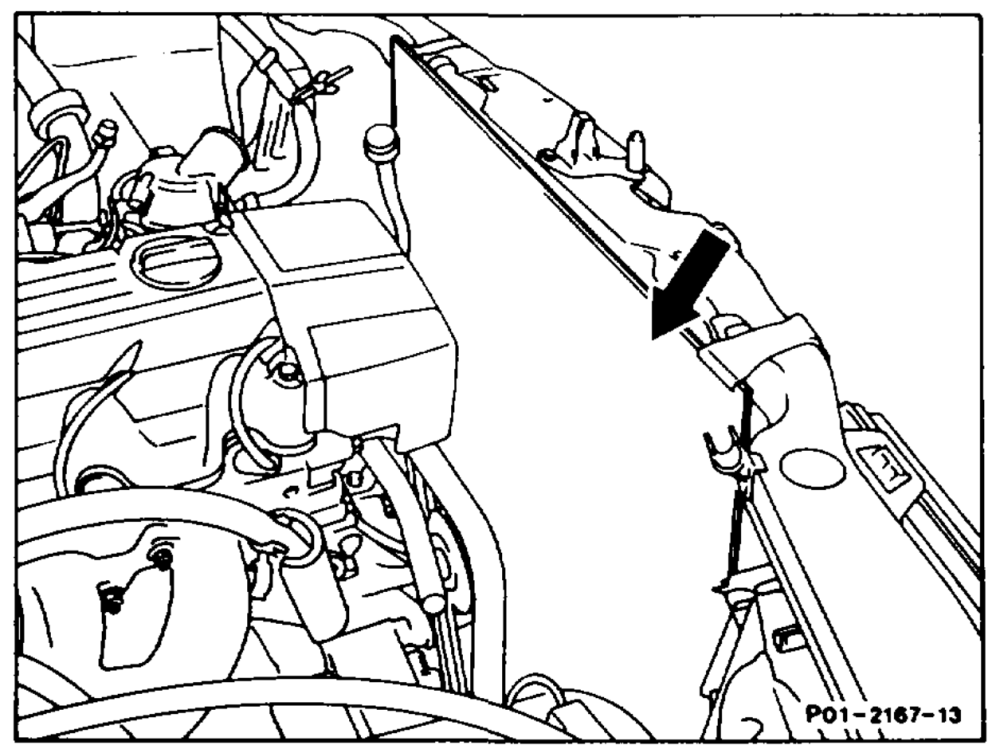
2 If air conditioning fitted: attach guard plate (arrow) to condensor of air conditioning system.
3 If air conditioning fitted: remove poly-V-belt (13-3420).
4MATIC
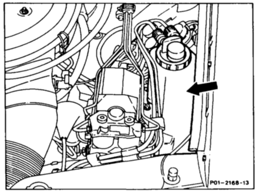
4 Pinch oil hose at bottom of hydraulic oil reservoir (arrow) and detach at power steering pump.
4MATIC
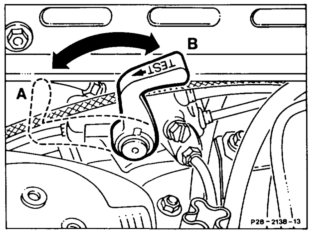
5 Depressurize hydraulic system by moving over lever (test position) on service valve.
A Test position B Operate position
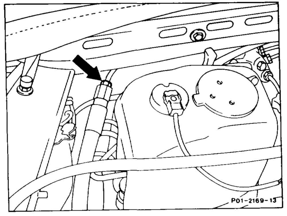
6 Detach screw connection (arrow) at highpressure expansion hose.
am RA 01.1113-0300/6
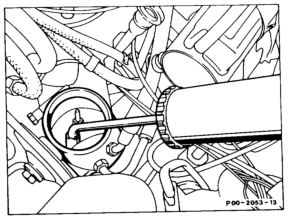
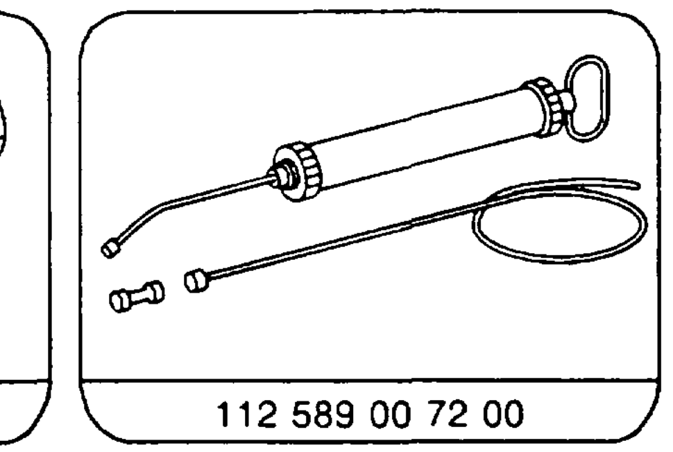
7 €xtract oil from the reservoir of the power steering pump with the priming pump.
Installation note
Bleed pressurized oil pump (32-6300).
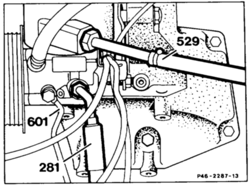
8 Unscrew oil lines (281, 529) to steering gear and oil line (601) for self-levelling suspension at power steering pump.
Installation instruction
Renew seals. Pay attention to tightening torque of highpressure expansion hose (281). Pay attention to tightening torque of return line (529).
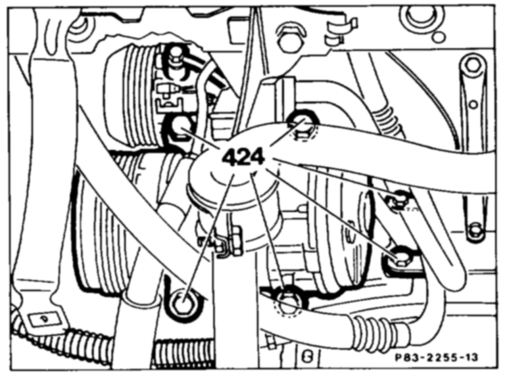
9 Detach refrigerant compressor of air conditioning system from engine. Unscrew bolts (424). Pay attention to tightening torque. Attach refrigerant compressor with pipe group connected at the side in bottom of engine compartment.
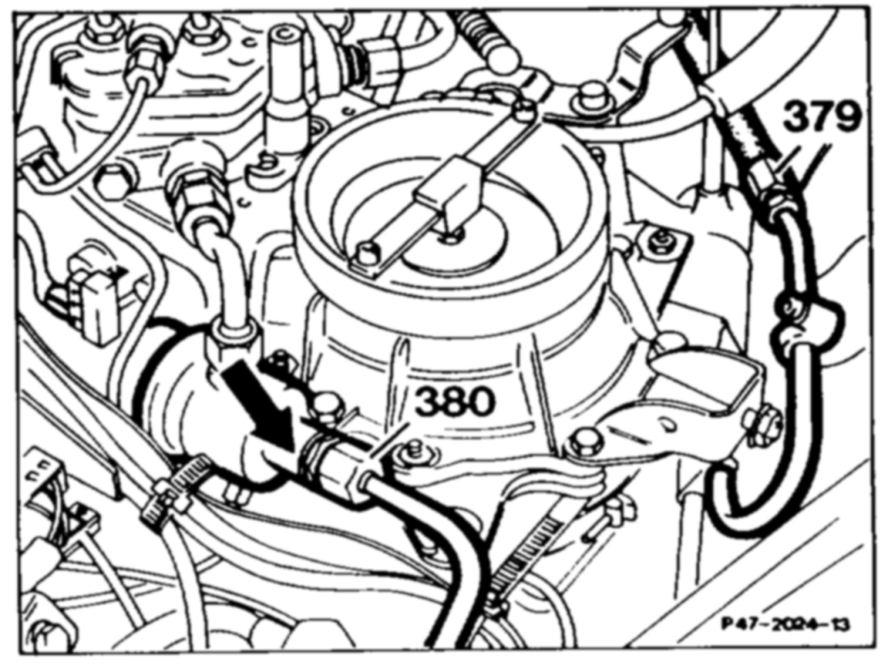
10 Briefly open the fuel filler cap to release the pressure in the fuel tank. Unscrew fuel lines (380, 379). Hold the connection fitting (arrow) when detaching the fuel line (380).
a RA 01.1113-0300/7
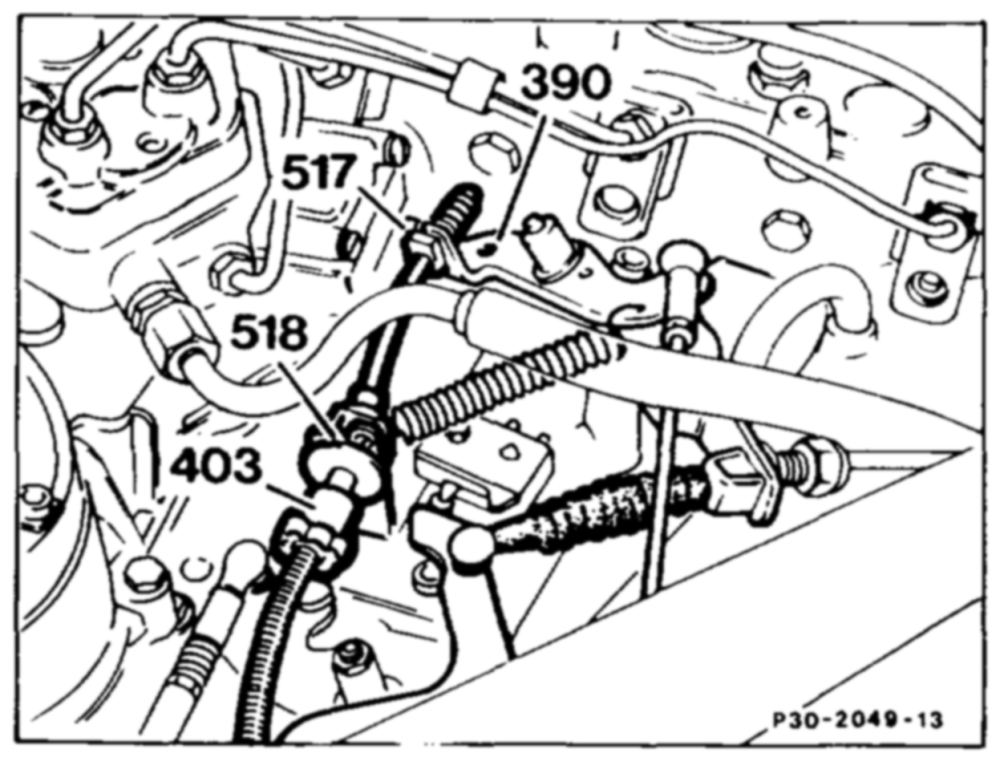
Press plastic guide (517) out of its seat in the fulcrum lever (390) and withdraw Bowden cable (403) through the slot in the fulcrum lever. Compress links of the plastic clip (518) and push clip with the Bowden cable (403) to the rear through the bracket.
Installation instruction
Adjust Bowden cable (30-3402).
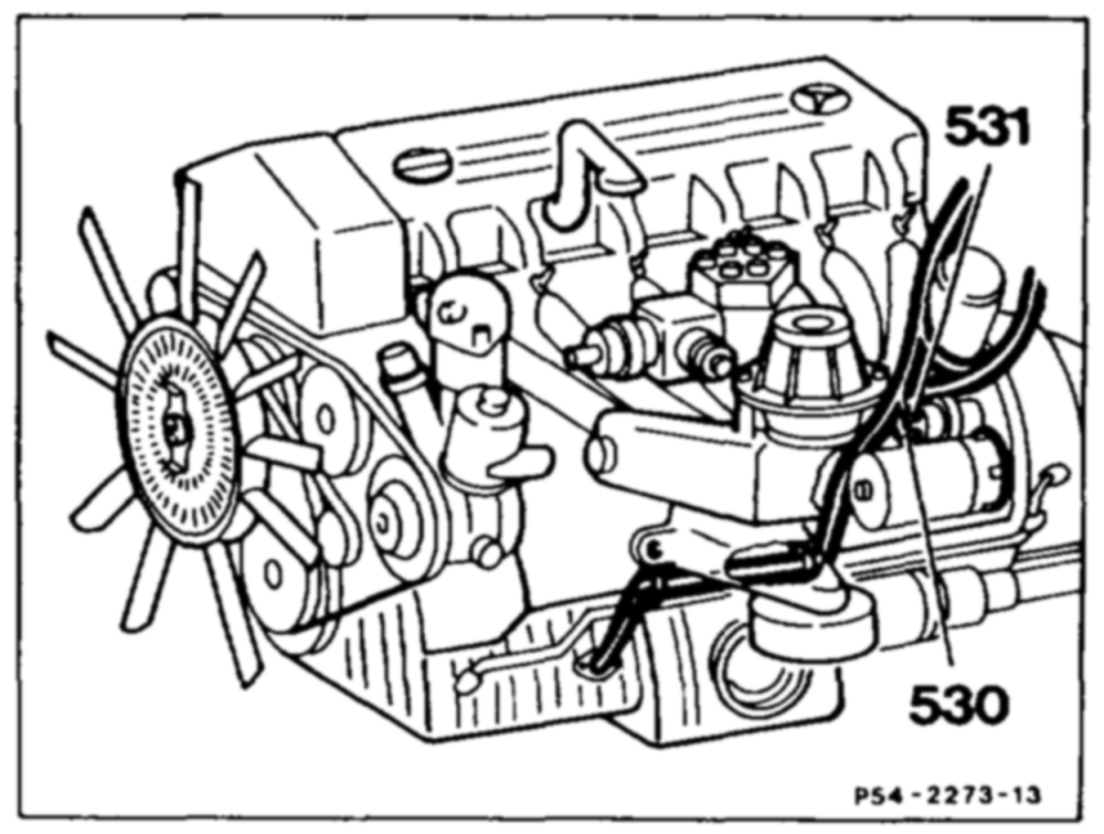
12 Unscrew electric cables. Turn nut (531) down. Unscrew cross-head screw (530). Detach cable from the oil level gauge and from oil pressure sensor.
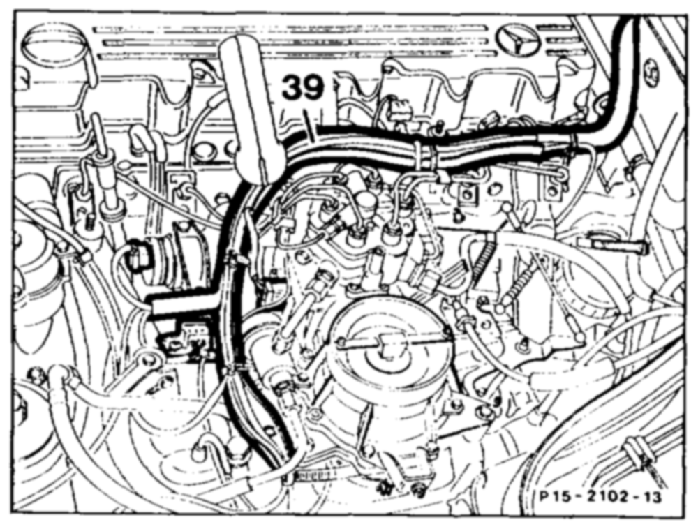
13 Slacken all cable straps of the engine wiring harness. Detach all plug connections along the engine wiring harness. Remove engine wiring harness (39).
14 Detach heating hoses and vacuum lines in engine compartment.
ie RA 01.1113-0300/8
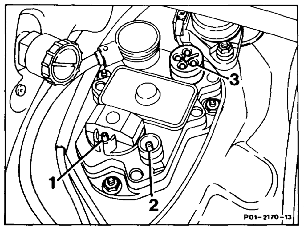
sensor and vacuum line at ignition contro} unit connector-sensor.
Vacuum connection – 2 Control line connection 3 Connector-sensor connection
16 Detach extraction line (arrow) of fuel evaporation contro! system from connector fitting on left wheelhouse.
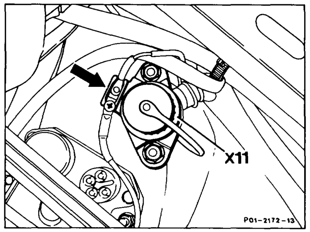
17 Detach terminal block terminal TD (arrow) next to diagnostic socket (X11), unscrew diagnostic socket, detach grey cable from TDC sensor on rear of diagnostic socket.
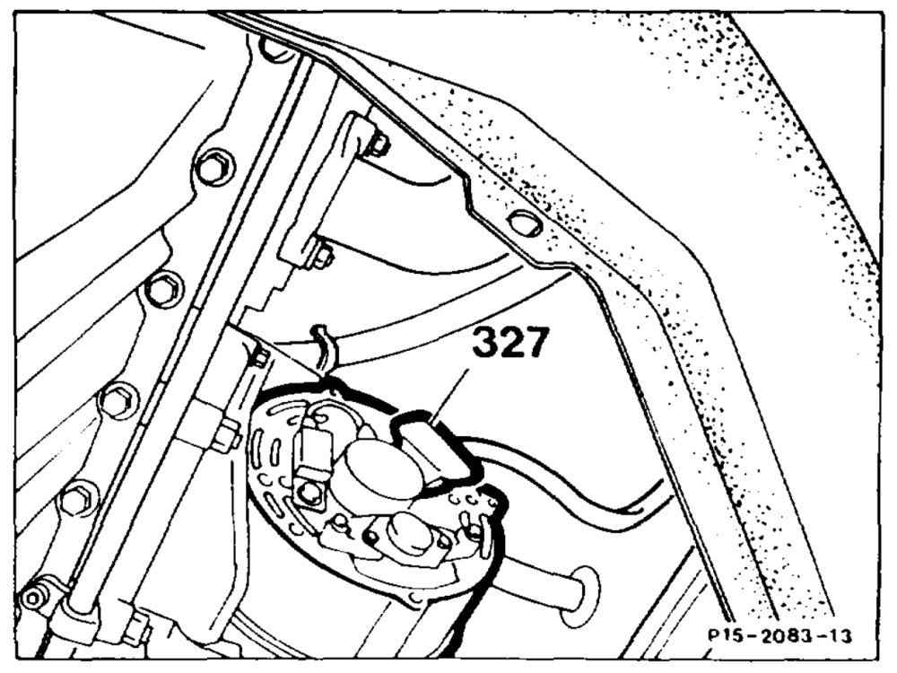
18 Detach connector (327) at alternator.
oie RA 01.1113-0300/9
component compartment wall.
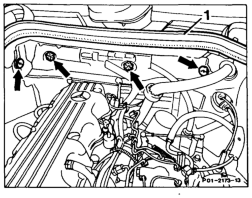
20 Remove covering of wiring harnesses by unscrewing four plastic screw connections (arrows).
21 If car fitted with self-levelling suspension, unscrew cabie bracket at front of engine.
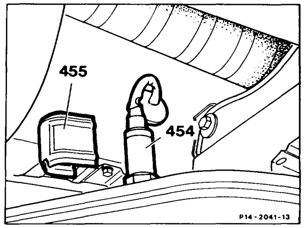
22 Remove guard plate (455), unscrew lambda sensor (454).
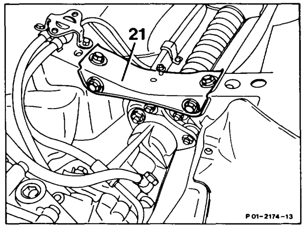
23 Remove exhaust system and shield above exhaust system (49-7000).
4MATIC
Remove shields on transfer case and centre tunnel.
24 Unscrew cross bar (524) on centre tunnel. Pay attention to tightening torque.
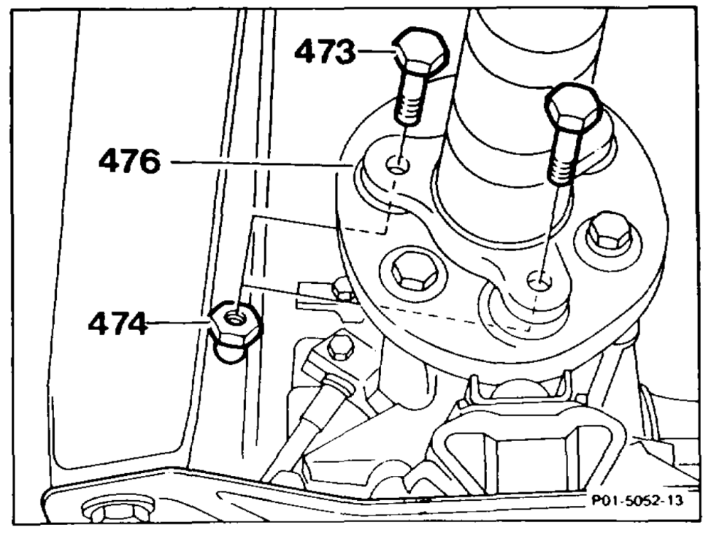
25 Remove propeller shaft. Unscrew nut (474), withdraw bolt (473). Pay attention to tightening torque. Flexible joint (476) remains on transmission.
a RA 01.1113-0300/10
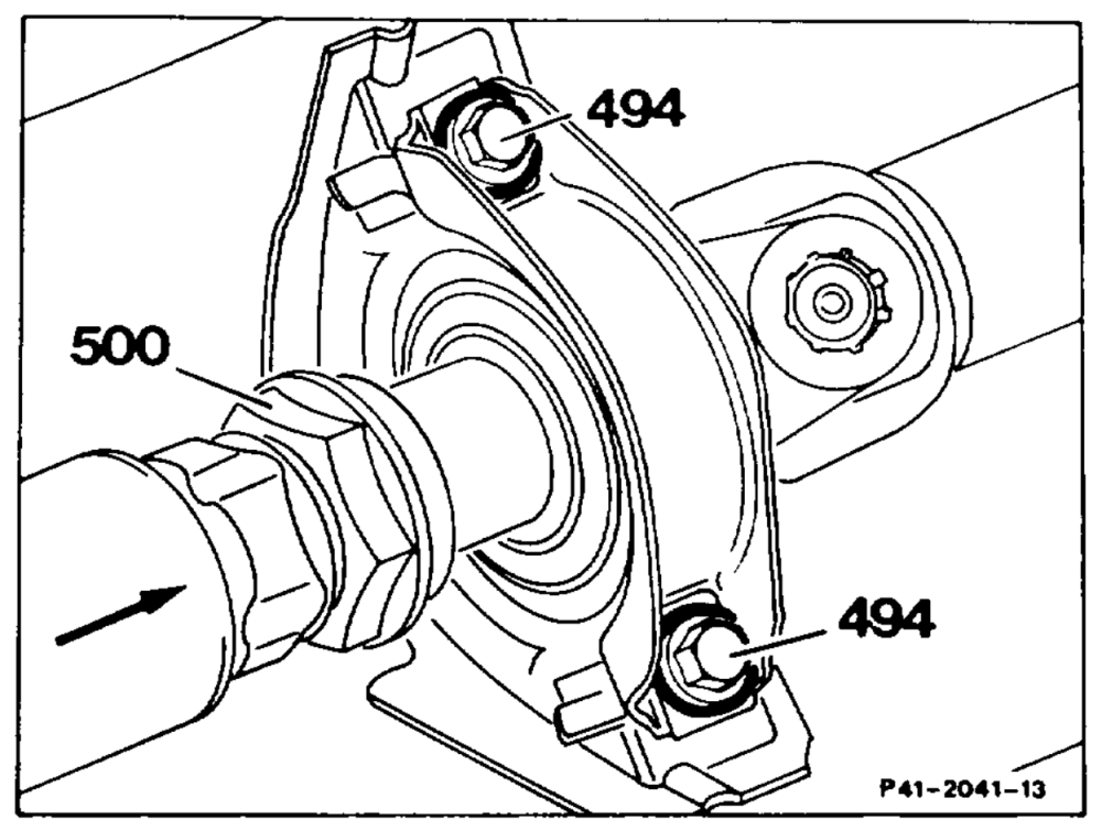
intermediate bearing, but do not remove. Pay attention to tightening torque.
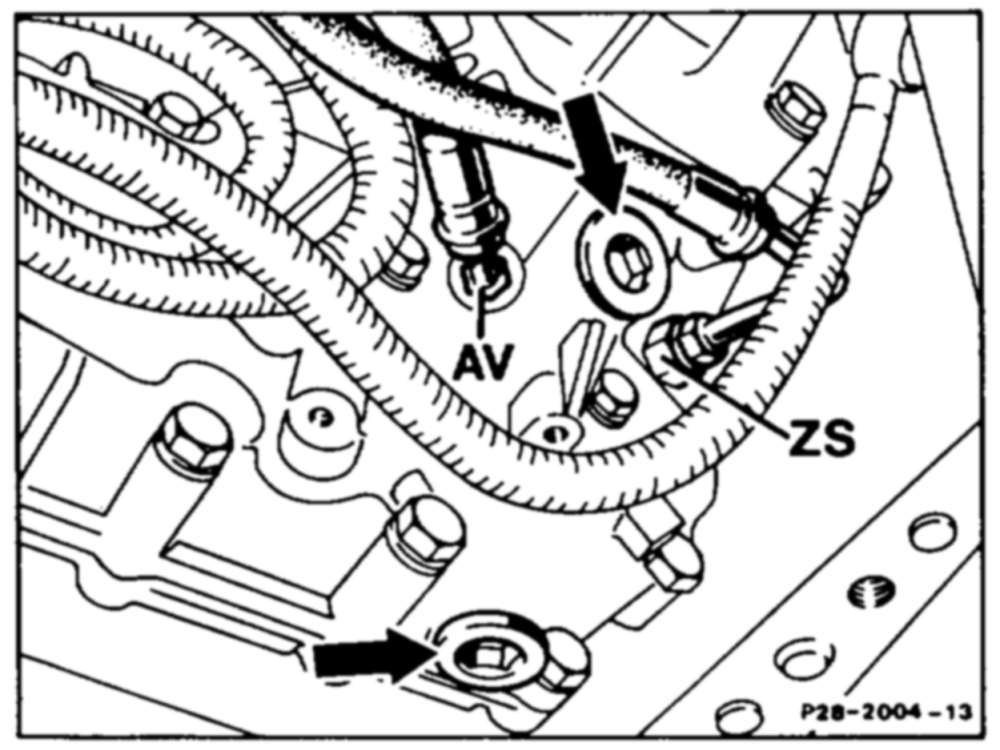
27 Slacken clamping nut (500) (waf 41/46) from propeller shaft. Push back propeller shaft in direction of arrow as far as possible. Pay attention to tightening torque. –
4MATIC
28 Unscrew hydraulic lines (AV, ZS) at transfer case.
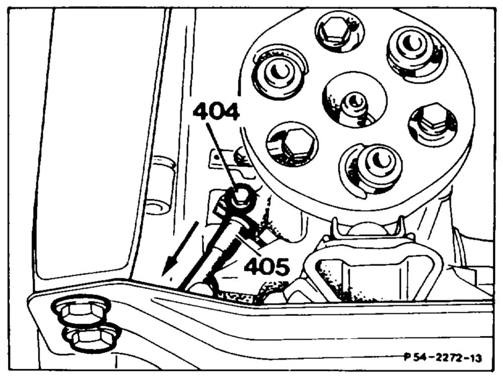
29 Unscrew bolt (404). Withdraw speedometer shaft (405) in direction of arrow.
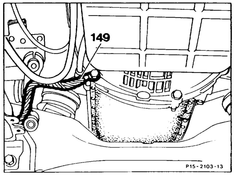
30 Unscrew ground cable (149) at transmission.
wp RA 01.1113-0300/11
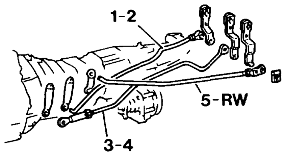
clip locks off the transmission shift levers and then take off shift rods.
P26-0010–13
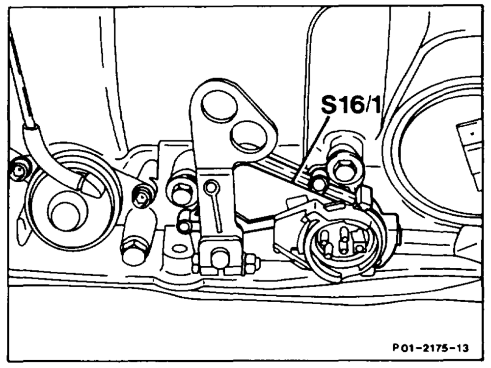
32 If automatic transmission fitted: detach shift rod at centre shift mechanism. Turn white plastic locking element on starter lockup, backup light switch (53) approx. 45° to the right and detach cable connector. Detach cable at kickdown solenoid valve.
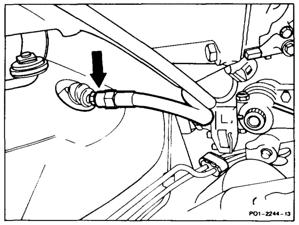
33 If manual transmission fitted: disconnect hydraulic line (arrow) to the slave cylinder at hose screw union. Seal lines with dummy plugs or extract fluid from the rear chamber of the combined reservoir.
4MATIC
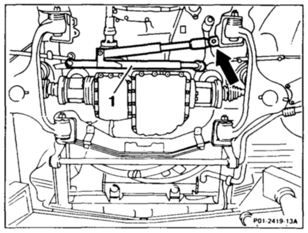
34 Remove drag link (1) together with steering damper. Unscrew steering damper (arrow) at the body. Remove drag link by using the tapered removing tool 201 589 08 33 00.
Note Renew self-locking nuts. Pay attention to tightening torques.
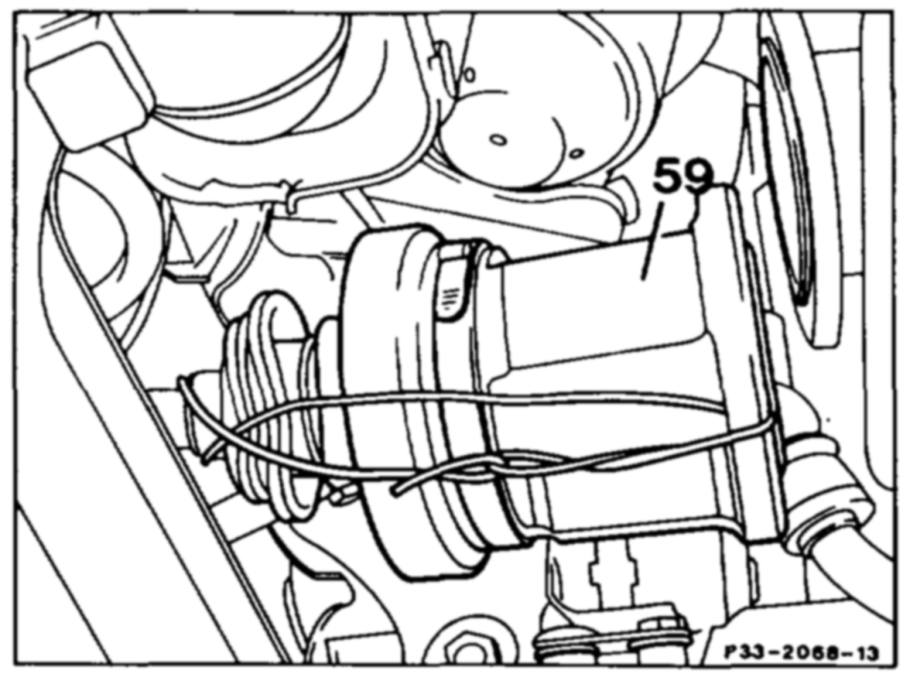
footbrake to slacken the six bolts (microencapsulated). Push front axle shafts together as far as possible and fix in this position with wire. Place front axle shaft on wishbone arm. Pay attention to tightening torque.
Note Do not pull inner joint too far apart and wrap to prevent the needle-bearing tripod joint rollers from dropping out of the journals at the tripod cross.
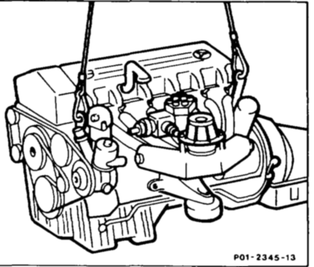
36 Attach engine hoist to the suspension lugs of the engine. Adjust engine hoist so that the engine can be raised horizontally.
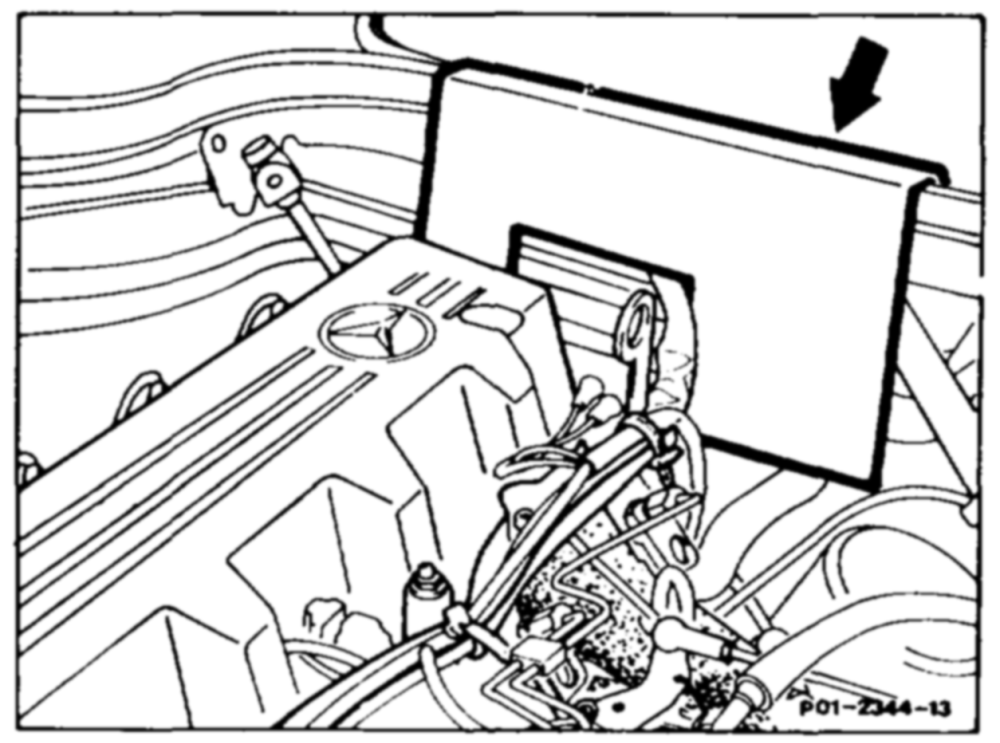
37 Insert guard plate (arrow) between component compartment wall and engine.
38 Support transmission with car jack or inspection pit lift.
ae RA 01.1113-0300/13
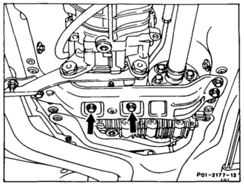
M8 20 Nm.
40 Remove rear engine support. Tightening torque M10 35 Nm.
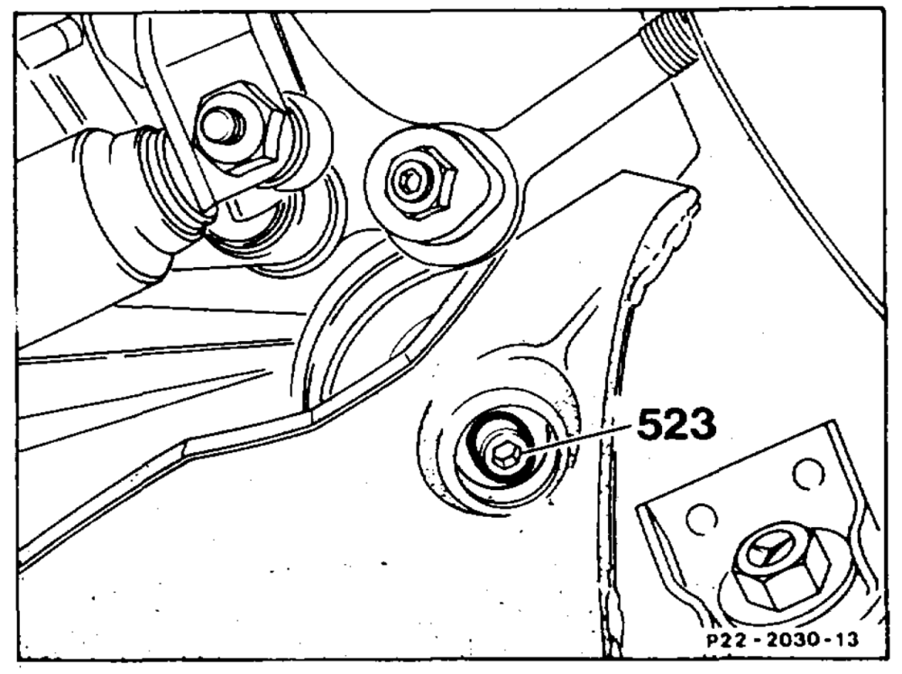
41 Unscrew bolt (523) on left and right front engine mount from below. Tightening torque
40 Nm.
4MATIC
2 bolts from below. Tightening torque 20 Nm.
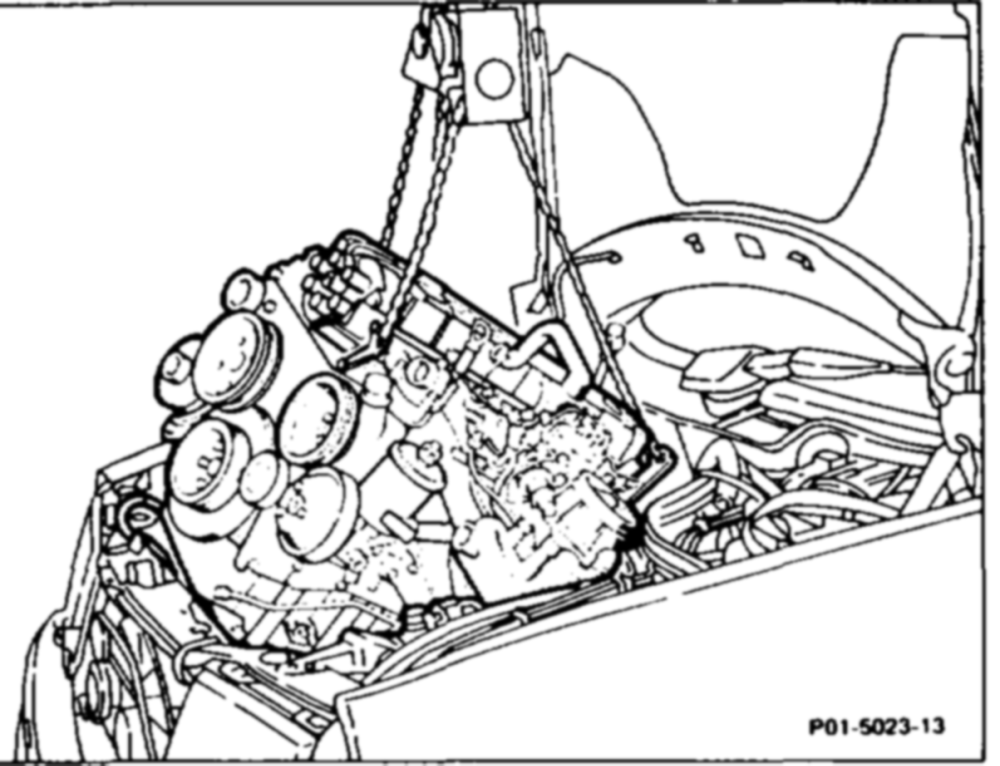
42 Move engine with transmission into inclined position and lift out of engine compartment by adjusting engine hoist several times, or install as appropriate.
Note When tilting engine, pay attention to rear suspension lug and to the oil filter.
am RA 01.1113-0300/14
4MATIC
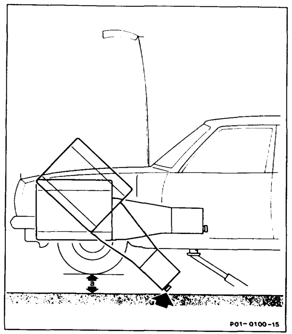
Do not place any load on, and do not strike lube oil line on transfer case (arrow) otherwise this may cause leaks.
a = approx. 30 cm Hook height at least approx. 260 cm.
Install in the reverse order.
43 Check front and rear engine mounts.
44 Check coolant, oil and fuel hoses.
45 If automatic transmission fitted: adjust cable for control pressure (27-100).
46 Check tightening torque of oil drain plugs.
47 Adjust engine oil in engine and transmission to correct level.
48 Pour in coolant, check anti-corrosion/ antifreeze agent, adjust to correct level (20-0100).
4MATIC
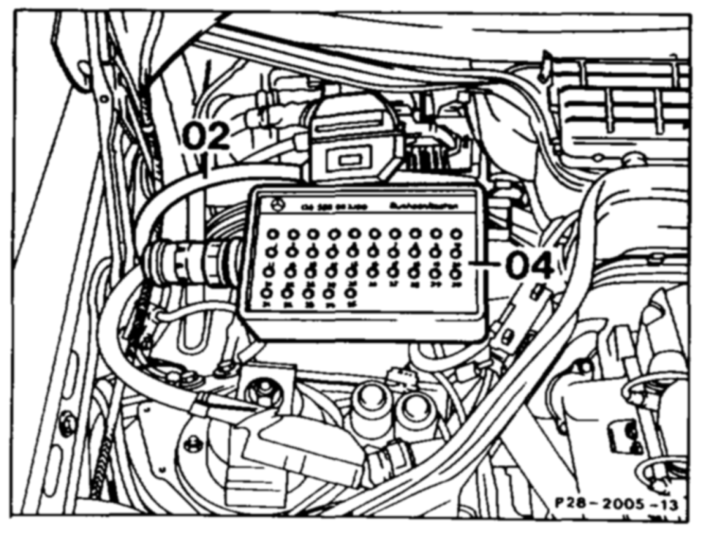
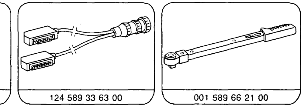
49 Bleed hydraulic system. Connect contact box 124 589 00 21 00. Disconnect 4MATIC control unit and connect 25-pin connector to the contact box (04) 124 589 00 21 00 with the Y cable (02). The contro} unit remains disconnected.
wine RA 01.1113-0300/15
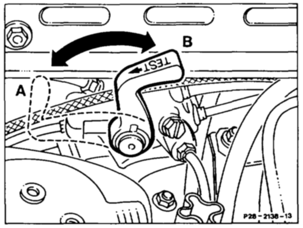
level in reservoir. Service valve in test position. To bleed, start engine and run for approx. 30 seconds at 1000 – 2000 rpm. After bleeding, move service valve back to operate position.
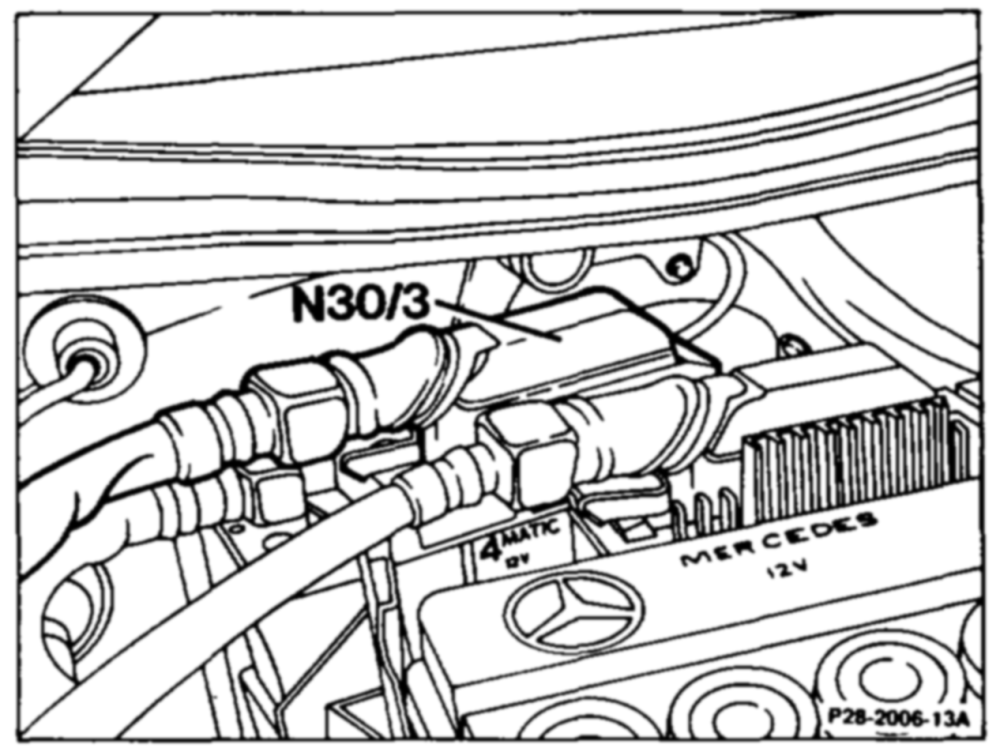
A Test positon B Operate position
4MATIC
51 Detach 25-pin connector from control unit (N 30/3) and connect contact box 124 589 00 21 00. Service valve in operate position. Apply parking brake. Start engine and run at idling speed.
4MATIC
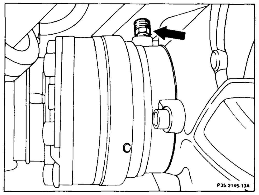
52 Bleed rear axle differential lock. Activate HS solenoid valve by jumpering contact 8 and contact 2 (ground) at contact box 124 589 00 21 00. Open bleeder (arrow) on rear axle centre section for as long as is necessary for the hydraulic oil to flow out free of bubbles (attach hose).
4MATIC
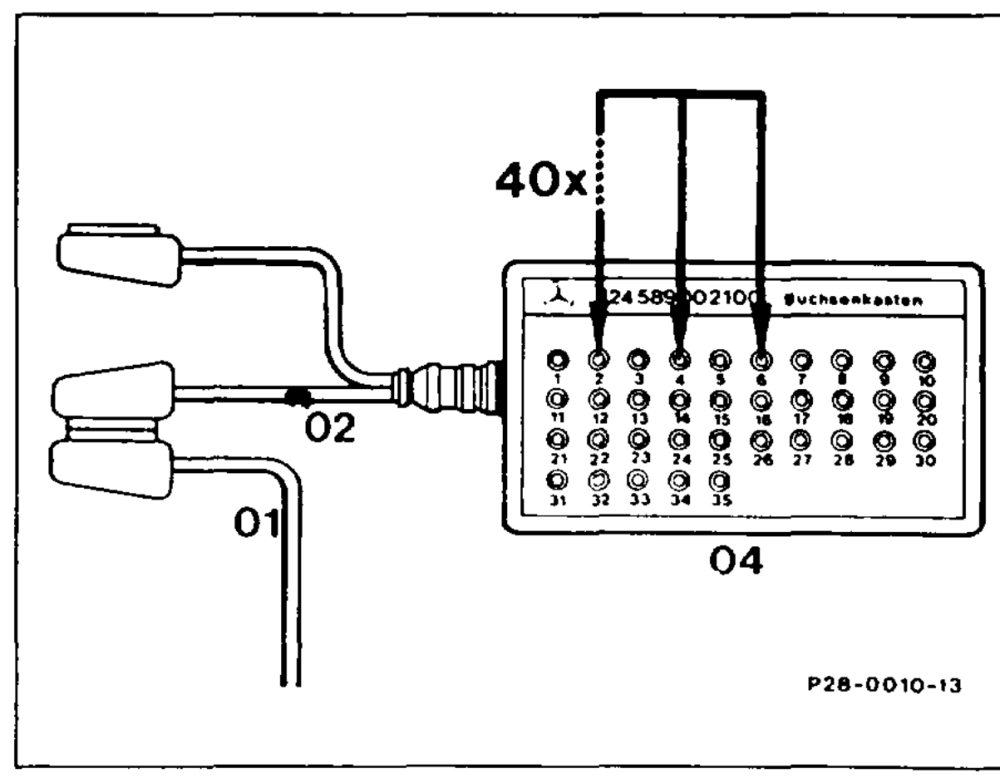
53 Bleed AV and ZS multi-disc clutches. Activate AV and ZS solenoid valve together 20 times by connecting contacts 4 and 6 at the contact box 124 589 00 21 00 and jumpering to contact 2 (ground) 20 times.
Note The trapped air is removed through the hydraulic oil by actuating the AV and ZS multi-disc clutches several times.
Note After completing the work, the faults stored in the fault memories must be processed (rectified cause) and erased.
See Diagnosis Manual Volume 2: Index 0: connecting and using testers
55 Check idle speed, adjust if necessary
56 Run engine and check for leaks.
oy RA 01.1113-0300/17
B. Model 107, 126, 129, 201
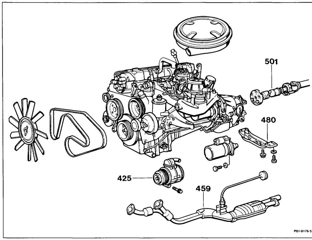
Preceding work: Operation no. of operation texts and work units or standard texts Hood on model 107 removed (88-300). and flat rates Bottom engine compartment panel removed (Maintenance 01-2400, 01-2800 Manual Volume 2, Op. no. 6190). Aw cleaner removed (09-1051). Radiator removed (20-4200). Viscous fan clutch removed (20-3120).
Ground cable at battery detach, attach. If air conditioning fitted attach guard plate to condensor, detach poly Vbelt (if AC fitted), attach (13-3420) (steps 2, 3). If air conditioning fitted ………..0…00.. detach refrigerant compressor (425) with pipe group connected, place to the side, attach (step 4).
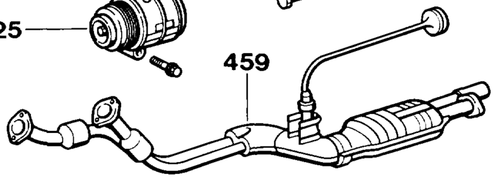
=. RA 01.1113-0300/18 extract oil from reservoir, adjust oil to correct Power steering pump level (46-7150) (step 6). Oit lines of power steering pump detach, attach. Renew seals (steps 5 and 7). Fuel lines ……….0.. 000 ..2..0.0200008detach and seal, briefly open fuel filler cap beforehand, attach (step 8). Bowden cable (accelerator control) Model 129, 201 detach, attach (30-3402) (step 9). Accelerator control linkage on Model 107, 126 … detach, attach (steps 10 – 11). Heating hoses and vacuum lines detach, attach (step 13). Engine wiring harness detach, attach (steps 12, 14). Ignition control unit and diagnostic socket (X11) . . detach wiring and connectors, plug in (steps 15, 20). Vacuum lines detach, fit on (steps 16 – 18). Starter on Model 129 remove, install (15-700) (place to side with wiring connected) (step 19). Alternator on Model 107, 126, 129 detach connector, attach (step 21). Alternator on Model 201 remove, install (step 22). Wiring harnesses remove covering, install (steps 23 — 25) Lambda sensor remove, install (step 26). Exhaust system (459) and shield above exhaust remove, install (49-7000) (step 27). system Propeller shaft (501) at flexible joint detach, attach. Renew self-locking nuts (step 28). Propeller shaft intermediate bearing slacken, tighten (step 29). Clamping nut slacken, push back and tighten (step 30). Transmission ………….002 002 cee eee unscrew electronic speedometer and ground cable, screw on (steps 31 — 32). Hydraulic lines for clutch on Model 129 unscrew, screw on (step 33). detach, attach (steps 34, 35). Starter lockout switch (automatic transmission) turn locking element, detach connector and fit on (step 35). Transverse yoke centre section of Model 126 unscrew, screw on. Renew self-locking bolts (step 36). Drag link and steering damper on Model 107, 126, 201 unscrew, screw on (46-550) (step 37).
we RA 01.1113-0300/19
Rear engine support (480) without engine mount remove, install (22-2120). Engine shock absorber on model 107, 126 remove, install. unbolt, bolt on from below (22-2110) Front engine mounts, left and right Guard plate at component compartment wall insert, remove (step 43). Engine with engine hoist lift out (steps 38, 44). Seal at heater feedpipe (engine suspension eye) replace (25 Nm). Front engine mounts ………..-…..0.0– check. Coolant, oil and fuel hoses ………….-.-.- check. If automatic transmission fitted adjust Bowden cable for control pressure (27-100). Idling speed check and adjust. Oil drain plugs check tightening torque. Oil level in engine and transmission check (18-0020). Coolant pour in, check anti-corrosion/antifreeze agent (20-0100). read, erase.
Note After completing the work, faults stored in the fault memories must be processed (rectified cause) and erase.
See Diagnosis Manual Volume 2: Index 0: connecting and using testers. Model 129 with ADS: steering angle sensor initialize, see Diagnosis Manual Chassis Volume 2
run and check for leaks.
aie RA 01.1113-0300/20
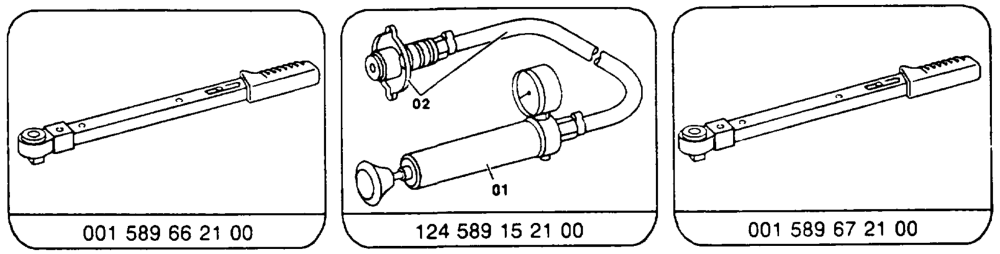
Special tools
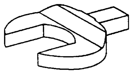
pe 000 589 40 37 00 S NG 126 589 00 01 00 S – 112 589 00 72 00
Commercially available tools and testers
Designation eg. make, order no. Engine hoist No. 3188 eg. Wilhelm Backer self-locking Herder Str. 13 D-42853 Remscheid
Anti-corrosion/antifreeze tester eg. Philipp Gather Preston-VU-Check D-40822 Mettmann 2
Shop-made tools
Guard plate for radiator/condensor Dim. approx. 480 x 680 x 1
Metal panel for component compartment wall Dim. approx. 320 x 380 x 1
op RA 01.1113-0300/21
Note Remove and install engine with transmission.
AN In the case of engine damage affecting the pistons, valves etc., parts may get in up to just before the catalytic converter or pre-catalytic converter. When exchanging the engine, it is essential to remove these parts otherwise they may be pulsed back into the cylinders as a result of gas vibrations in the exhaust system and again cause engine damage. In addition, these parts may cause mechanical damage to the catalytic converter. In dealing with such engine damage, it is therefore essential to remove these foreign bodies in the exhaust system. Damaged catalytic converters must be replaced.
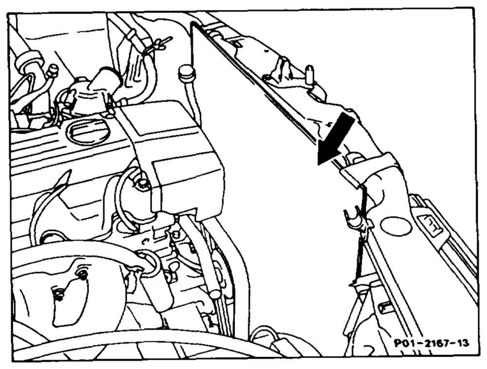
1 Detach ground cable at battery.
2 If air conditioning fitted: attach guard plate to condensor of air conditioning system (arrow).
3 If air conditioning fitted: remove poly-V-belt (13-3420).
mine RA 01.1113-0300/22
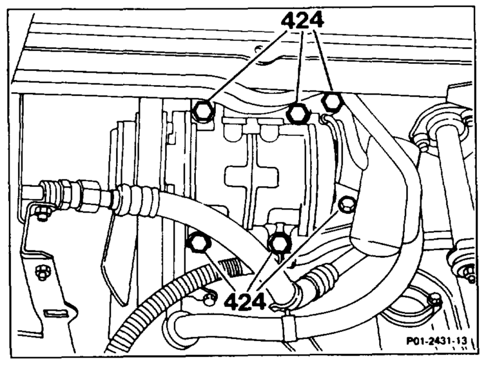
4 Detach refrigerant compressor of air conditioning system from crankcase. Unscrew bolts (424). Attach refrigerant compressor with pipe group connected to the side at the bottom of engine compartment. Unscrew hydraulic oil line at power steering pump and line bracket at front’on cross member.
Installation instruction
Pay attention to tightening torque.
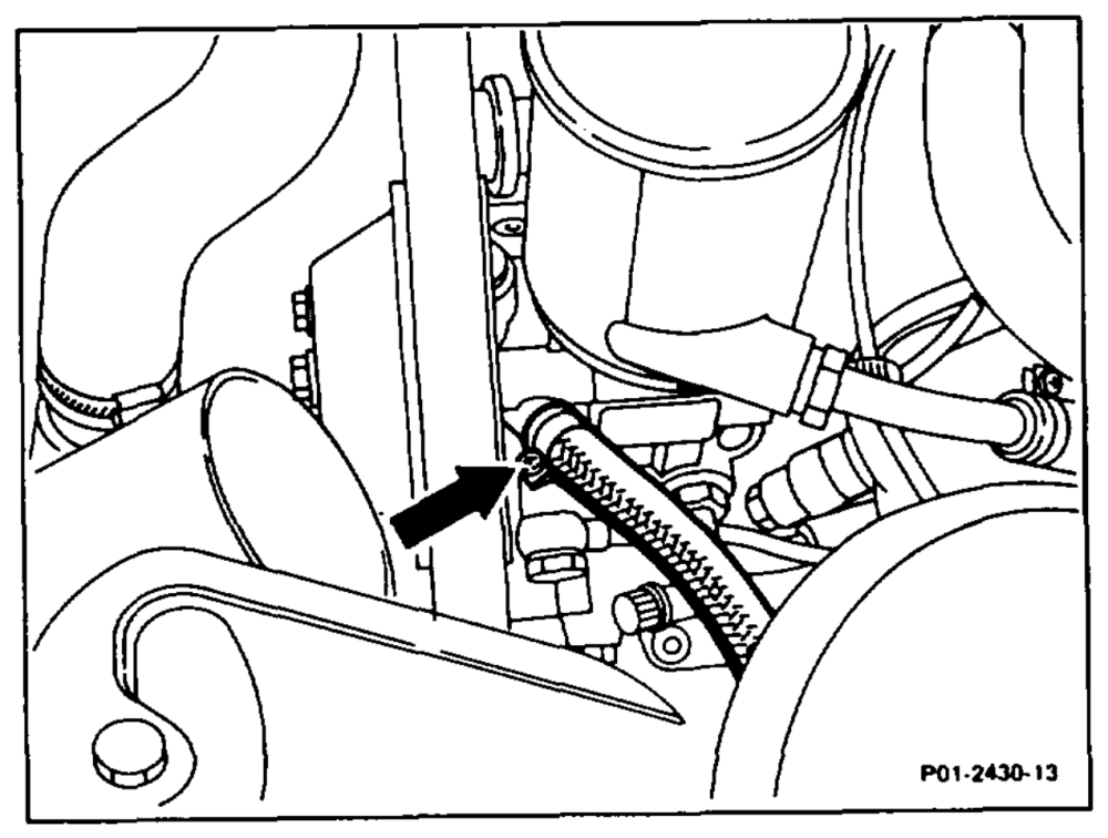
5 Slacken clip (arrow) and detach inlet hose of reservoir of self-levelling suspension at power steering pump and seal.
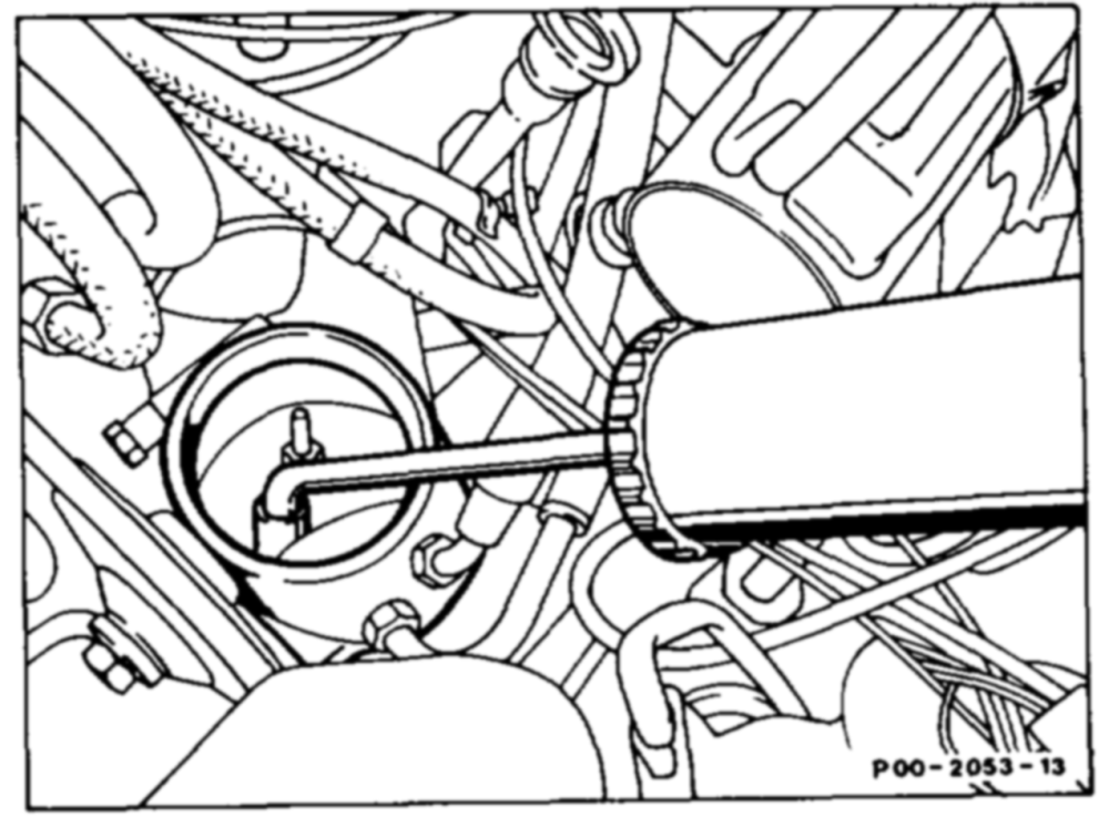
6 Extract oil from the reservoir of the power steering pump.
Installation instruction Check oil level of power steering (46-7150).
ci RA 01.1113-0300/23
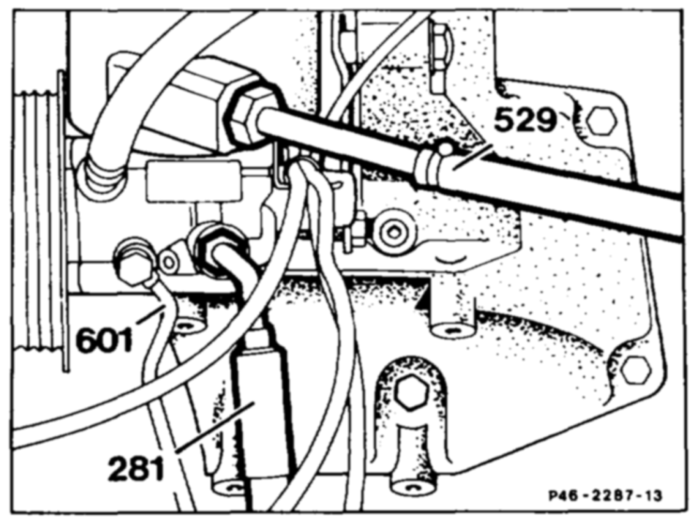
7 Unscrew high-pressure expansion hose (281), return line (529) to the steering gear and oil line (601) of the self-levelling suspension at the power steering pump.
Installation instruction Renew seals. ‘Pay attention to tightening torque of highpressure expansion hose (281) and return line (529).
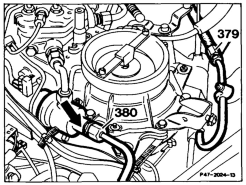
8 Briefly open the fuel filler cap to release the pressure in fuel tank. Unscrew fuel lines (379, 380). Hold the connection fitting (arrow) when slackening the fuel line (380).
Shown on model 124
Model 129, 201
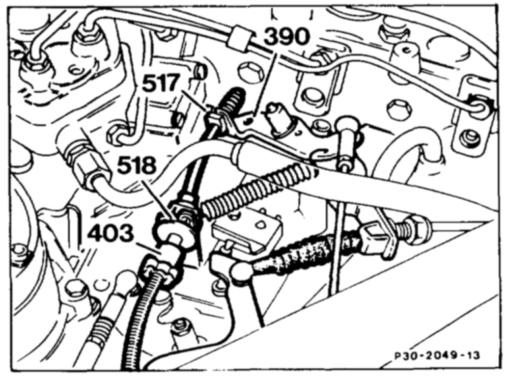
9 Detach Bowden cable of accelerator control. Press plastic guide (517) out of its seat in the fulcrum fever (390) and withdraw Bowden cable (403) through the siot in the fulcrum lever. Compress links of the plastic clip (518) and push clip with the Bowden cable (403) to the rear through the bracket.
Installation instruction
Adjust Bowden cable (30-3402).
one RA 01.1113-0300/24
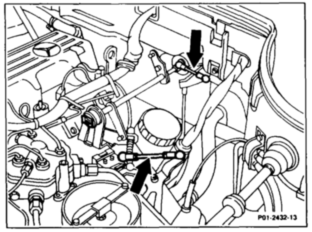
(arrows), turn to the left and tie tight.
Shown on model 126
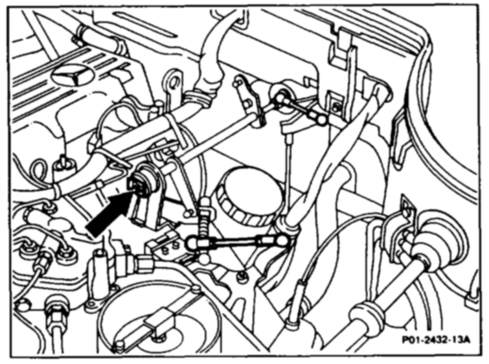
11 Take off clip at accelerator control linkage shaft (arrow) and withdraw the control linkage shaft from the mounting point and take out to the front.
Shown on model 126
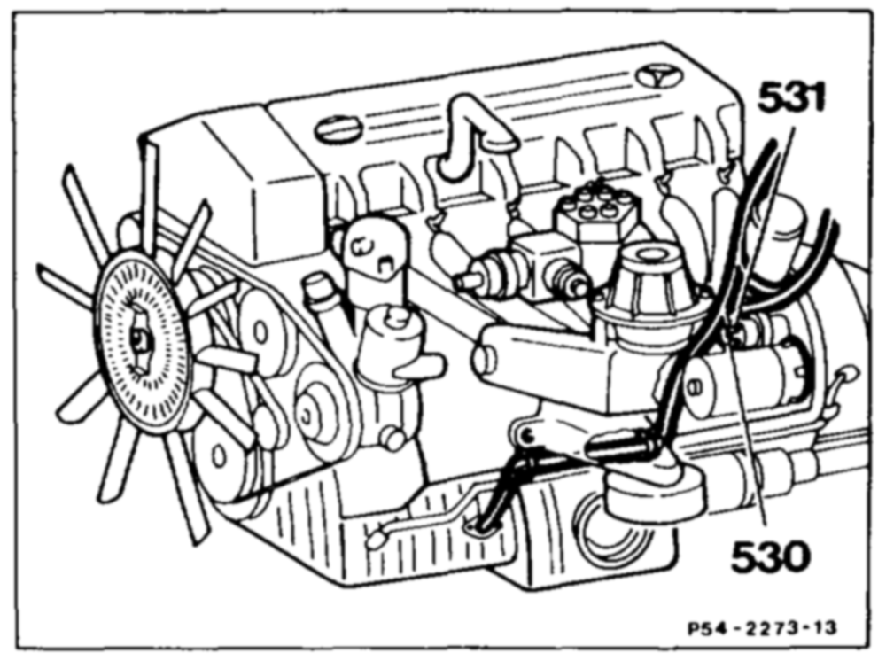
12 Unscrew electric lead. Turn down nut (531). Unscrew cross-head screw (530). Detach cable from oil level gauge and from the oil pressure sensor. Detach wiring harness from the rear suspension lug and withdraw upward.
13 Detach heating hoses and vacuum lines in the engine compartment.
oa RA 01.1113-0300/25
wiring harness. Detach all the plug connections along the engine wiring harness. Remove wiring harness.
15 Detach control line from position sensor and vacuum line at the connector-sensor ignition control unit (arrow).
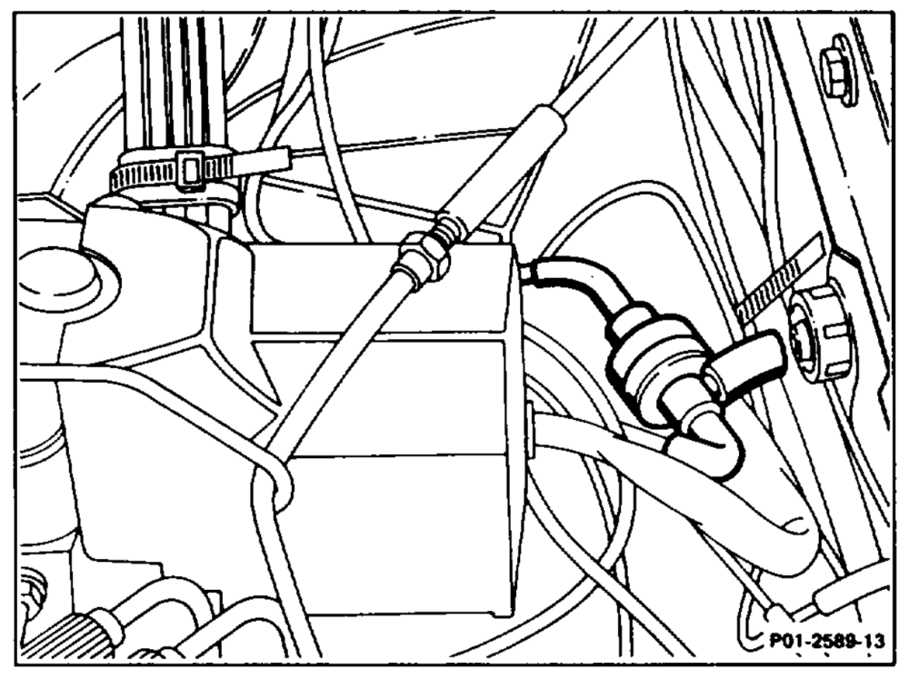
16 Detach vacuum lines.
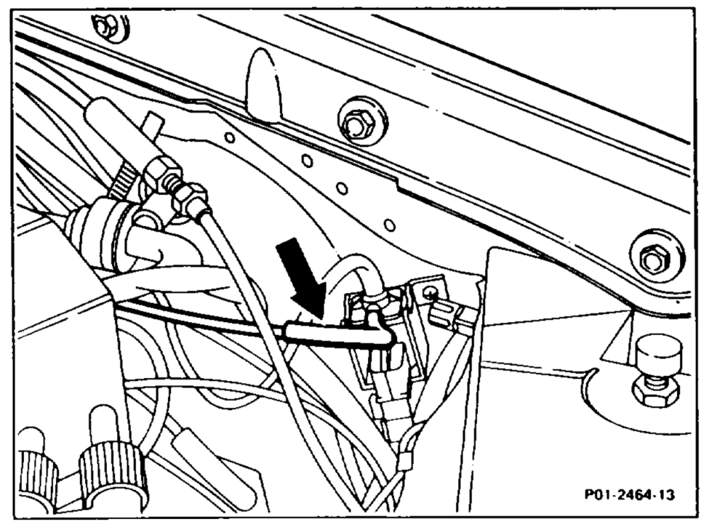
17 Detach extraction line of fuel evaporation control system from connection fitting on the left wheelhouse.
18 Detach control pressure line (arrow) at the left wheelhouse and place over the engine.
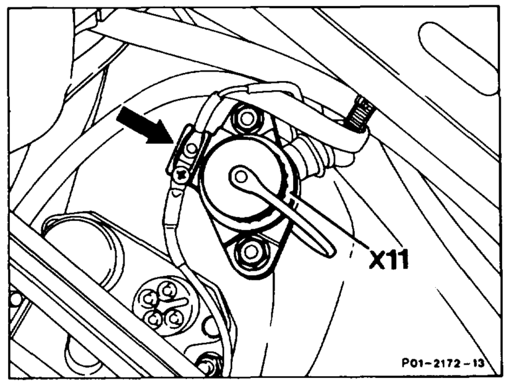
(15-700). Electric cables remain connected.
20 Detach terminal block terminal TD next to diagnostic socket (X11) (arrow), unscrew diagnostic socket, detach cable from TDC sensor on the rear of the diagnostic socket.
Model 107, 126, 129
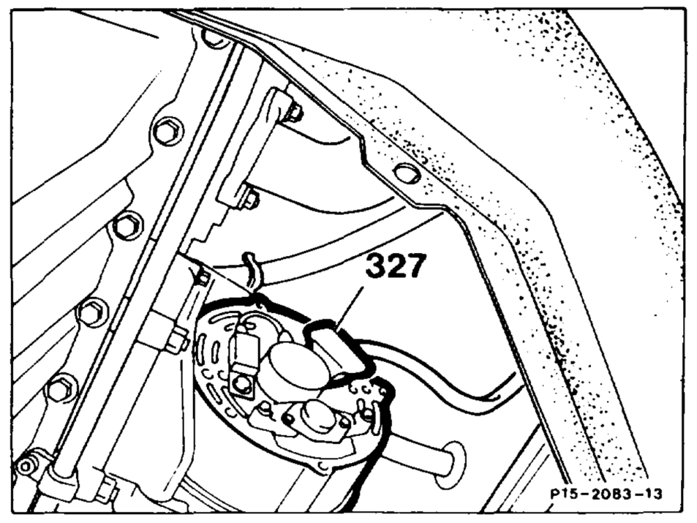
21 Unplug connector (327) at the alternator.
Model 201
22 Unscrew alternator and take out oil line of self-levelling suspension.
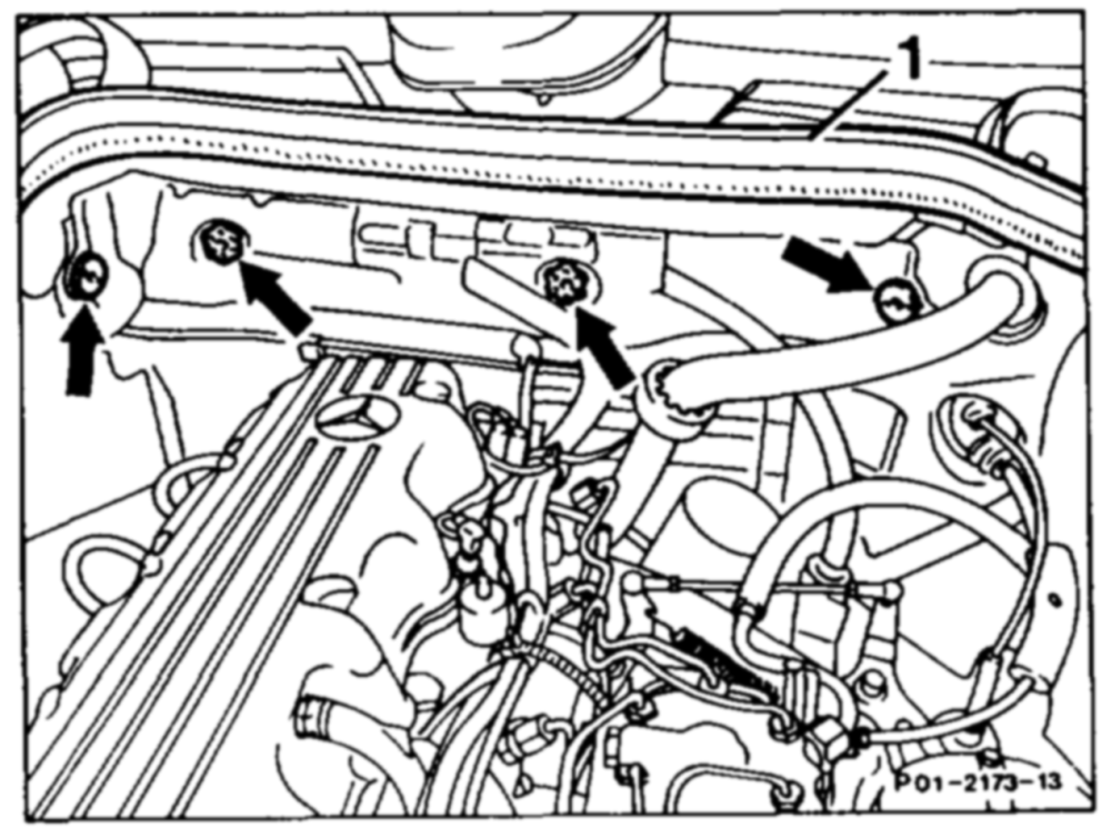
23 Remove rubber sealing strip (1) from the component compartment wall.
Model 129, 201
24 Remove covering of wiring harnesses by unscrewing four plastic screw fittings (arrows).
a RA 01.1113-0300/27
Model 126
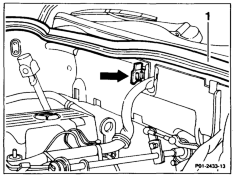
Remove rubber sealing strip (1) from the component compartment wall and open the fixture (arrow) of the engine wiring harness, take out wiring harness upward and place to the side.
Model 129
25 If car fitted with air conditioning, unscrew cable holder at front on engine.
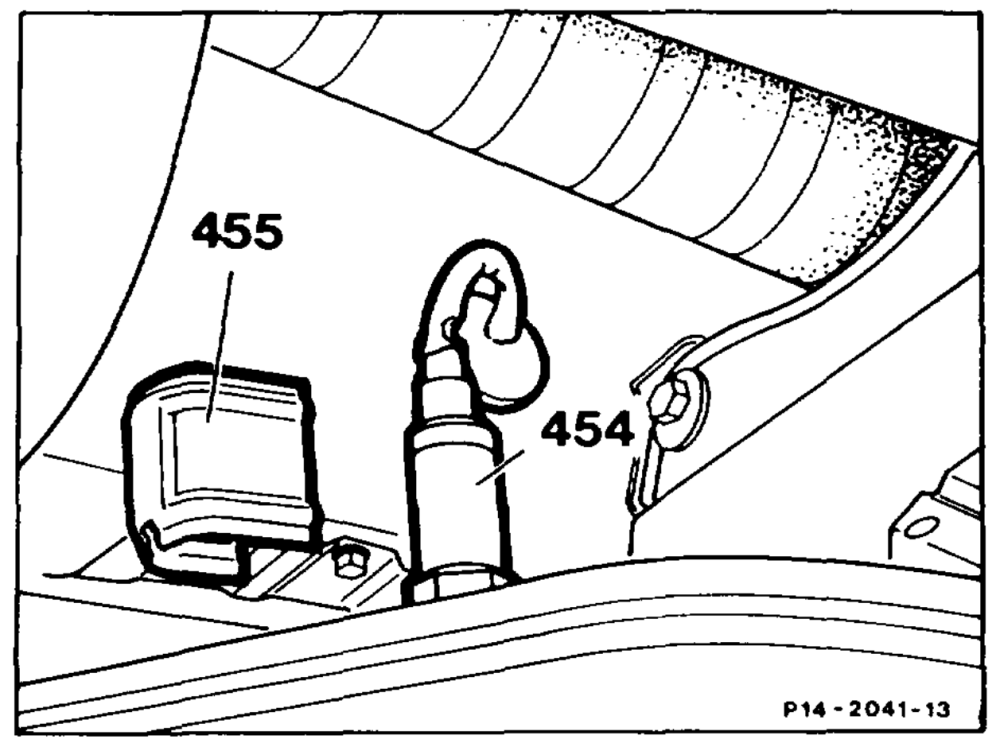
26 Pull off protective plate (455) and unscrew the lambda sensor (454).
27 Remove exhaust system and shield above exhaust system (49-7000).
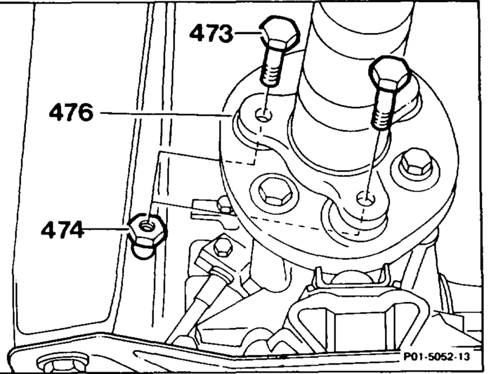
28 Detach propeller shaft. Unscrew nut (474), remove bolt (473). Flexible coupling (476) remains on transmission.
Installation instruction
Renew self-locking nuts. Tightening torque 45 Nm.
mis RA 01.1113-0300/28
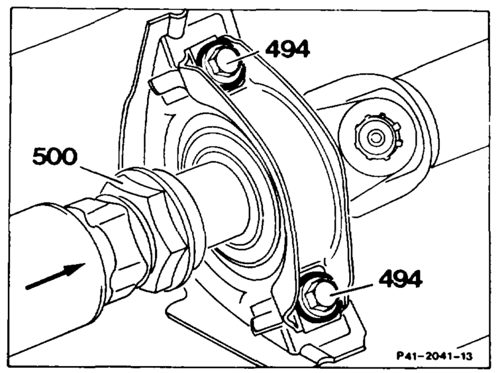
intermediate bearing, but do not remove.
Installation instruction
Pay attention to tightening torque.
30 Slacken clamping nut (500) (waf 41/46) from the propeller shaft. Push back propeller shaft in direction of arrow as far as possible.
Installation instruction
Pay attention to tightening torque.
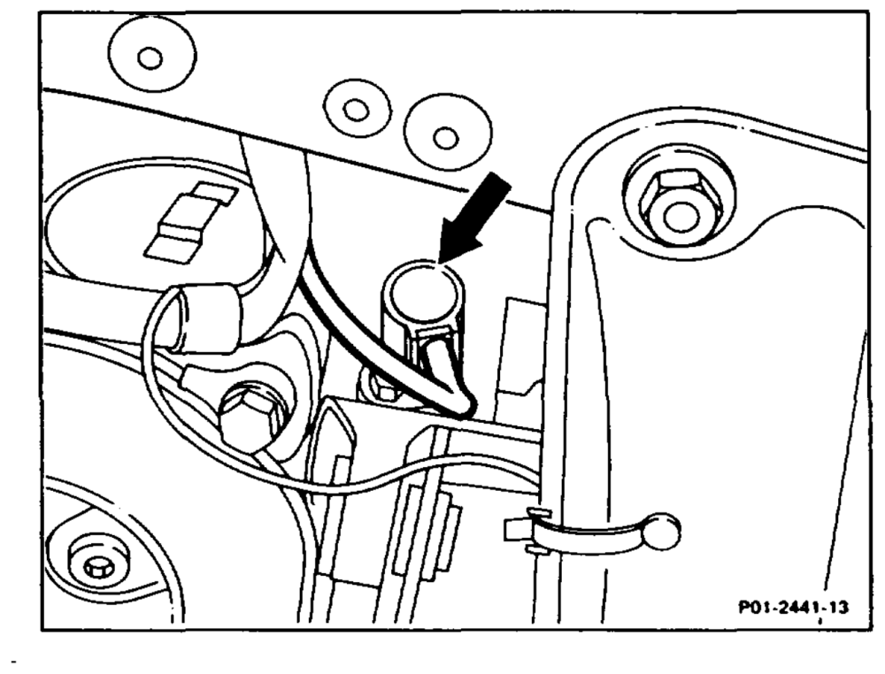
31 Unscrew cable for electronic speedometer (arrow) from transmission.
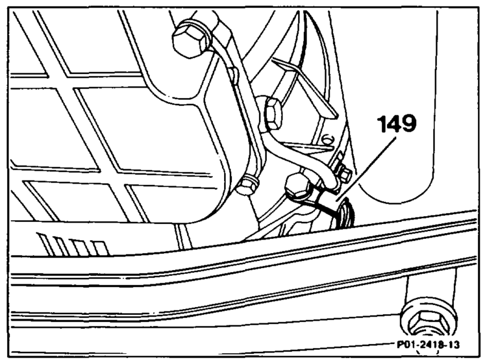
32 Unscrew ground cable (149) at transmission.
ie RA 01.1113-0300/29
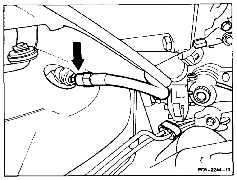
hydraulic line (arrow) to the slave cylinder at the hose union. Seal lines with dummy plugs or extract fluid from the rear chamber of the combined reservoir.
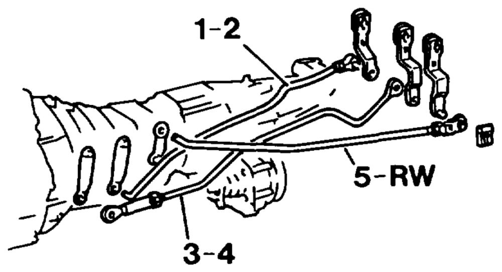
34 If manual transmission fitted: press clip locking elements off the transmission shift levers and then detach shift rods.
P26-0010–13
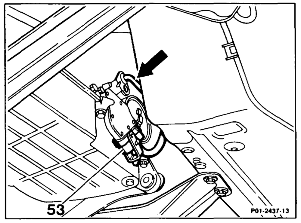
35 If automatic transmission fitted: detach shift rod (arrow) at the centre shift mechanism. Turn white plastic locking element on starter lockout, backup light switch (53) approx. 45° to the right and detach the cable connector. Detach cable on the kickdown solenoid valve.
Model 126
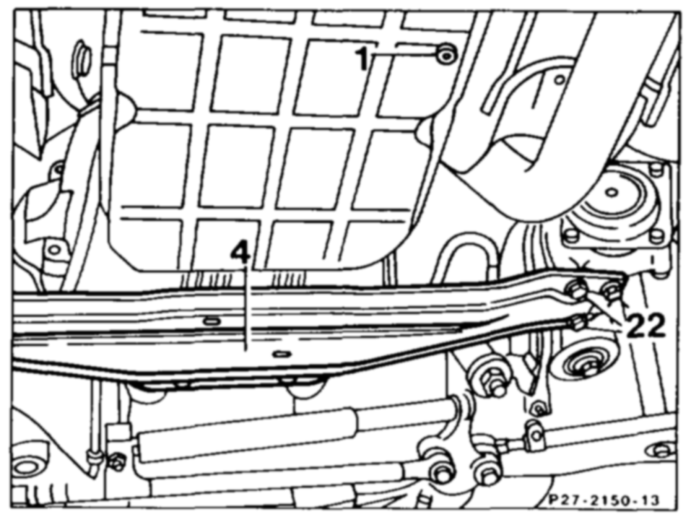
36 Unscrew cross yoke centre piece (4) on the front axle.
Installation instruction
Renew self-locking bolts (22). Pay attention to tightening torque.
a RA 01.1113-0300/30 damper on right, detach and turn drag link to the rear right (46-550).
38 Attach engine hoist to the suspension lugs of the engine. Adjust engine hoist so that the engine can be raised horizontally.
39 Support transmission with car jack or inspection pit lift.
40 Remove rear engine mount cross bar (22-2120).
Model 107, 126
41 Remove left and right engine shock absorbers.
42 Unscrew bolt at left and right front engine mount from below (22-2110).
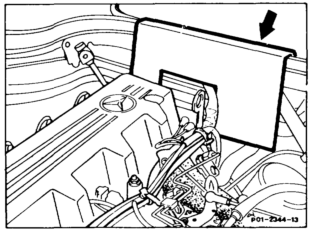
43 Insert guard plate (arrow) between component compartment wall and engine.
am RA 01.1113-0300/31
the engine compartment, or install as appropriate, by repositioning engine hoist several times.
Note When engine tilted, pay attention to the rear suspension lug and to the oil filter.
45 Check front and rear engine mounts.
46 Check coolant, oil and fuel hoses.
47 Install in the reverse order
48 lf automatic transmission fitted, adjust Bowden cable for control pressure (27-1000).
49 Check idling speed, adjust. Read fault memories, erase.
Note After completing the work, faults stored in the fault memories must be processed (rectified cause) and erase.
See Diagnosis Manual Volume 2: Index 0: connecting and using testers.
50 Check tightening torque of oil drain plugs.
51 Check oil level in engine and transmission.
52 Pour in coolant, check anticorrosionantifreeze agent (20-0100).
53 Run engine and check for leaks.
ane RA 01.1113-0300/32