Function description of crankcase ventilation
WIS 01-0400
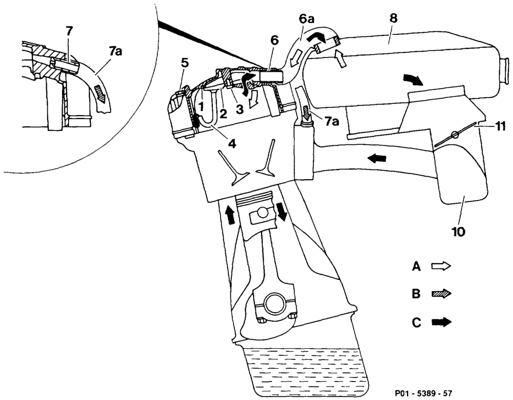
Vent hose to intake manifold Profile seal NOOSA WN — Air cleaner Oil separating plate Intake manifold M5 x8 cross-head screw Throttle valve Oil drain pipe Fresh au M5 x75 screw Pant load blow-by gases Air cleaner hose connection Full load blow-by gases Air admission or vent hose Hose connection (bypass hole 2 mm dia.)
RA 01.1112-0400/1
Function description
The engine blow-by gases flow out of the crankcase through the oil separator (2) in the cylinder head cover. The oil separated out at that point flows along a drain pipe (4) to the cylinder head. The blow-by gases pass to the combustion chambers in the following manner depending on the load state of the engine (intake manifold vacuum).
Part load ventilation
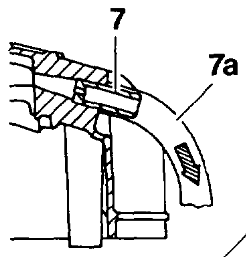
Throttle valve (11) closed or slightly open: The blow-by gases in part load are drawn off through the 2 mm dia. bypass hole in the hose connection (7) of the cylinder head cover along the vent hose (7a) into the intake manifold (10). The vacuum which is produced in the crankcase as a result draws in fresh air from the air cleaner (8) along the air admission or vent hose (6a).
Full toad ventilation
Throttle valve (11) open: At full load all the blow-by gases are led through the oil separator (2) in the cylinder head cover and along the air admission or vent hose (6a) into the air cleaner (8) where they are mixed with intake air and drawn off through the throttle valve into the combustion chambers.
RA 01.1112-0400/2