Coolant circuit
WIS 20-0050
Diagram
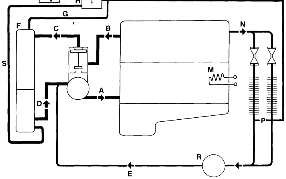
P20-5214–57
A From coolant pump to crankcase K Drain hose B From cylinder head to thermostat L Overflow tank (except models 107, 126) Cc From thermostat to radiator M Coolant preheater D From radiator to coolant pump N From cylinder head to heat exchanger E From circulation pump to coolant pump P Heat exchanger F Radiator R Electric circulation pump G Vent hose $s Coolant filling hose Expansion tank with coolant level indicator Vent line from heat exchanger (P) to expansion H T Pressure cap tank (H). Installed in model 129 as of 11/1990 as J of vehicle ident end no. 022 921.
«mide RA 20.1112-0050/1
A Coolant pump „bypass mode”:
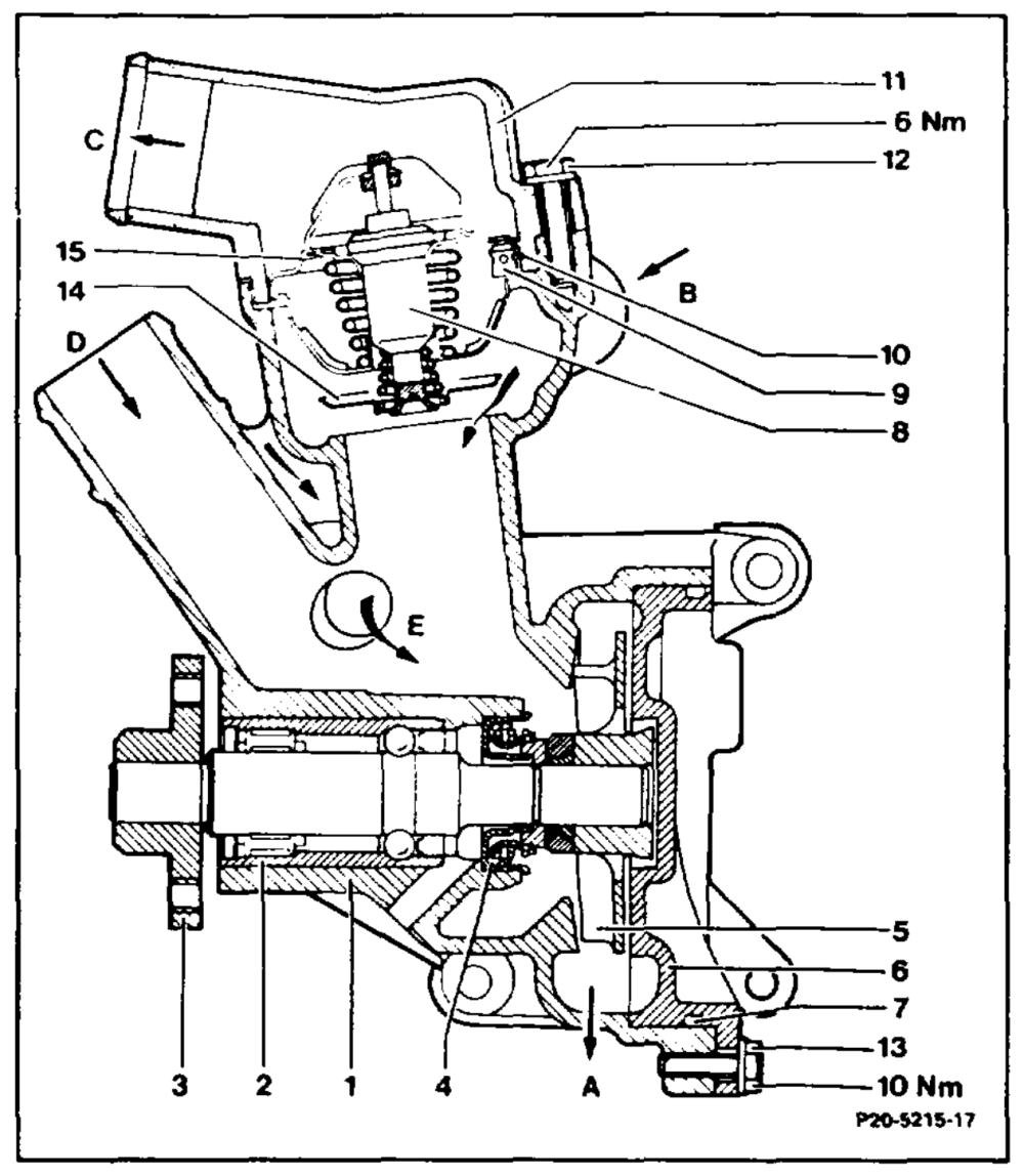
Main valve (15) closed. The coolant circulate from the cylinder head through the coolant pump to the crankcase.
WOOBNANHFWN=]|-MOODDYD To crankcase From cylinder head To top af radiator From bottom of radiator From heater Pump housing Pump shaft Flange Cassette-type seal Impeller Spiral housing O-ring Thermostat Ball valve 10 O-ring 11. Cover 12 Bolt + washer 13. Bolt + washer 14 Bypass valve 15 Main valve
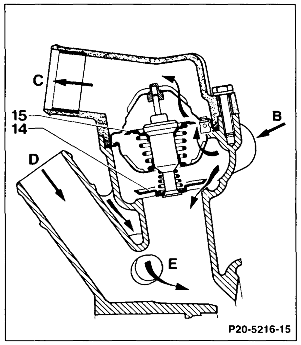
B Coolant pump „mixed mode”:
The main valve (15) is partially open. Coolant circulates partially through the radiator to the crankcase.
es2mMOOd From cylinder head To top of radiator From bottom of radiator From heater Bypass valve ae Main valve
«mme §=RA 20.1112-0050/2
C Coolant pump „cooling mode”:
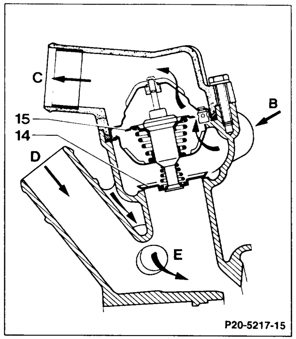
Main valve (15) fully open, bypass valve (14) closed. The coolant flows from the cylinder head through the radiator to the crankcase.
B From cylinder head C Ta top of radiator D From bottom of radiator E From heater 14 Bypass valve 15 Mann valve
«mine = RA 20 1112-0050/3