Testing electronic ignition system with variable characteristics EZL
WIS 15-1250
Operation no. of operation texts and work units or standard texts and flat rates: 15-1250.
P16-5067–57
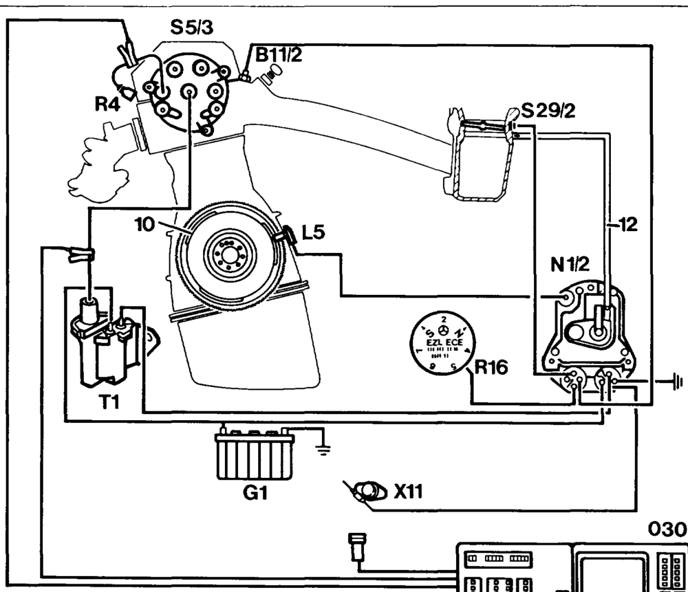
Connection diagram for engine tester with oscilloscope
Throttle vatve switch, full load/idle speed $29/2 Coolant temperature sensor (EZL/KE, LH), 4-pin B11v/2 recognition G1 Battery Ignition coil 11 Crankshaft position sensor L5 Diagnostic socketvterminal block, terminal TD X11 N1/2 EZL ignition control unit Segments on flywheel/driven plate 10 R4 Spark plugs Vaccum line EZL resistance trimming plug 12 R16 Engine tester with oscilloscope 030 $5/3 High voltage distributor
wie §=RA 15.1132-1250/1
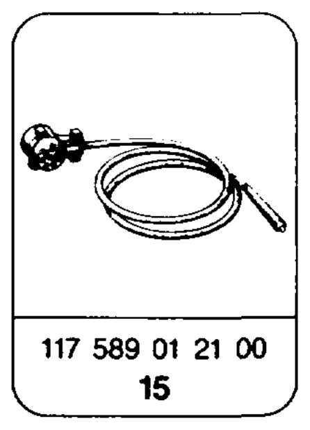
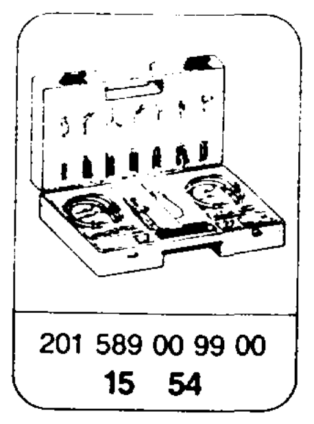
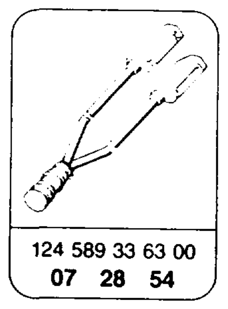
Special tools
Commercially available tools and testers
Designation e.g. Make, order no.
Sun, DMM-5 Multimeter Fluke, Multimeter 23 Hermann, Avometer 2003
Engine tester Hermann, Datascope 9800 Bosch, MOT 301/400 Sun, 2110 BEAR, D ACE
A Pay attention to the safety regulations when working on the ignition system (15-0505). Switch off ignition when plugging in and unplugging the connectors at the EZL ignition control unit.
Note If dealing with faults regarding handling, first of all test the ignition. Then, continue fault finding at the KE injection system.
The test is divided into two sections:
b) Engine running
a) Engine not running
Faults in the ignition timing or at the In this section the basic functions of the ignition corresponding components can affect vehicle system are tested. If the fault cannot be rectified, continue troublehandling. shooting in section b), „Engine running.”
whip §=RA 15.1132-1250/2
Test data
Resistances (test data from 0 – 100 °C)
| Ignition coil | primary (terminals 1 and 15) | Q | 0.3–0.6 | |
| Ignition coil | secondary (terminals 1 and 4) | kQ | 8–13 | |
| Position indicator _ coil resistance | (terminals 7 and 31d) insulation (terminal 7 and ground) | Q kQ | 680-1200 = 200 | |
| Distributor cap per terminal, distributor rotor, spark plug connector | Q | 700-1300 | ||
| Voltages, engine not running, ignition switched on | ||||
| Battery voltage | Vv | > 11.5 | ||
| Terminals 15 and 31 (contacts 5 and 2 diagnostic socket) | V | 41 | ||
| Between terminals 15 and 1 (contacts 5 and 4 diagnostic socket) | Vv | |||
| 4-pin round connector, terminals 15 and 31 | Vv | > 11 | ||
| 4-pin round connector, terminals 16 and 31 | V | > 11 | ||
| Voltages at starting speed | ||||
| Battery voltage | Vv | IV 10 | ||
| Ignition coil terminal 15 | Vv | 2 10 | ||
| Ignition coil terminal 1 | Vv | 8.5–10.5 | ||
| Voltages at idle speed | ||||
| Battery voltage | Vv | 13–14.5 | ||
| Ignition coil terminal 15 | Vv | 13–14.5 | ||
| Ignition coil terminal 1 | Vv | 12.5–14 | ||
Dwell angie
| At starting speed | 1- 30° |
| At 3200 rpm | 24 – 53° |
| Ignition timing point at starting speed in ° KW | TDC +2° |
wie RA 15.1132-1250/3
EZL ignition timing point
| Engine EZL ignition | speed | Ignition timing point in ° CA before TDC | ||
| Control unit | Resistance trimming plug position or type of fuel | without vacuum | with vacuum | |

Basic version KAT/RUF and CS) KAT

103.940 003 545 95 32 25–29 40–44 103.941 003 545 96 32 103.942 005 545 84 32 19–23 103.943 005 545 86 32 speed 7–11 7–11 006 545 73 32 006 545 75 32 008 545 61 32 008 545 63 32 011 545 88 32 011 545 89 32 103.980 003 545 14 32 23–27 39–43 003 545 15 32 speed 8–13 8–13
19–23 39–43
speed 8–13 8–13 103.981 004 545 44 32 27–31 40–44 103.983 004 545 46 32 103.985 005 545 85 32 21–25 40–44 005 545 87 32 speed 6–11 6–11 006 545 74 32 006 545 76 32 007 545 86 32 007 545 87 32 008 545 62 32 008 545 64 32
103.982 004 545 44 32 004 545 46 32 005 545 85 32 005 545 87 32 006 545 74 32 006 545 76 32
103.984 007 545 86 32 007 545 87 32 National version @ 1986, © 1986 1) 103.981 004 545 69 32 3200 Ss 29–33 40–44 103.983 005 545 49 32 005 545 88 32 N 23–27 Idle speed S and N TDC +2 TDC +2 ’) For Ca) KAT, cg KAT, same values as basic version KAT.
eiime §=RA 15.1132-1250/4
EZL ignition timing point
Ignition timing point in ° CA before TDC Engine EZL ignition Engine speed control unit 1/min without with vacuum Resistance trimming plug vacuum position or type of fuel National version @5)
19–23 40–44 Reference 103.940 005 545 84 32 3200 resistor 220 Q 103.942 005 545 86 32 Idle speed 7–11 7–11 006 545 73 32 006 545 75 32 008 545 61 32 008 545 63 32
Reference 103.981 004 545 44 32 3200 21–25 40–44 103.983 004 545 46 32 resistor 220 Q Idle speed 6–11 6–11 005 545 85 32 005 545 87 32 006 545 74 32 006 545 76 32 008 545 62 32 008 545 64 32 National version G>
25–29 40–44 Reference 103.940 005 545 84 32 3200 resistor 750 Q 103.942 005 545 86 32 Idle speed 7–11 7–11 006 545 73 32 006 545 75 32 008 545 61 32 008 545 63 32
27–31 40–44 Reference 103.981 004 545 44 32 3200 resistor 750 Q 103.983 004 545 46 32 Idle speed 6–11 6–11 103.985 005 545 85 32 005 545 87 32 006 545 74 32 006 545 76 32 008 545 62 32 008 545 64 32
National version
25–29 40–44 Reference 103.940 005 545 84 32 3200 resistor 750 Q 103.942 005 545 86 32 Idle speed 7–11 7–11 006 545 73 32 006 545 75 32 008 545 61 32 008 545 63 32 008 545 95 32 009 545 79 32
27–31 40–44 103.981 Reference 004 545 44 32 3200 resistor 750 Q 103.983 004 545 46 32 Idle speed 6–11 6–11 005 545 85 32 005 545 87 32 006 545 74 32 006 545 76 32 008 545 96 32 009 545 80 32
Resistances of EZL resistance trimming plug (R16)
| Position | Resistance | EZL resistance trimming plug | ||
| kQ | „EZL-ECE” | „EZL-KAT” | „EZL” | |
| > | oo | W | 1 | 1 |
| BO | 2.4 | 2 | 2 | |
| 00 | 1.3 | ZN | 3 | 3 |
| 0.75 | Ss | 4 | ||
| 77m | 0.47 | 5 | 5 | |
| 0.22 | NOanr | N | 6 | |
| Oo | 7 | 7 | ||
a) Engine not running
Symbols for testers
Symbols for test mode with multimeter
<—®Y*+ Multimeter x Contact
— Connector
DC voltage mode =@*+ Multimeter Resistance mode -@> Oscilloscope
Preconditions for test
Note Spark plugs, ignition cables, distributor rotor If the specification of a main test step, e.g. test and distributor cap in proper mechanical and step 1.0, is in order, continue with the next main electronic order. test step, e.g. test step 2.0. Test e.g. by visual inspection, measuring If the specification of a main test step, e.g. test resistance and ignition oscilloscope. step 1.0, is not achieved, continue test with
@ Battery voltage 11-14 V
sub-test step, e.g. test step 1.1.
See appropriate wiring diagram volume for wiring diagrams.
wtiae =RA 15.1132-1250/6
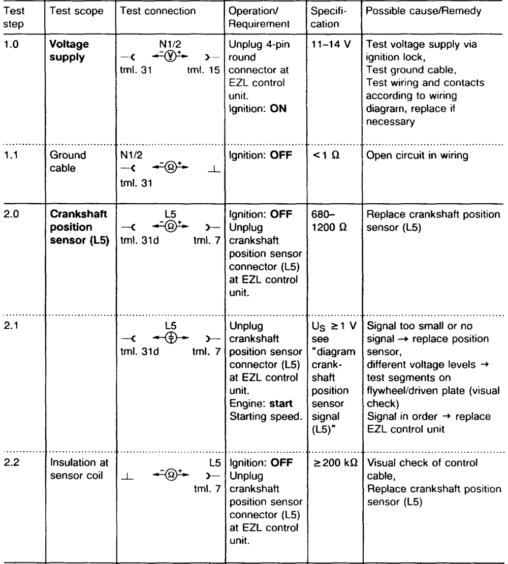
iim §=RA 15.1132-1250/7
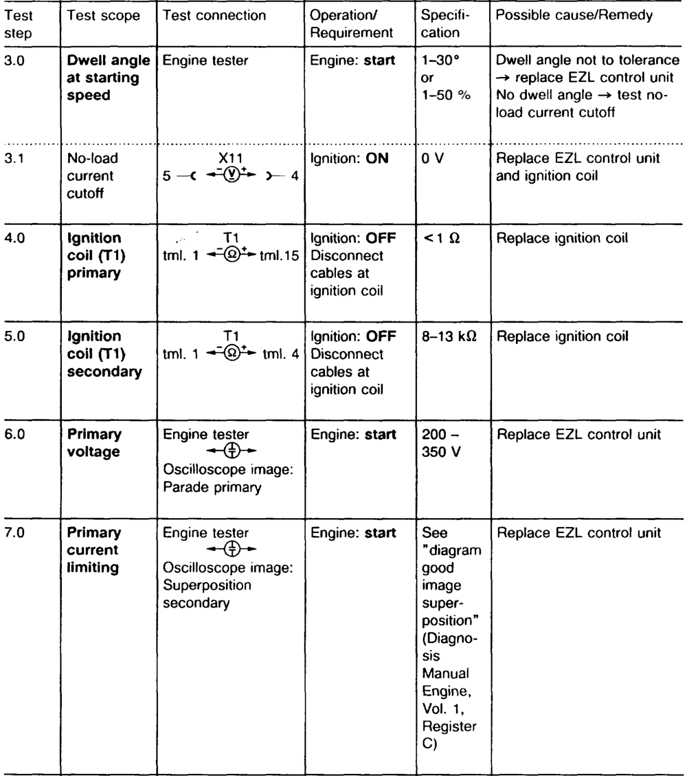
wie §=RA 15.1132-1250/8
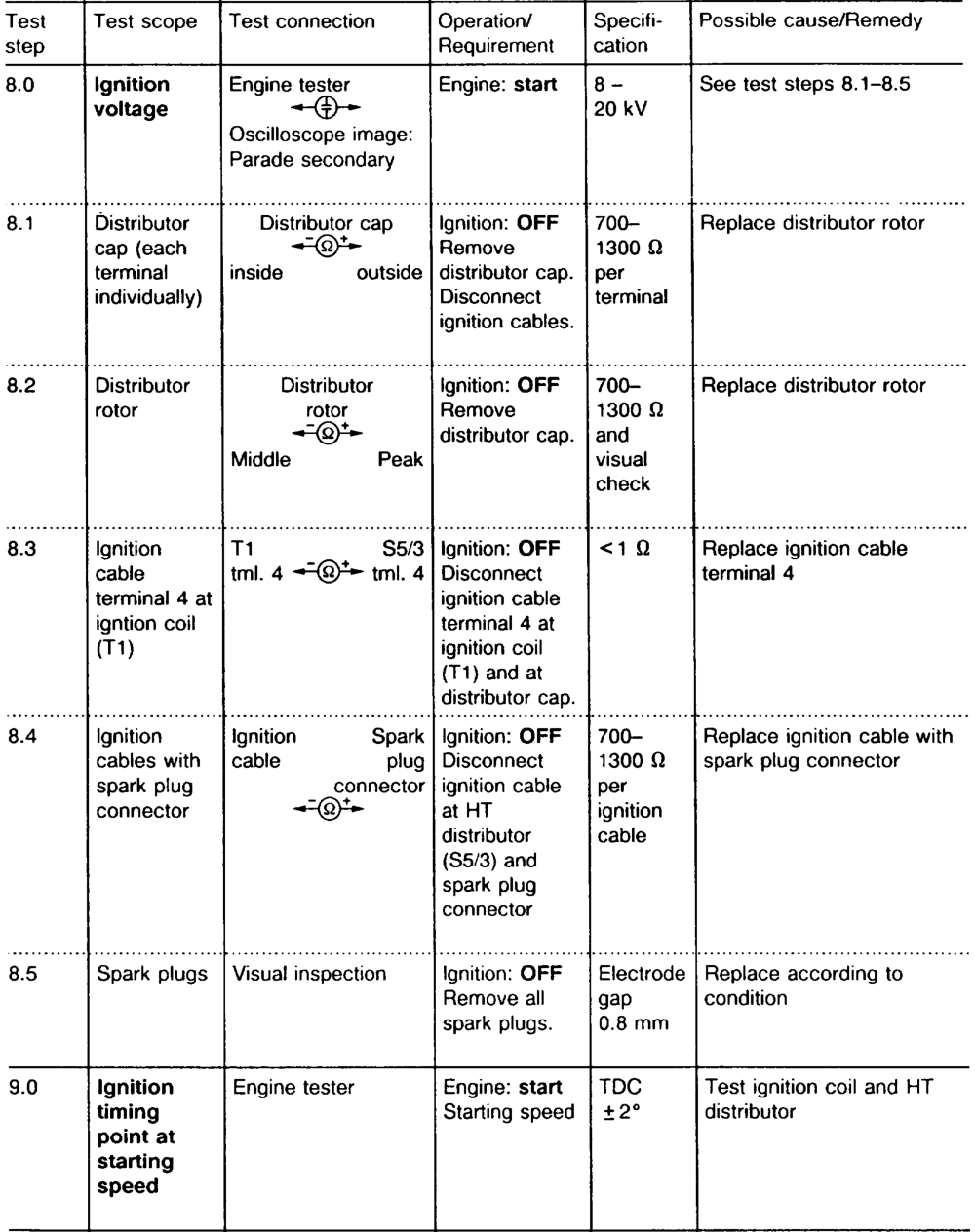
tie §=RA 15.1132-1250/9
b) Engine running
Symbols for testers
Symbols for test mode with multimeter
— Contact Multimeter _—- Connector Resistance mode =@~ Oscilloscope
Preconditions for test
Engine at operating temperature. Pay attention to notes for work on breakerless © Coolant temperature <95 °C. transistorized ignition system (15-0505). e@ Test ignition timing point at idle speed. © Test ignition timing point at 3200/min with
Note and without vacuum (detach vacuum line at If the specification of a main test step, e.g. test EZL control unit). step 2.0, is in order, continue with the next Pay attention to resistance trimming plug main test step, e.g. test step 3.0. position. If the specification of a main test step, e.g. test Switch off engine during test only if stated. step 2.0, is not achieved, continue test with sub-test step, e.g. test step 2.1.
See appropriate wiring diagram volume for wiring diagrams.
wiime =RA 15.1132-1250/10
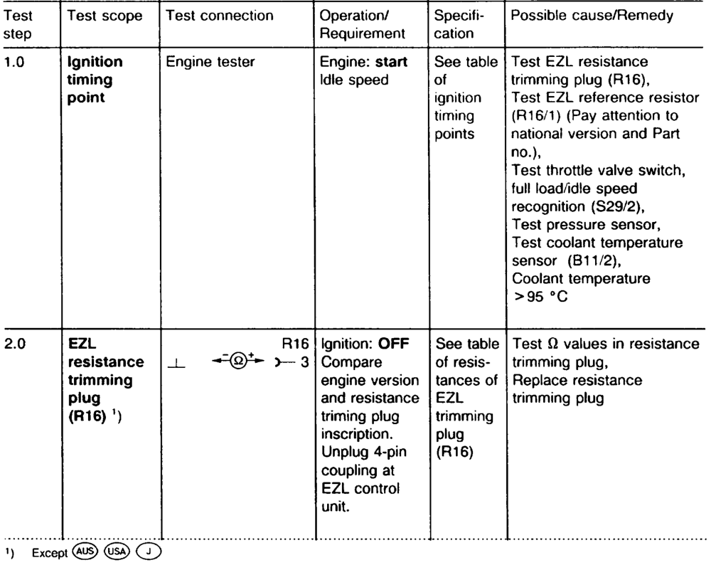
tie §=RA 15.1132-1250/11
iim RA 15.1132-1250/12
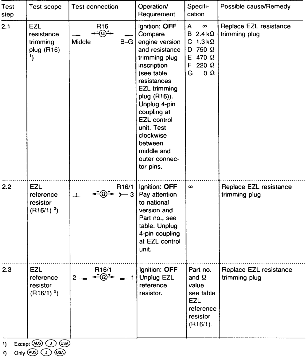
| Test | Test scope | Test | Operation/ | Specifi- | Possible cause/Remedy |
| step | Requirement | cation | |||

Ignition: OFF
3.0 Throttle Idle Adjust or replace throttle valve switch,
valve
position t+ Rectify open circuit in
switch, full
approx. 0Q. wiring according to wiring
load/dle
Full load
speed
diagram
recognition
approx. (S29/2) 02. Part load position 00, See also table ”resistances at throttle valve switch full load/ idle speed recognition (S29/2)”
4.0 Pressure Engine Vacum line at When Check vacuum line from EZL control intake manifold to EZL
sensor
vacuum contro! unit for leaks. unit disline conIf no fault found, replace connected. nected, Coupling ignition EZL control unit. disconnected timing from throttle point valve switch. must Engine: start advance. Engine speed/ gear lever position: idling.
wii §=RA 15.1132-1250/13
| Test | Test scope | Test | Operation/ | Specifi- | Possible cause/Remedy |
| step | Requirement | cation | |||

5.0 Coolant Q values, Replace cable according to Ignition: OFF tempera- 1 Unplug 4-pin wiring diagram. see diacoupling at grammed Replace coolant tempera-
ture sensor
(B11/2) EZL control coolant ture sensor (B11/2) unit, test Q temperavalues at two ture temperatures sensor (2/4-pin)
Example: + 20°C 2.282.72 kQ
+ 80°C 290— 364 2
| 6.0 | Ignition timing point | Engine | Detach vacuum line at EZL control unit. Engine: start | See table ignition timing points | Replace EZL ignition control unit |
| 7.0 | Dwell angle at 3200 rpm | Engine | Vacuum line and 4-pin coupling EZL control unit connected. Engine: start | 24–53° | Replace EZL ignition control unit |
etiam =—RA 15.1132-1250/14
| Test | Test scope | Test connection | Operation/ | Specifi- | Possible cause/Remedy |
| step | Requirement | cation | |||
Distributor cap, mechanical
HT Visual check
Ignition: OFF
8.0 damage in HT distributor,
distributor
Remove ($5/3) replace HT distributor if distributor cap. necessary. A Pay close attention to safety notes (15-0505).
Ignition: OFF
1kQ Replace faulty parts
Interfer-
9.0 Remove
ence
distributor cap.
supression
Measure
resistors,
distributor
resistances
cap, distri-
individually.
butor rotor,
spark plug
connector
Ignition
Ignition: ON
Good/ 10.0 Engine tester Replace ignition coil
Engine: start
coil
poor, see Oscilloscop image: Idle speed analyzing Parade oscilloscope image (Diagnosis Manual, Engine, Vol. 1, Register C).
‘) Ignition voltage: (average value) 6 – 16 kV. Difference of cylinders to each other <3 kV. Ignition voltage rise: the ignition voltage measured at idle speed must rise by not more than 6 kV when engine speed is increased up to 3000 rpm by bhipping the throttle. Combustion curve starting point: 0.6 — 1.2 kV. Difference of the cylinders to each other <0.3 kV. Combustion time: 1.9 – 2.5 ms. Difference of the cylinders to each other <0.3 ms.
tie §=RA 15.1132-1250/15
Location of components
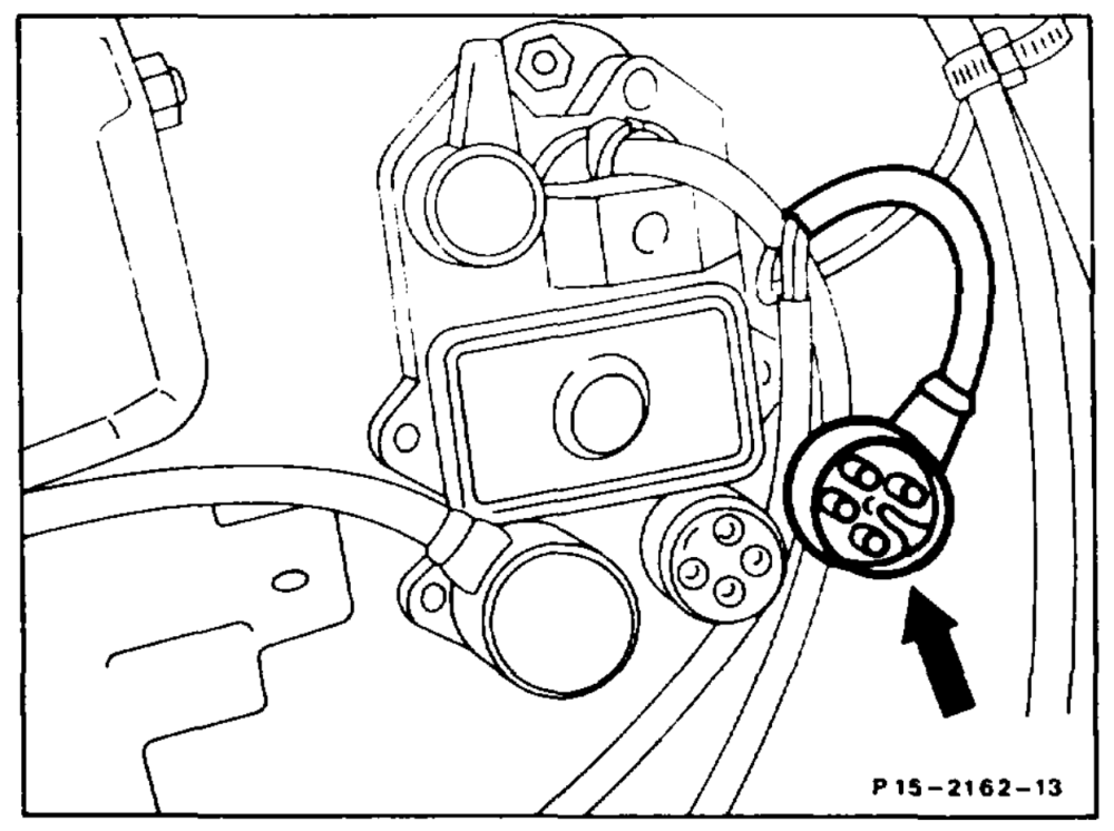
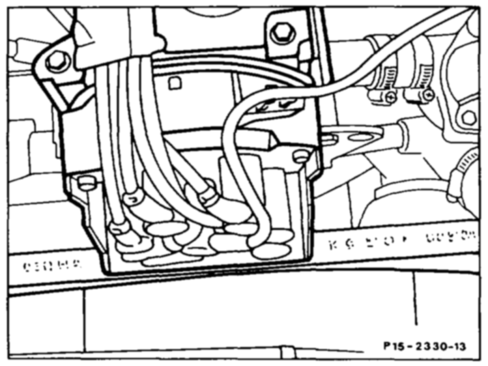
Round power supply connector at EZL ignition control unit (N1/2)
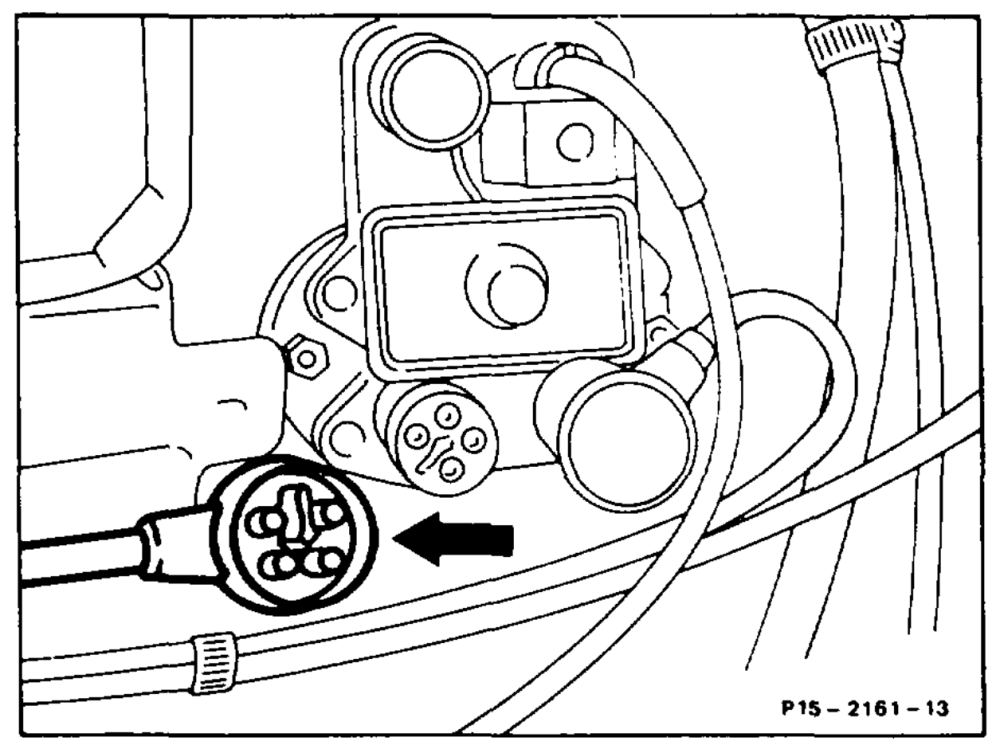
EZL ignition control unit (N1/2)
Arrow = 4-pin connector sensor
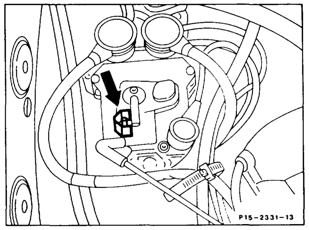
EZL ignition control unit (N1/2)
Arrow Vacuum line
tie §=RA 15.1132-1250/16
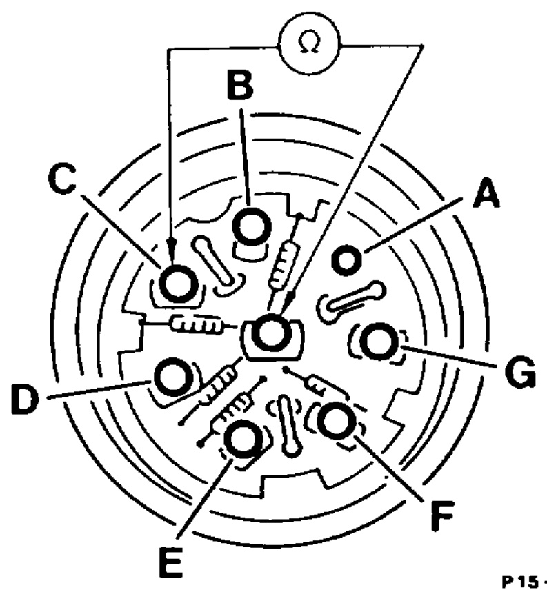
EZL resistance trimming plug (R16)
A – B 2.4 kQ Cc 1.3 kQ D 0.75 kQ E 0.47 kQ F 0.22 kQ G 0 kQ
P1S—2144–13
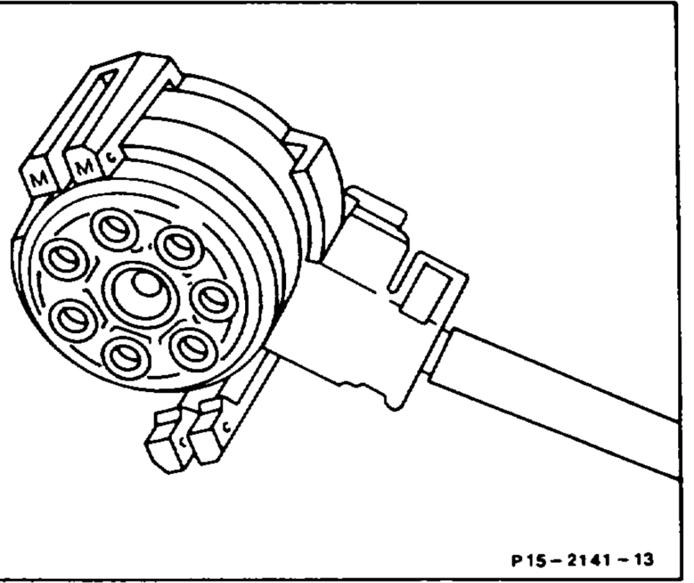
Bottom part of connector, EZL resistance trimming plug (R16)
EZL reference resistor (R16/1) Part no. Resistance National version
000 540 22 81 220 Q @S) 000 540 24 81 750 Q @ SSO
P15–2189–13
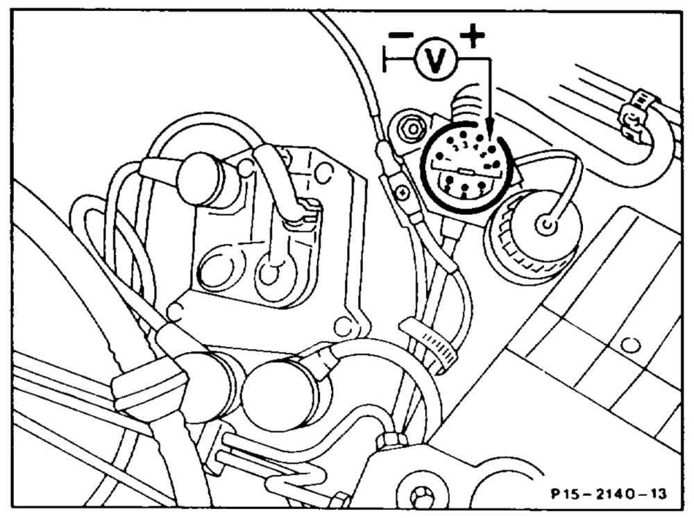
Diagnostic socket/terminal block (X11)
Terminal TN
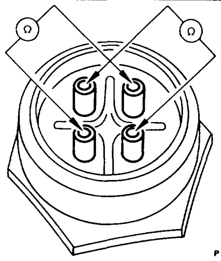
EZL/KE, LH) coolant temperature sensor, 4-pin (B11/2)
P15-0171~13
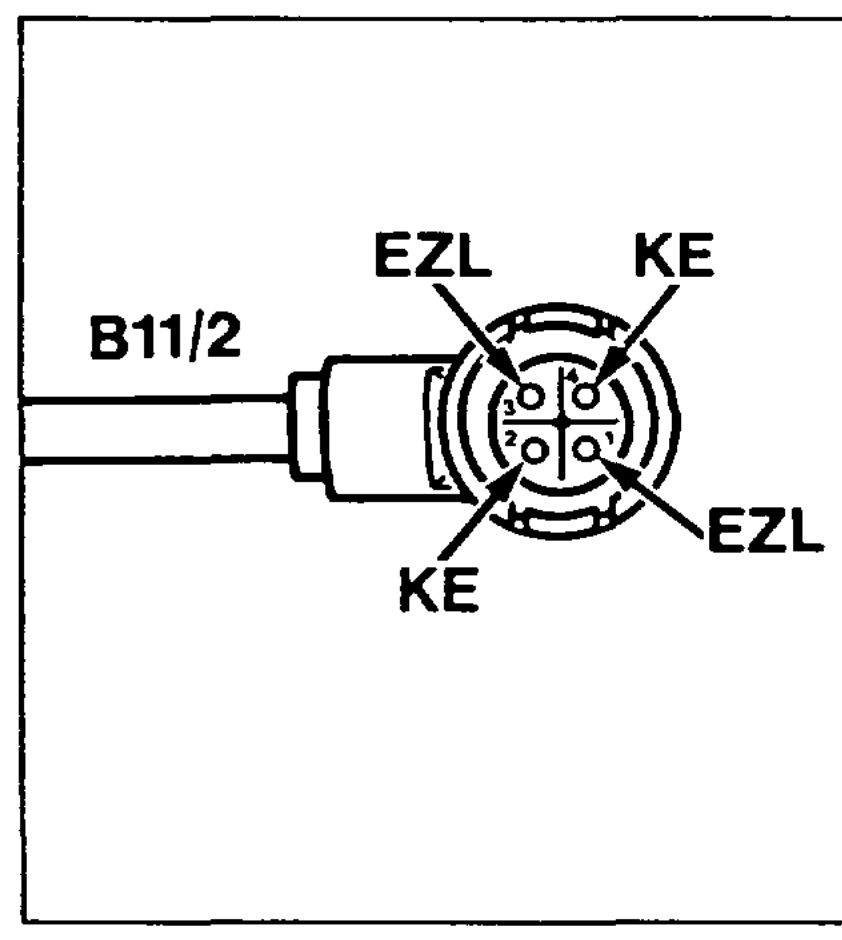
Connect 4-pin connector, coolant temperature sensor (B11/2)
Pin assignment (positions stamped in connector) EZUAKR temperature 1 sensor KE temperature sensor 2 Ground, EZL/AKR ignition 3 control unit PO7~2022–13 Ground, KE control unit 4
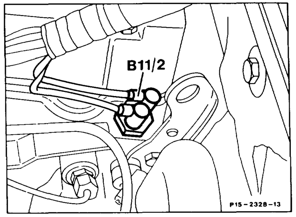
Coolant temperature sensor (B11/2), 2-pin
wii =RA 15.1132-1250/18
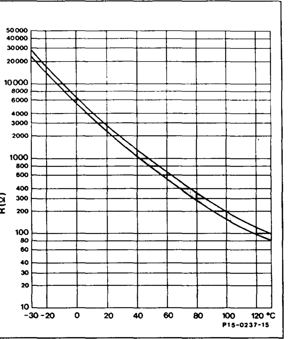
Diagram, coolant temperature sensor (2/4-pin)
High voltage distributor (S5/3)
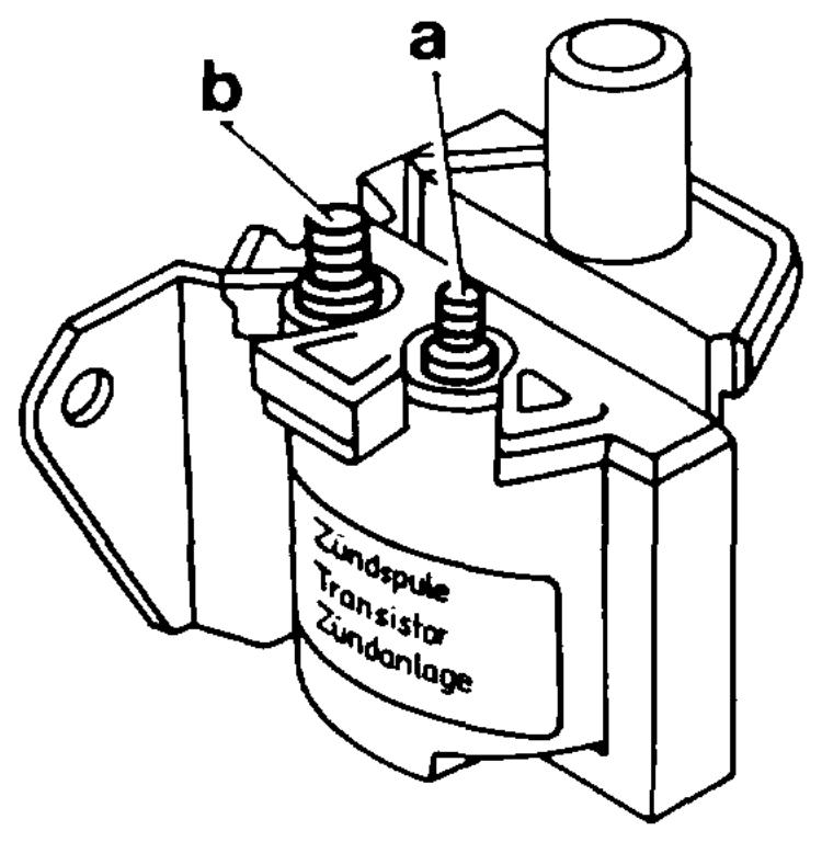
Igition coil (T1)
a Terminal 1 b Terminal 15 P15 5064 -13
wim §=RA 15.1132-1250/19
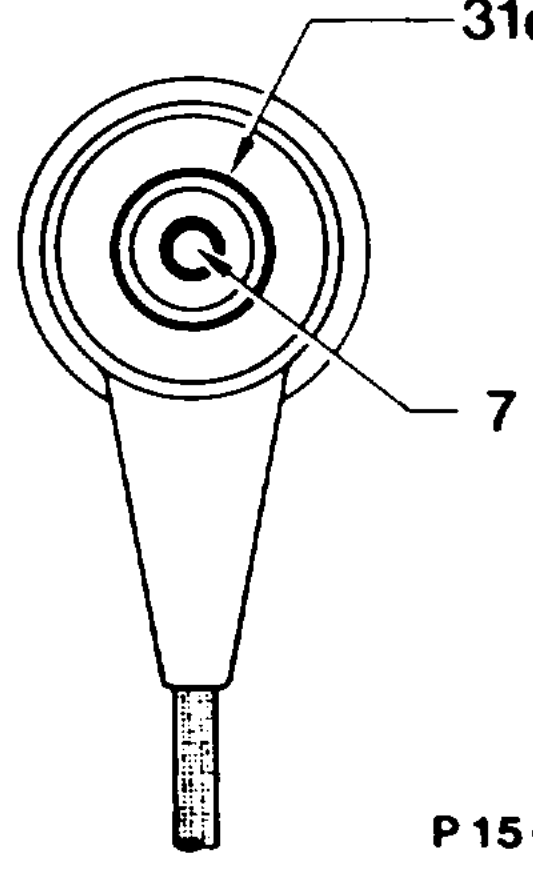
Connector, crankshaft position sensor (L5)
P15-0240–13
Diagram, crankshaft position sensor (L5) signal
1 2h 12 43. Us-
/ eee
Usan d P15-0400–13
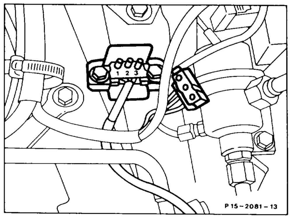
Plug connection, throttle valve switch full load/idle speed recognition (S29/2×1)
| speed recognition (S29/2) | peeeeen $ 29/2 | ||
| Idle le spee speed | approx. 02 | oY Oo, ee Fag | |
| Full load | approx. 0 | Q 0s „mommy OT | |
| PO7-0363–11 | |||
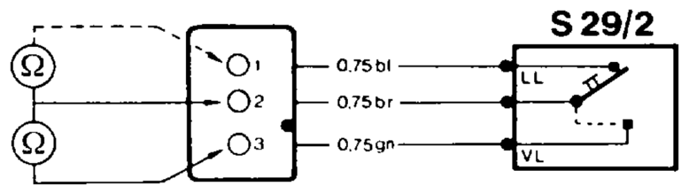
LL \dte contact VL Full load