Removing and installing belt pulley/vibration damper and hub
WIS 03-3420
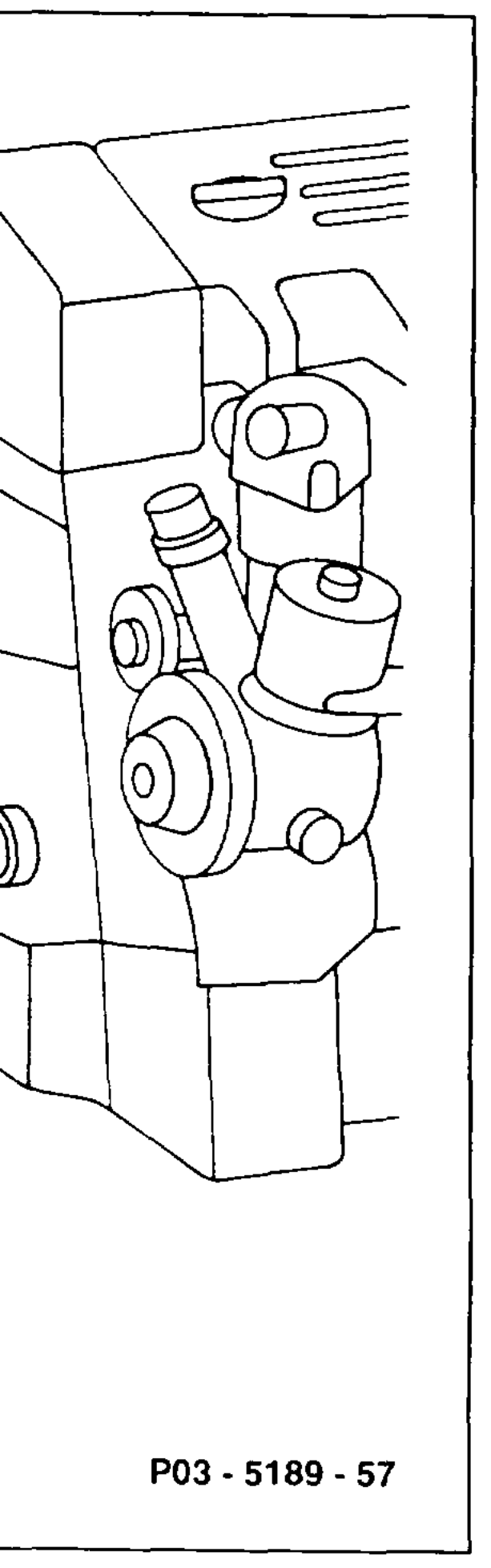
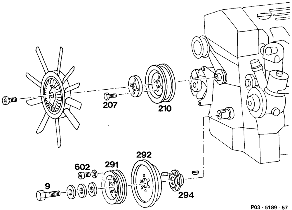
Preceding work: Operation no. of operation texts and work units or standard texts Bottom engine compartment panel removed (Maintenance and flat rates Manual 2, op. item 6190). 03-1320 – 03-1911 Models 107, 124, 126, 201: radiator removed (20-4200). Model 129: fan shroud removed (20-3400). Viscous fan clutch removed (20-3120).
Guard plate at radiator or condensor ……… attach (step 1). Crankshaft cylinder1 ……………—4rotate to TDC (step 2). Bolts (207) belt pulley (210) fan slacken, tighten (10 Nm) (step 3). Poly-V-belt 2.0.0.0… eee eee remove, install (13-3420). Belt pulley (210) of fan …………….2.-. remove, install (step 5). Holding lock for crankshaft/ring gear ……… remove, install (03-5000). Belt pulley (291) and vibration damper (292) 0.0.0.2 eee eee remove, install (step 7).
«aim §=RA 03.1123-3420/1
Bolt (9) of hub 2. eee unscrew, screw on 300 Nm (step 8). Hub (294) with puller 103 589 003300 ……. pull off, press on (step 9).
Tightening torques in Nm
| Bolts of vibration damper to hub | 25 |
| Bolt of hub to crankshaft | 300 |
Modified washers for vibration damper and
belt pulley at hub
Harder washers are used to achieve greater security against bolts slackening.
Production breakpoint: 05/1985
Mode! Engine Engine end no. manual automatic transmission transmission
124.030 103.980 000758 003040
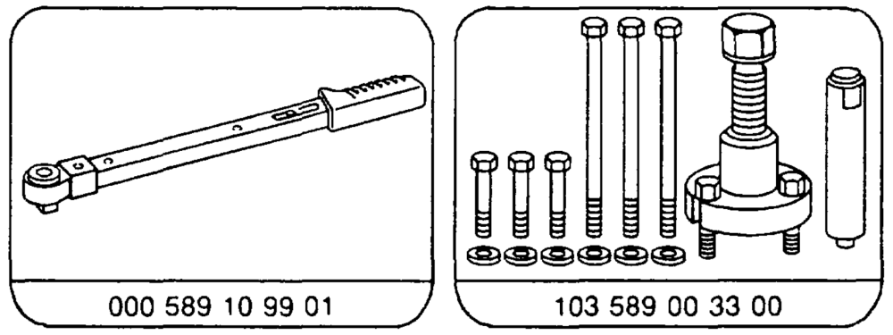
Special tools
qui §=RA 03.1123-3420/2
Shop-made tool
Guard plate for radiator/condensor Dimensions: approx. 680 x 480 x 1
Note
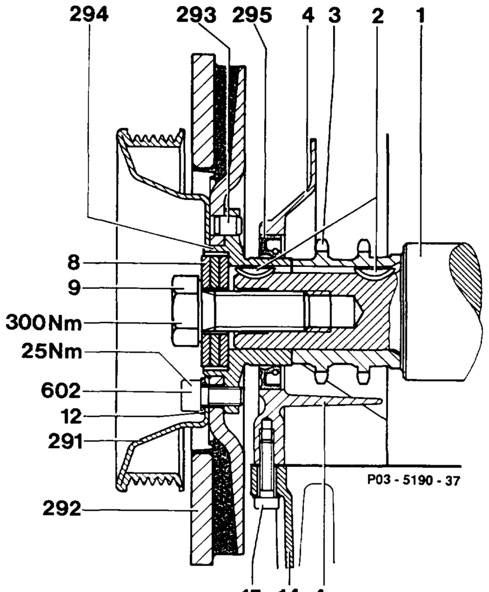
Belt pulley, vibration damper and hub can be replaced without balancing.
15 14 4a
1 Crankshaft 14 Oil sump
2 Woodruff key 15 Bolt
3 Crankshaft gear 291 Belt pulley
4 Timing case cover 292 Vibration damper 4a Timing chain lock 293 Straight pin
8 Dished springs (3 ea.) 294 Hub
9 M18 x 1.545 bolt 295 Radial seal
12 8.4 washer 602 M8 x 18 bolt
tie §=RA 03.1123-3420/3
1 Attach guard plate to radiator or condensor of air conditioner.
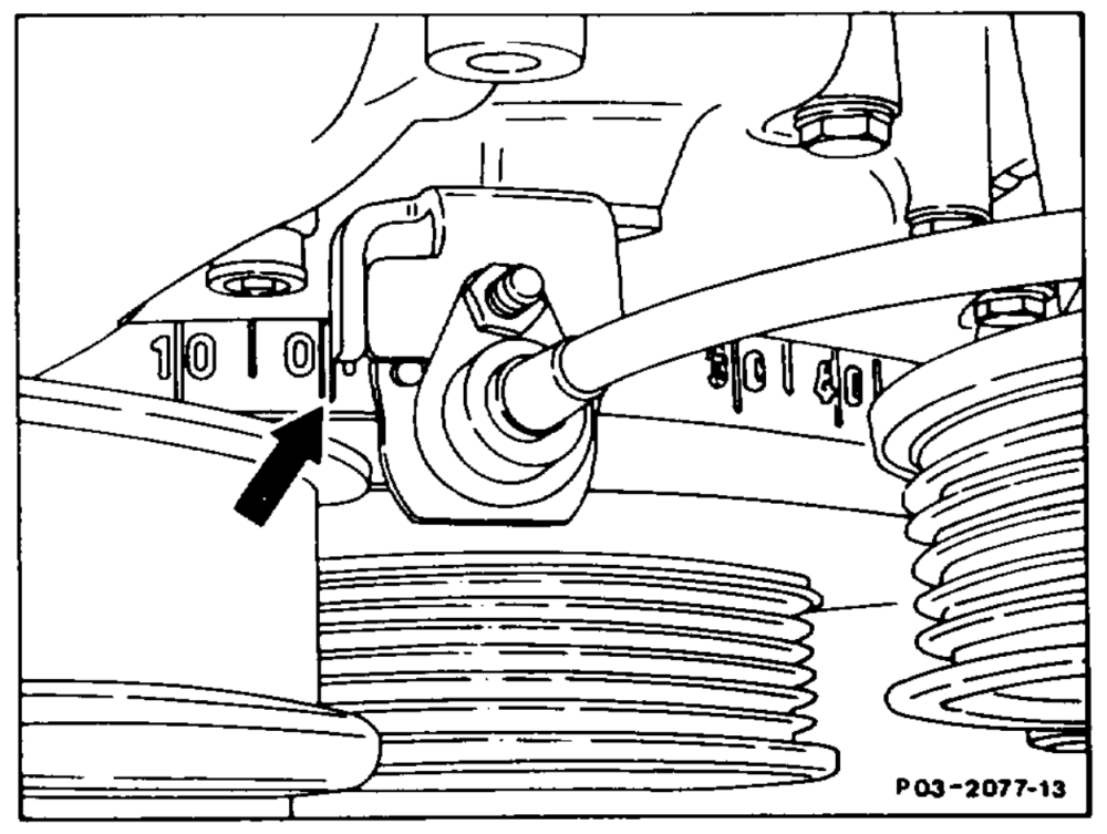
2 Rotate crankshaft cylinder 1 to TDC (arrow) so that the Woodruff key in the crankshaft is facing up vertically.
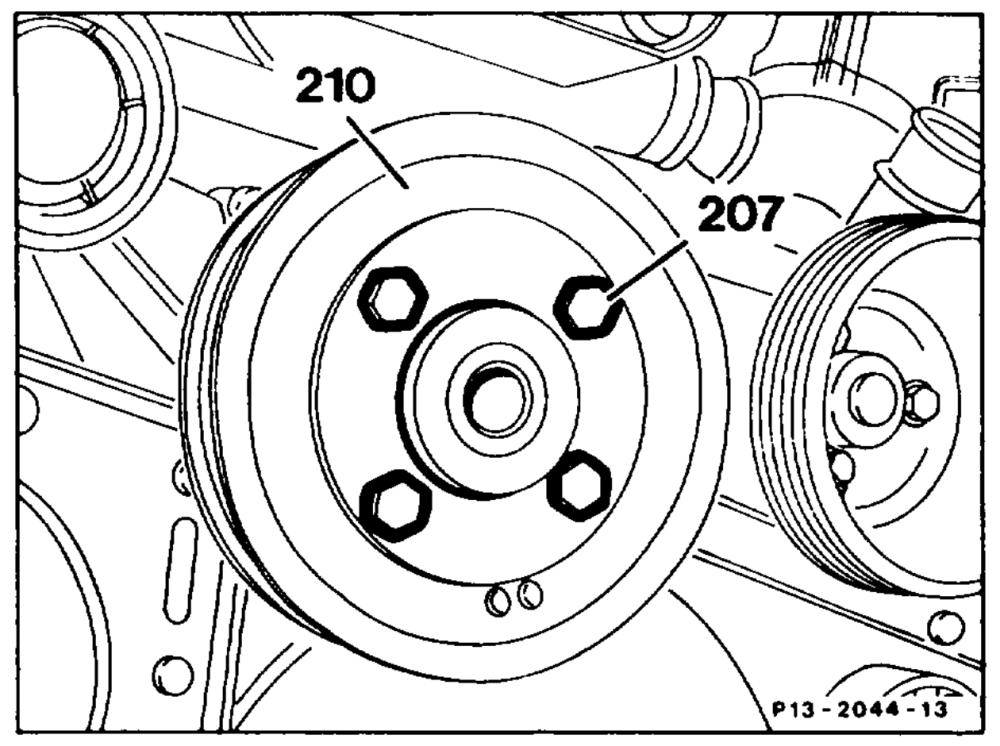
3. Slacken bolts (207) of belt pulley (210) of viscous fan clutch. Tightening torque 10 Nm.
4 Remove poly-V-belt (13-3420).
5 Unscrew belt pulley (210) of viscous fan clutch and remove.
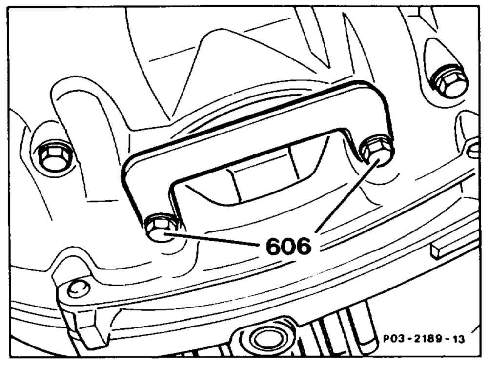
6 Install holding lock for crankshaft/ring gear (30-5000).
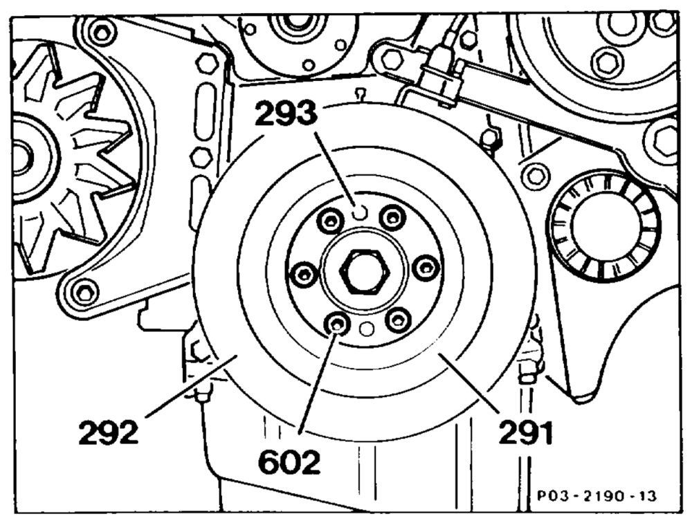
7 Unscrew bolts (602), take off belt pulley (291) and vibration damper (292).
Installation note
The vibration damper (292) is fixed in place with a dowel pin (293). Install bolts (602) with washers. Tightening torque 25 Nm.
8 Unscrew bolt of hub with 3 dished springs.
ay. Installation note Oil thread of bolt and dished springs. Fit on dished springs with curved side facing bolt head. Tightening torque 300 Nm.
Vo
PO3-0081–13
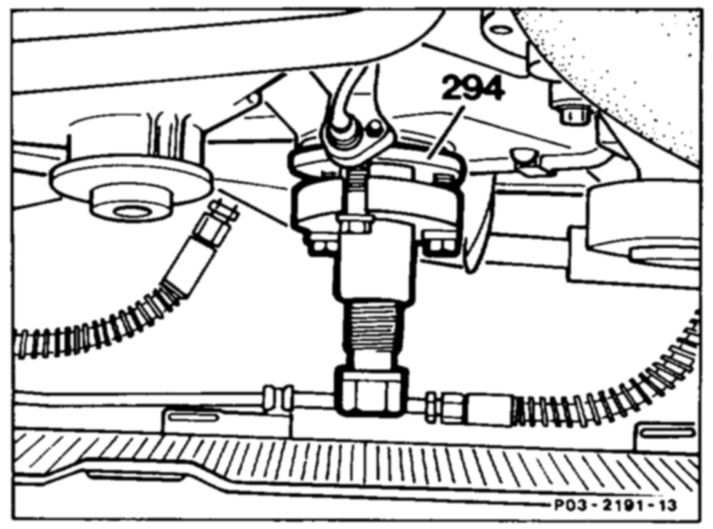
9 Remove hub (294) with puller 103 589 00 33 00.
Installation note
Heat hub (294) to approx. 50 °C so that it can easily be pushed onto the crankshaft. When pushing on, turn to determine whether the groove in the hub (294) is aligned with the Woodruff key in the crankshaft.
10 Install in the reverse order.
mime RA 03.1123-3420/5