Checking, correcting setting of TDC sensor
WIS 03-3450
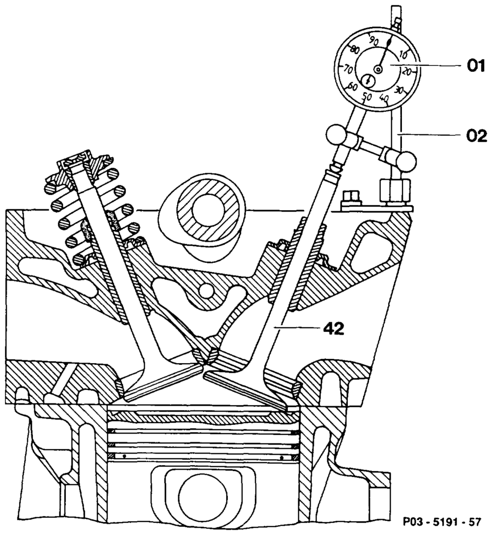
Preceding work: Viscous fan clutch removed (20-3120). Poly-V-belt removed (13-3420). Cylinder head cover removed (01-0500).
Checking setting of TOC sensor
Piston of cylinder 1 ………….-..-.-0.-. turn to 10° before ignition TDC (step 1). Valve spring at inlet valve of cylinder 1 …….. remove, install (05-250). Valve stem seal on inlet valve of cylinder 1 ….. remove, install (05-270). TDC sensor (L1) 2… ee ee eee ee eee remove, install (step 4). Dial gauge holder (02) 136 589042100 …… fit onto cylinder head (step 5).
igs =RA 03.1123-3450/1
Inlet valve (42) 2.2.0… eee ee eee fit onto piston crown. Dial gauge (01) 2.2.2… 2 eee eee eee insert into dial gauge holder (02) with 4 mm preload (step 6). Crankshaft ………….0002.0202000000rotate in direction of rotation of engine and set TDC at cylinder 1 with dial gauge (01). Large pointer of dial gauge (01) …………. set to 0”. Crankshaft 2.2.20… 00.00.20 2c eee eee ee rotate in direction of rotation of engine until dial gauge has moved back by the value, see table „piston travel” (20° after TDC cylinder 1). In this position 00… .0 002 eee insert fixing device 119 589 00 21 00 into adjusting slide (step 10). Fixing device 119 589 00 21 00 must engage into measuring pins ………-………00–5 on vibration damper (step 11).
Cap of cooling system …………….—. open (release pressure). Heating water return line ……………-4. remove, install, replace seal (step 14). Opening of coolant pump seal. Screw of adjusting slide slacken (step 16). Move adjusting slide until fixing device 119 589 002100 eee eee eee engages at vibration damper. Screw of adjusting slide tighten. Coolant 22.0… 0. cee eee eee eee pour in (20-0100).
Piston travel at crankshaft position 20° after TDC of cylinder 1 in mm
| Measured via inlet valve | 3.31 |
| Measured vertically on piston | 3.07 |
wae §=RA 03.1123-3450/2
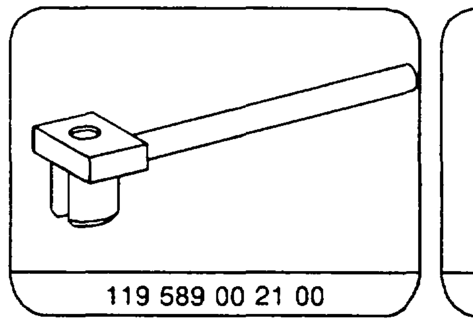
Special tools
2100 3 136589042100 Y/Y \ 001 589 53
Notes
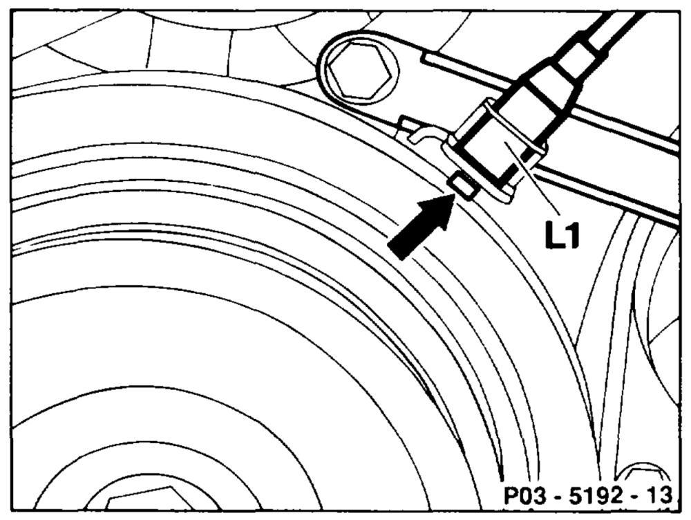
The TDC sensor (L1) with bracket is attached to the timing case cover. The measuring pin (arrow) in the vibration damper must be positioned in the middle below the TDC sensor (L1) in the setting 20° after TDC of cylinder 1.
The setting of the TDC sensor must be checked and corrected, if necessary: e After replacing the crankshaft or the vibration damper. e After replacing the timing case cover. After fitting parts to short engines.
Checking setting of TDC sensor
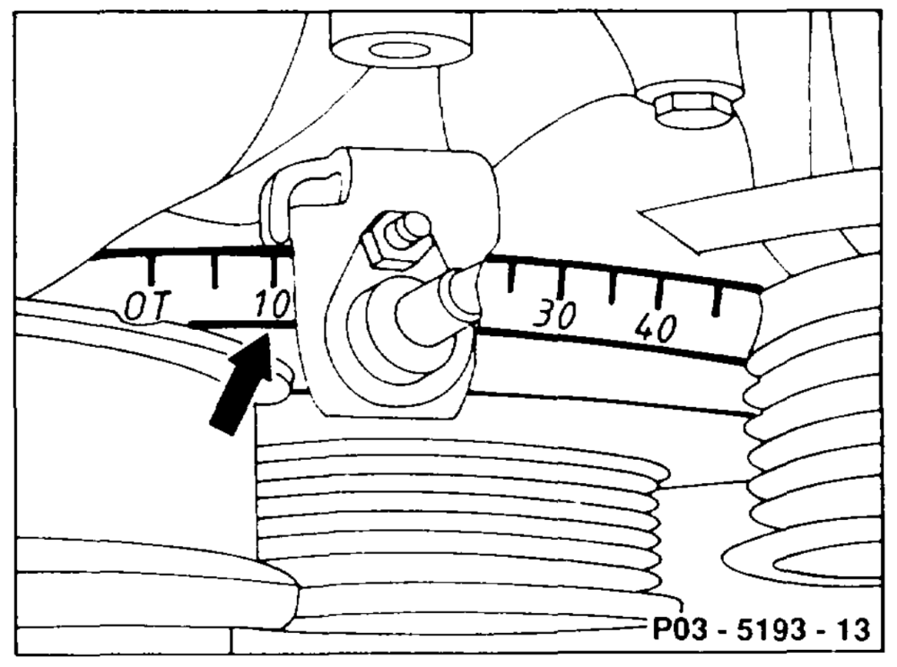
(with cylinder head in place)
Note With cylinder head removed, attach a dial gauge holder to the crankcase and position dial gauge pin vertically on the piston crown.
1 Set piston of cylinder 1 to 10° before ignition TDC (arrow).
2 Remove valve stem seal at inlet valve of cylinder 1 (05-2700).
emis §=RA 03.1123-3450/3
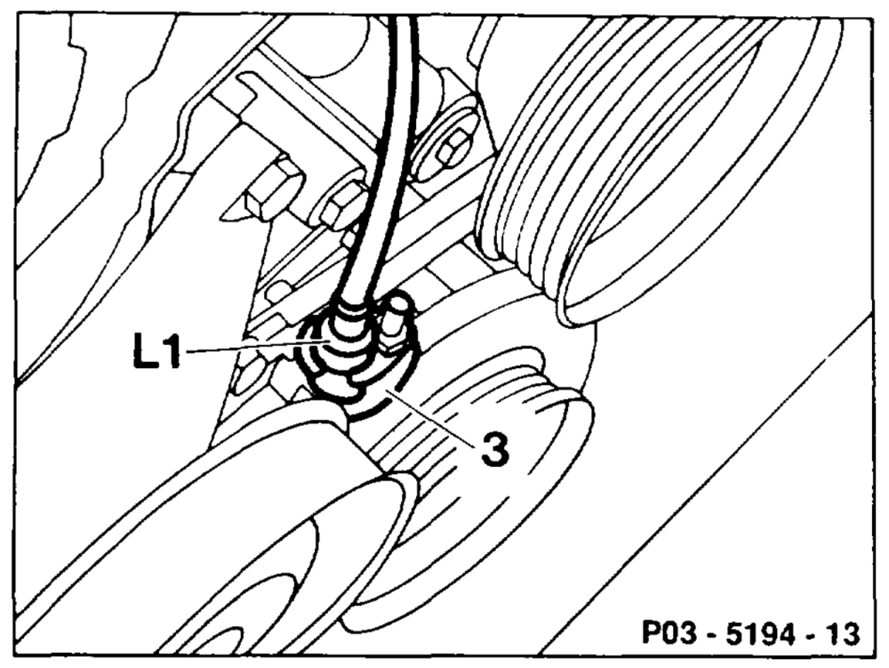
3 Unscrew TDC sensor (L1) and pull out of setting slide (3).
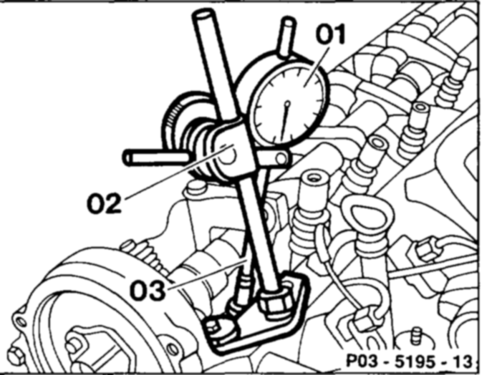
4 Attach dial gauge holder (02) 136 589 04 21 00 to cylinder head.
5 Fit inlet valve onto piston crown.
6 Insert dial gauge (01) with dial gauge extension (03) into dial gauge holder (02) with a preload of 4 mm.
7 Rotate crankshaft in direction of rotation of engine and set TDC at cylinder 1 with dial gauge (01).
8 Turn scale of dial gauge until the large pointer of the gauge (01) is set to ”0”.
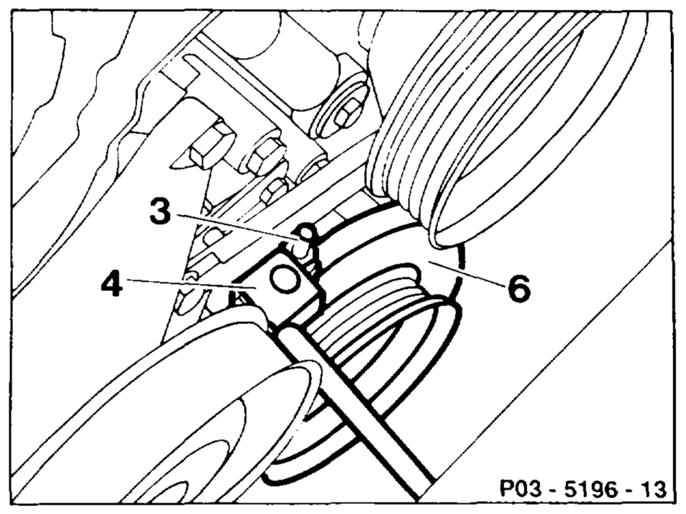
9 Turn on crankshaft in direction of rotation of engine until dial gauge has moved back by the appropriate value (piston travel).
10 Insert fixing device (4) 119 589 00 21 00 into the setting slide (3).
11 The groove of the fixing device (4) must engage in the measuring pin on the vibration damper.
12 If the fixing device (4) does not engage at the vibration damper (6), correct setting of TDC sensor.
amie RA 03.1123-3450/4
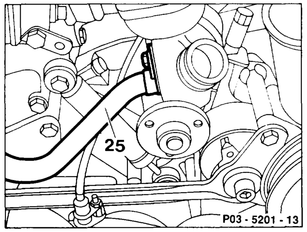
Correcting setting of TDC sensor (L1)
13 Open cap of cooling system (release pressure).
14 Unscrew heating water return line (25) at -coolant pump and fan bearing bracket and place to the side with cable connected.
Installation note
Replace O-ring between heating water return line (25) and coolant pump.
15 Seal opening in coolant pump.
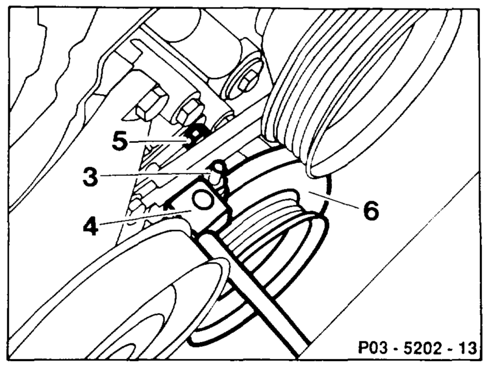
16 Slacken bolt (5) and move setting slide (3) until fixing device (4) engages in the measuring pin on the vibration damper (6).
17 Tighten bolt (5).
18 Install in the reverse order, starting with step 16.
19 Pour in coolant (20-0100).