Removal and installation of front engine mounts
WIS 00-211
Tightening torques
Bolts for engine bearer at engine mounts M 12 70 (7) 123. (type 123.1) M 10 40 (4)
Bolts for engine mounts at front axle beam (type 115.1) 30 (3)
Special tools
Torque wrench handle 20–100 Nm (2–10 kpm) – 001 589 35 21 00
Torque wrench handle 50–200 Nm (5–20 kpm) 4 – 001 589 44 21 00
Attachable ratchet, 1/2” drive for 7’ torque wrench handle x Poco 00 = 1 589 42 09 00
Shop-made tool
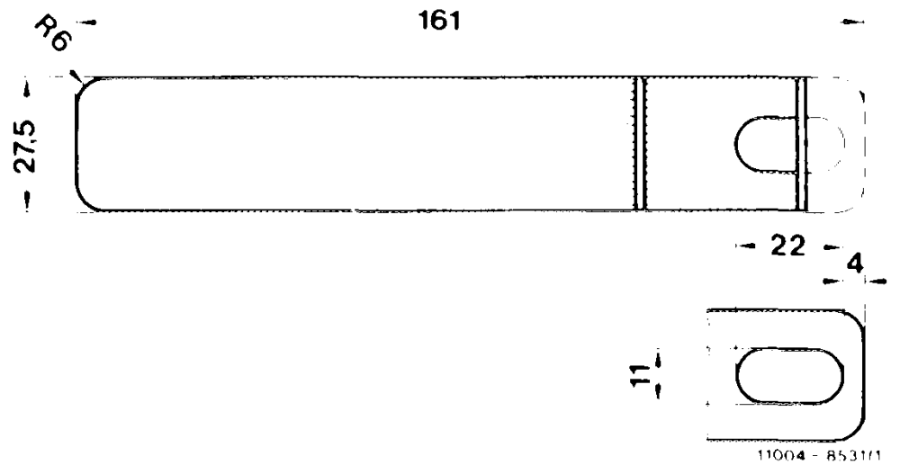
114.5 315°05150 35 i 9 3 3%) * 1s oF t — ua ~—26 ——
| Gauge to adjust front engine | front engine ae – |
| stop (type 123.1) | 1) nK ( |
Note
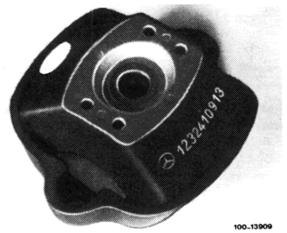
The engine mounts differ in Shore hardness.
They can be distinguished not only by the parts Nos. but also by colored dots.
The engine mounts for type 115.1 cannot be installed in type 123.1, and vice versa.
Type Version Engine mount left Engine mount right Part No. Part No.
115.110 115 241 07 13 without air615 223 01 12 115.115 (two yellow dots) conditioner 116.117
115 241 08 13 115.114 (blue dot)
115.110 107 241 09 13 with air615 22301 12 115.115 (yellow dot) conditioner 115.117
115 241 07 13 615 22301 12 (two yellow dots) 115.110 115.117 nly @ 107 241 09 13 615 223 01 12 (yellow dot)
123.102 123.103 123 241 09 13 (blue dot) 123.120 replaced by 123.123 123.125 123 241 17 13 123.126 123.183
123.130 123 241 1013 123.132 (white dot) 123.150 123.190
123 241 12 13 123.123 only Gs) G) (two green dots)
123.130 123 241 16 13 123.150 only Ga) Go) (white dot) 123.190
A. Type 115.1
Removal
1 Unscrew engine bearer bolts (20) at engine mounts, working from above.
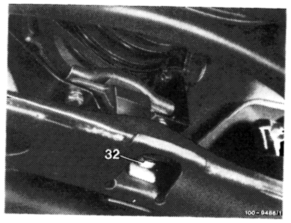
2 On types 115.110 and 115.115, release engine stop by unscrewing nut (32) and withdrawing bolt.
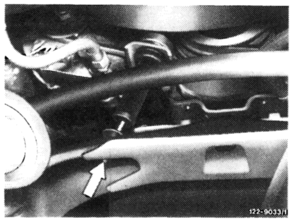
engine shock absorber at bottom (arrow). To do so, secure piston rod at place provided for this purpose, using a screwdriver.
4 Raise engine, applying inspection pit lift to oil pan.
Note: Insert wood support to avoid damage to oil pan.
5 Unscrew bolts (20) and withdraw engine mount with shim (26).
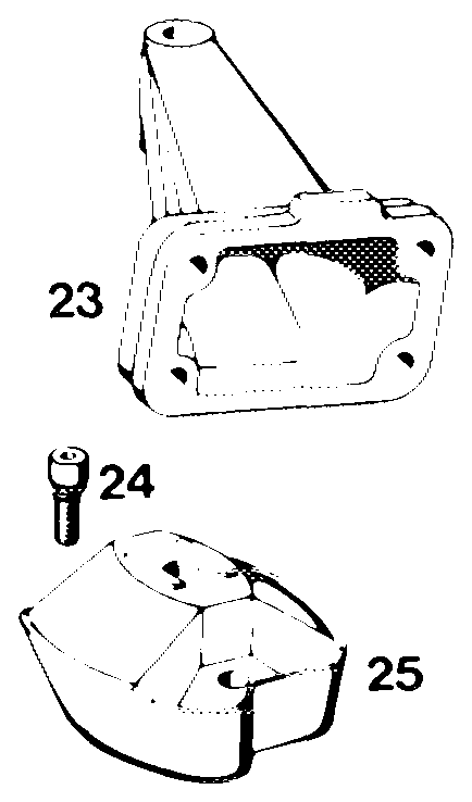
Note: Shim (26) is to be found only on engine mounts as per part Nos. 115 241 07 13, 08 13 and 107 241 09 13.
20 Bolt M12 x 55 21 Spring washer B 12 22 Shield (right) 23 Engine bearer 24 Screw assembly M 8 x 18 25 Engine mount 2 26 Shim ~—”1222-5437/2
Installation
6 Apply and fasten engine mount with shim.
7 Lower engine. For types 115.114 and 115.117, pass engine shock absorbers through crossmember.
8 Bolt engine bearer to engine mount.
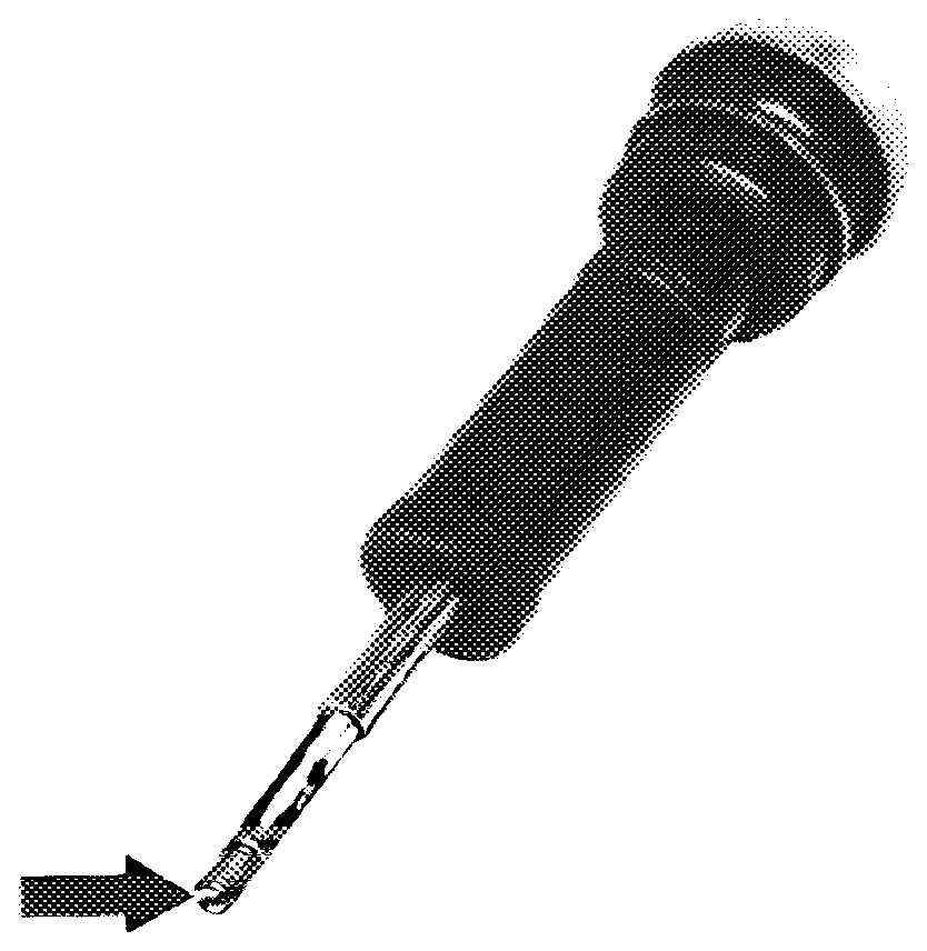
shock absorber at bottom, securing piston rod at appropriate position (arrow) with a screwdriver.
10 For types 115.110 and 115.115, bolt engine stop in position.
11 Adjust engine stop (00—220).
B. Type 123.1
Removal
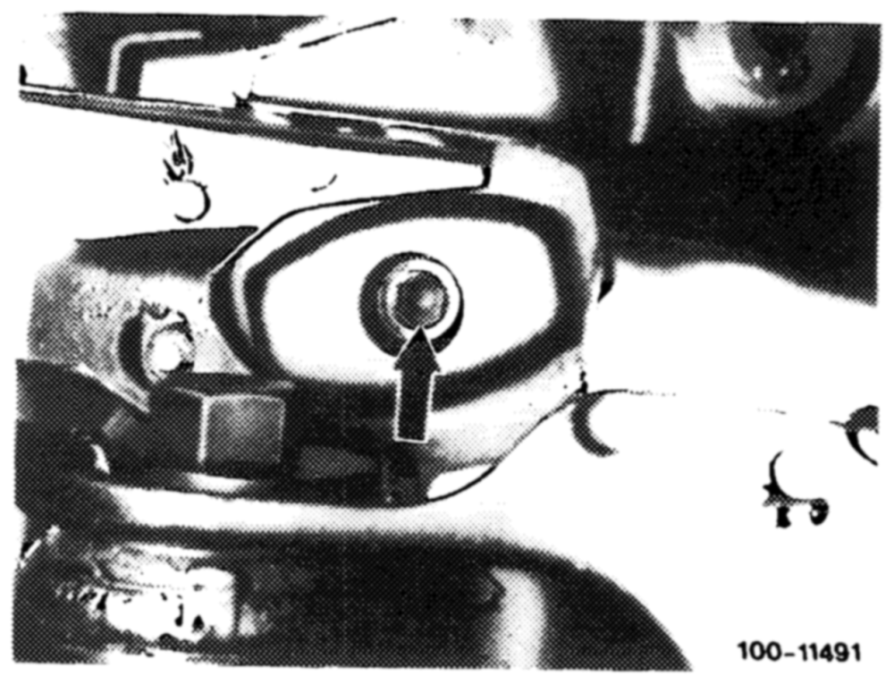
1 Unscrew engine bearer bolts (20) at engine mount, working from below (arrow).
Caution: There are two bolt versions:
1st version M 12 x 35 2nd version M10x 40
The tapped hole in the engine bearer has been modified accordingly.
2 Turn steering to full left or right lock.
3 Raise retainer (30) at front engine stop and swing away to one side.
Caution: Types 123.105/130/132/150/190 with two engine shock absorbers do not have engine stops.
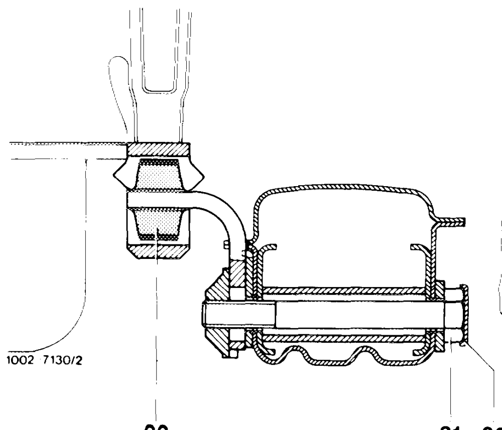
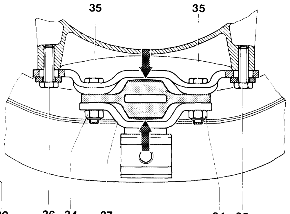
4 Unscrew adjusting screw (31).
33 31 30 36 34 08637 34 36
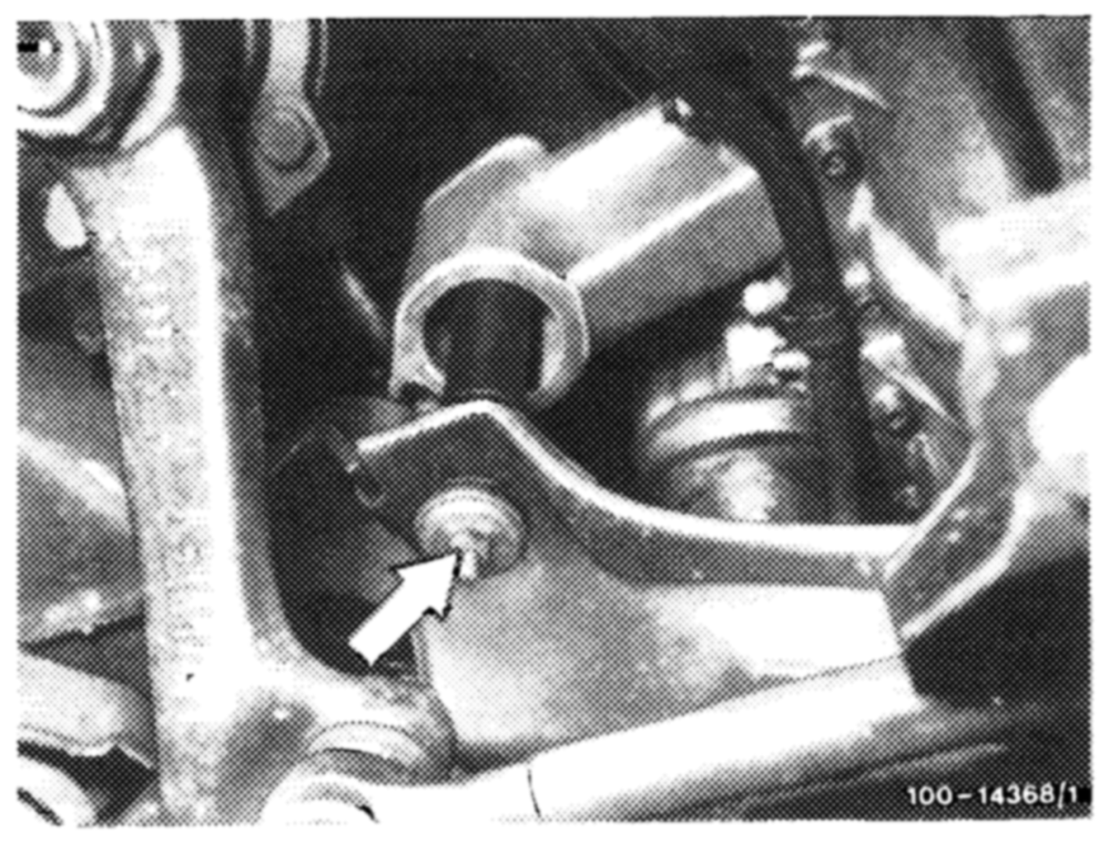
lower nut (arrow).
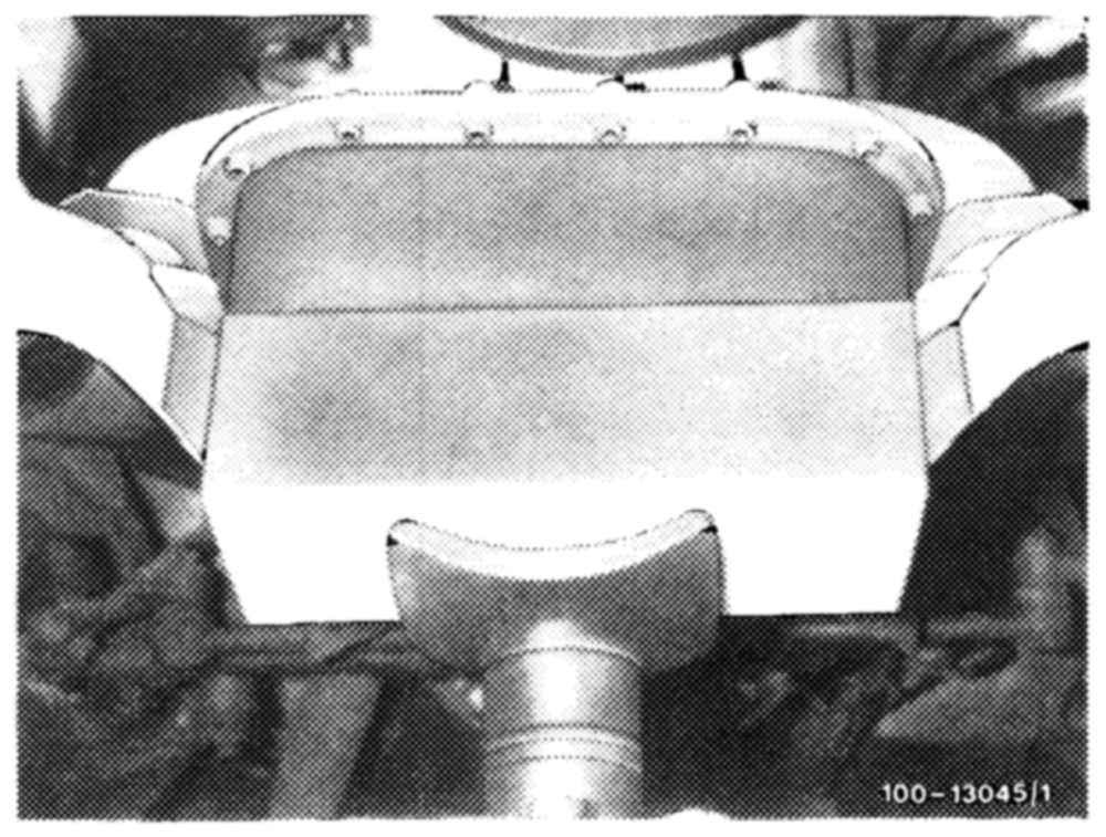
To do so, secure piston rod at place provided for this purpose (illustration, item 13).
6 On models with power steering, connect return hose to power steering system. To do so, draw oil out of power steering pump reservoir.
7 Raise engine, applying inspection pit lift to oil pan.
Note: Insert wood support to avoid damage to oil pan.
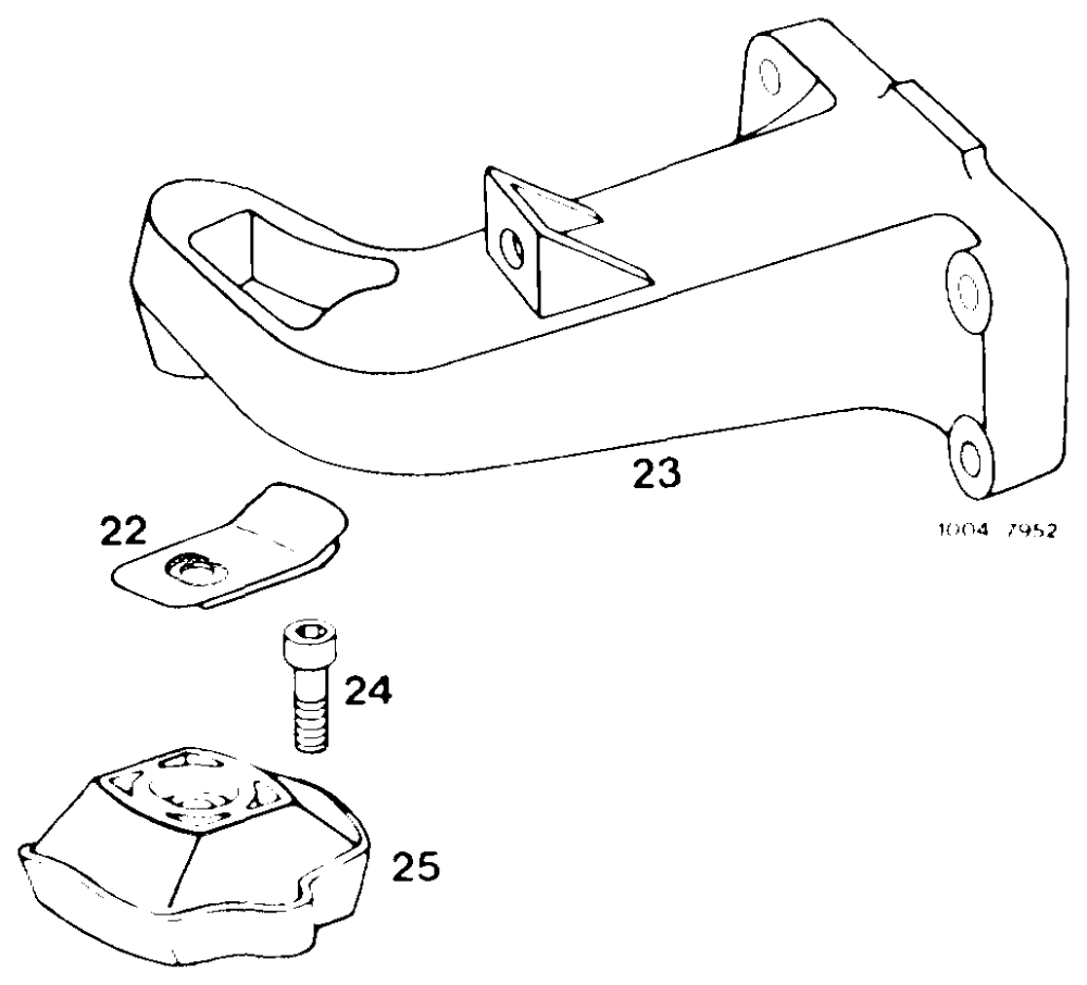
8 Withdraw shields (22).
9 Remove screws (24) and withdraw engine mount.
20 Bolt M 12 x 35 or M 10 x 40 22 Shield 23 Engine bearer 24 Screw assembly M 8 x 18 25 Engine mount
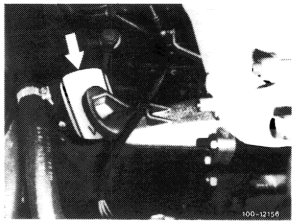
11 Insert shields.
Note: Note correct mounting location.
12 Lower engine. Make sure to pass engine shock absorber through crossmember.
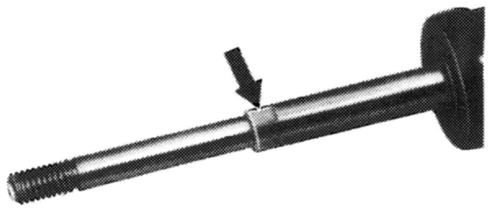
13 Apply bolts (20) and torque to 70 and 40 Nm, respectively (7 and 4 kpm, respectively).
14 Tighten engine shock absorber at bottom, securing piston rod at place provided for this purpose (arrow).
15 Adjust engine stop (00—220).
16 If new engine mounts have been fitted, remember to re-adjust engine stop after 500-1000 km and 5000 km (00—220).