Replacing altitude adjusting box
WIS 07.1-225
A. Mechanical altitude adjusting box engine 617 @s® model year 1975/76
Any damage on altitude correction instrument can be repaired only on an injection pump test bench with injection pump removed.
Operation
The mechanical altitude adjusting box is a manually adjustable altitude correction instrument which restricts the full load contro! path.
The altitude correction provides no parallel displacement of control path, which means that during an adjustment of the altitude correction the max possible control path is restricted by means of a fixed stop. This will make compensation inoperative and the control path remains constant throughout entire speed range.
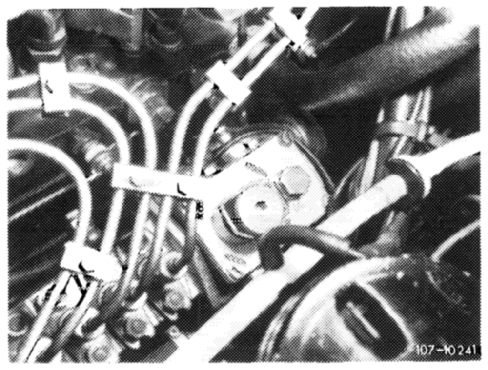
The correction screw can be adjusted stepwise from O—approx. 3,900 m (12,000 ft), each step amounting to approx. 650 m (2,000 ft).
Recommended adjustments: Up to approx. 650 m (2,000 ft) = position 0
from 650 m (2,000 ft) — 2,000 m = position 1,300 m
(6,000 ft) (4,000 ft)
from 2,000 m (6,000 ft) — = position 2,600 m
3,200 m (10,000 ft) (8,000 ft) from 3,200 m (10,000 ft) = position 3,900 m (12,000 ft)
Starting model year 1977
Operation
With increasing altitude above normal (decreasing air pressure) the two diaphragm boxes (12) will expand. Starting from a given atmospheric pressure the internal force of diaphragm box will become higher than the preload of the altitude box pretensioning spring (11). Pushrod (10) will move in direction ‘‘a’’. Asa result, slotted lever (7) will be lifted from stop (6) by means of a lever in direction ‘‘b” and lever (3) will move in direction ‘’c’’ (refer to lefthand cutout of drawing).
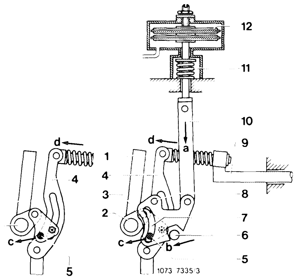
Since the control lever (4) is coupled with lever (3) by means of a pin, the control lever (4) and thereby control rod (9) will move in direction ‘‘d” so that less fuel will be injected. The more the adjusting lever (1) is adjusted in direction of idle (stop), the more will pin (5) of lever (3) move toward pivot point (8).
-OCOODNNDTAWN— Adjusting lever Adjusting lever shaft Lever Regulating lever Pin Stop Slotted lever Pivot Control rod 2 =o Pushrod Altitude box pretensioning 3 spring NO Diaphragm box =
As a result, adjustment during partial load will be in direction of less and will move to almost 0-adjustment in idling position. At low altitudes above normal altitude gate lever (7) will form a concentric circle around adjusting lever shaft (2), so that the governor procedure will not be corrected.
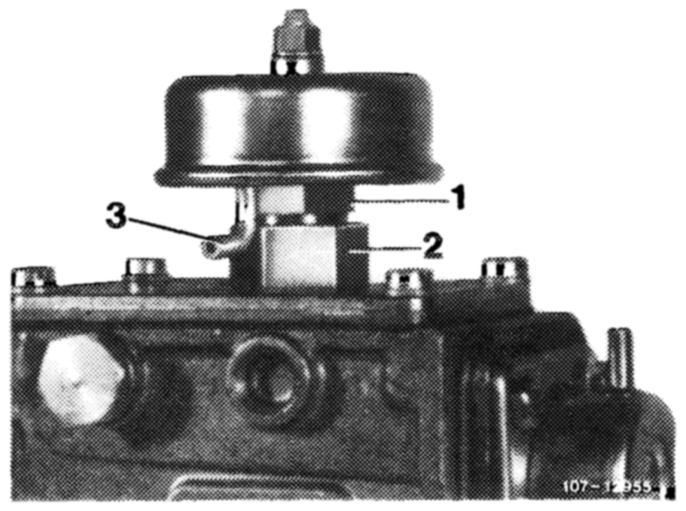
The upper governor cover on injection pump can no longer be screwed off, since the connecting rod in governor is mounted together with altitude adjusting box.
1 Apply counterhold to altitude adjusting box on hex head (1) and loosen coupling nut (2).
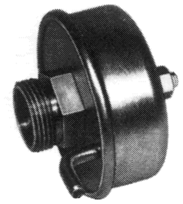
2 Unscrew altitude adjusting box. Use any washers remaining from removed altitude adjusting box, if required.
3 Mount new altitude adjusting box with washers. The venting pipe should be at the lowest point so that condensate, if any, can flow out.