Removal and installation of injection timer
WIS 07.1-240
Test values
End play of intermediate gear shaft 0.05–0.12
Tightening torques Nm
Hex nut for injection timer 70
Hex bolt for injection timer 40
Fastening screw for camshaft sprocket 80
Special tools
Impact puller for slide rail bolt (basic unit) – 116 589 20 33 00
Threaded bolt M 6, 50 mm long 116 589 01 3400
Threaded bolt M 6, 150 mm long poe aa – 116 589 02 34 00
Holder – 616 589 02 40 00
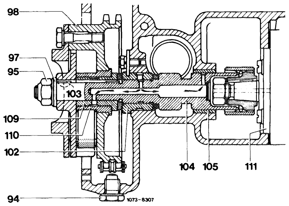
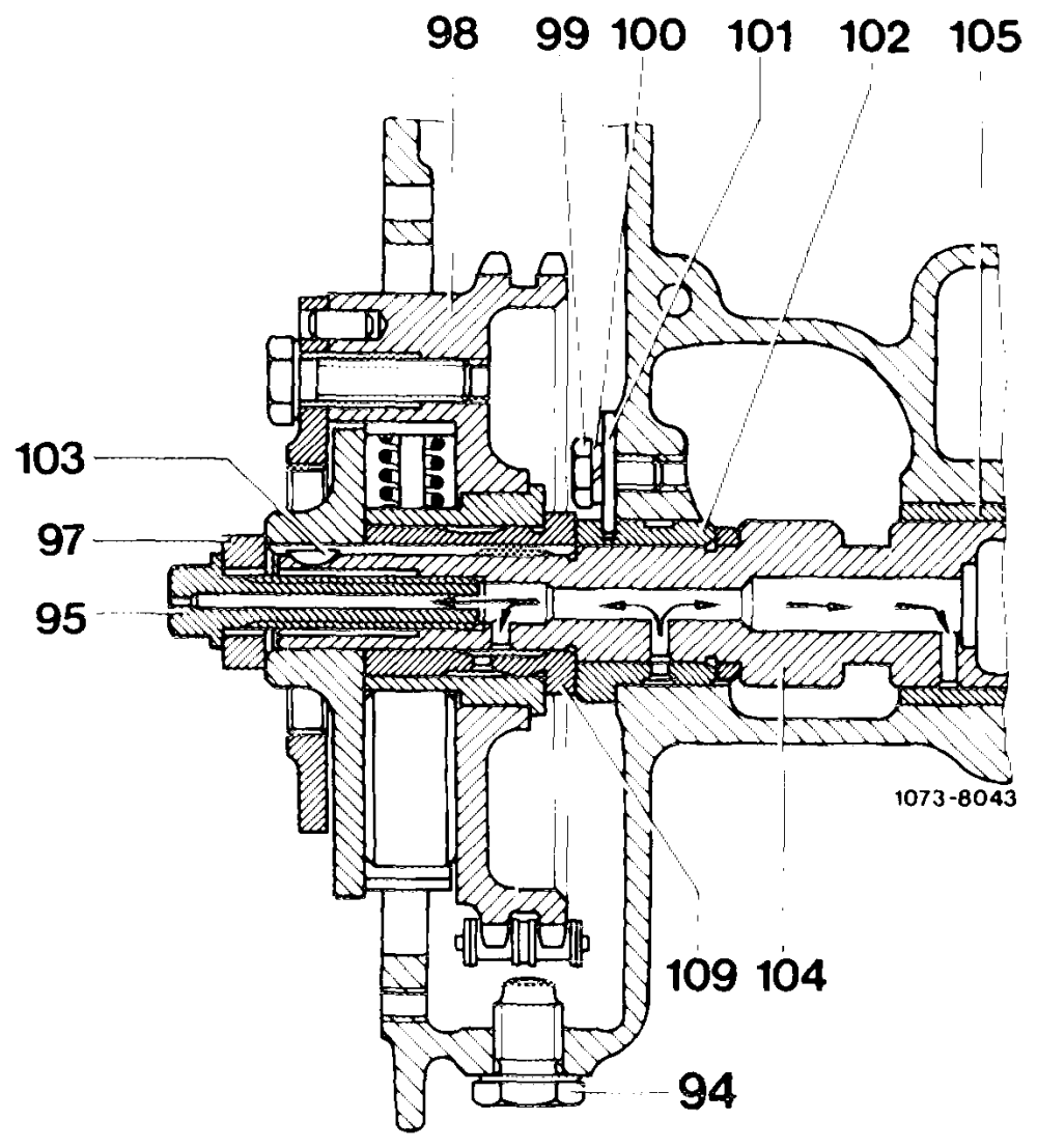
Fastening of injection timer changed.
1st version
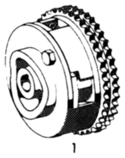
Injection timer is attached to intermediate gear shaft by means of a nut (95) and a ground washer (97).
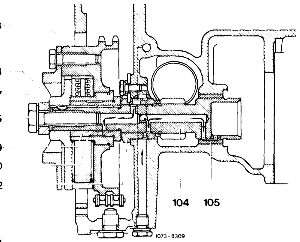
98 Injection timer is attached to intermediate gear shaft by means of a hex screw (95) M10 x 45. 103
97
95
109-
110
102
94
3rd version
Models 123.125 (sedan long) and 123.183 (T-sedan) with increased additional load are provided with a double diaphragm vacuum pump. The double diaphragm vacuum pump is driven via a toothed coupling sleeve, attachment and lubrication are by means of a hollow hex screw (95).
Attention! Do not mix up the different hex screws and injection timers.
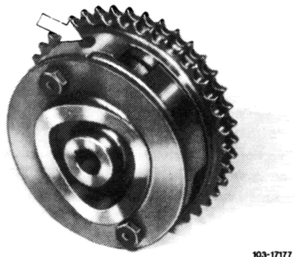
Adjusting range of injection timer changed from 6° to 7.5°.
A yellow dot outside on housing serves for identification.
This injection timer is also installed on engines 617.95 (turbodiesel).
On former engines with filament glow plugs the injection timer (7.5° adjusting range) may not be installed to prevent damage to glow plugs.
Removal
1 Remove radiator (20-420).
2 Unscrew suction and pressure line from vacuum pump and remove vacuum pump from cylinder crankcase.
3 Unscrew fastening nut or hex screw of injection timer.
4 Remove cylinder head cover.
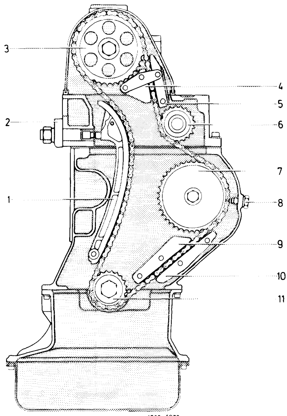
5 Unscrew fastening screw for camshaft sprocket (3).
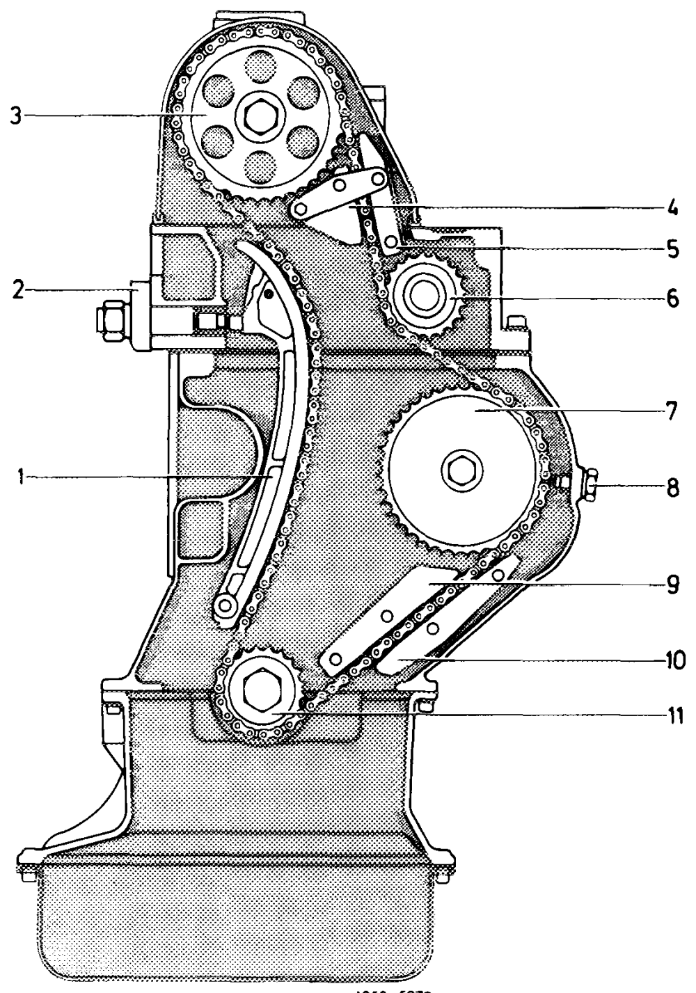
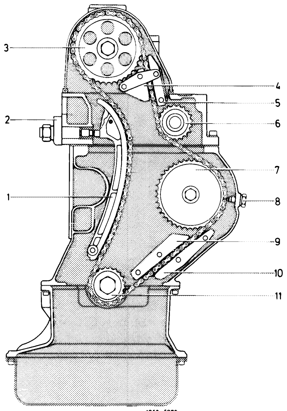
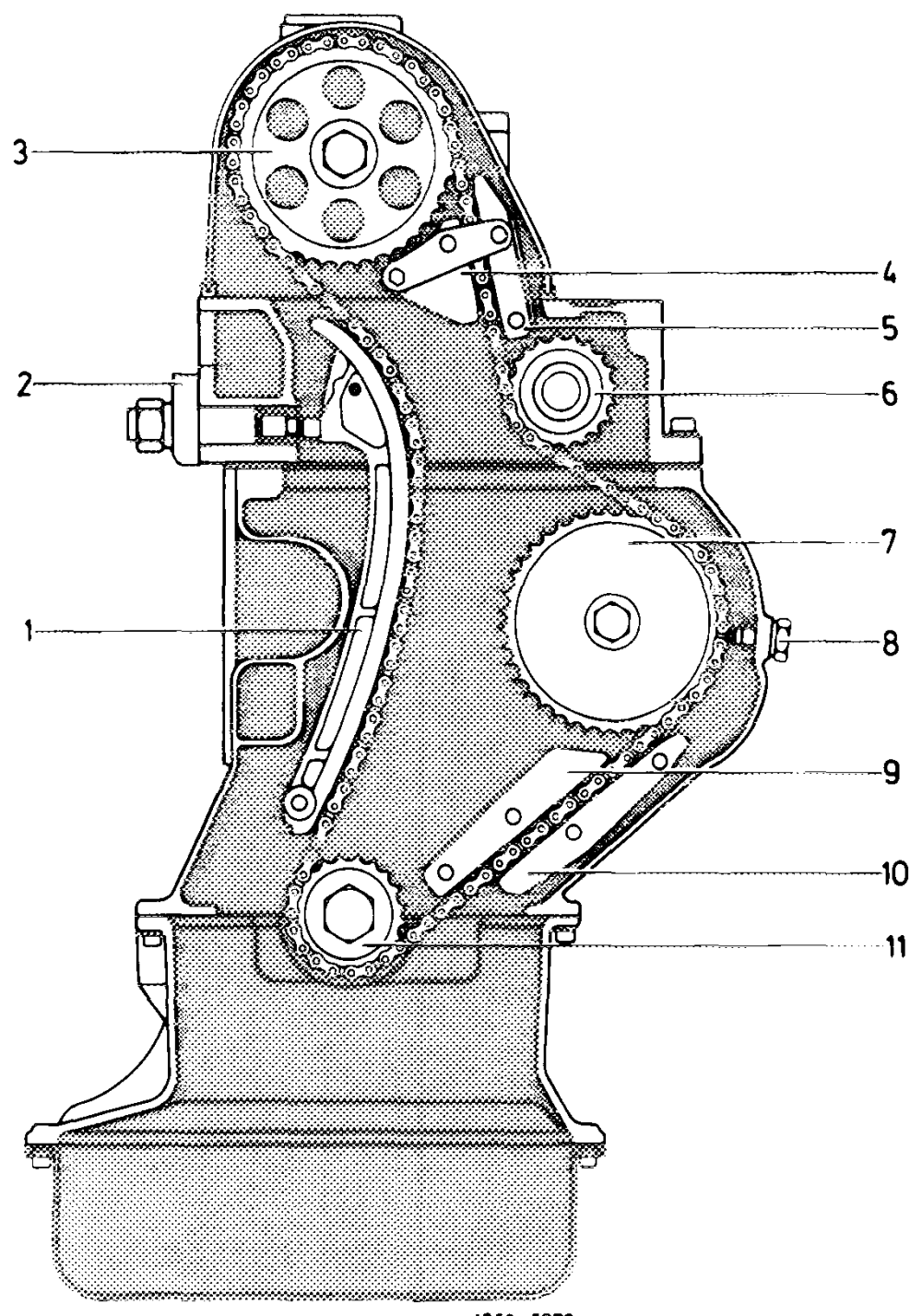
3 Camshaft sprocket 9 Slide rail 4 Shide rail 10 Slide rail 8 Lock screw
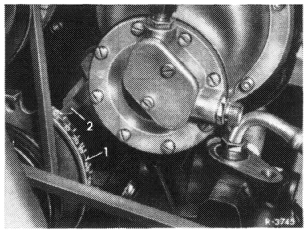
6 Rotate crankshaft in direction of rotation of engine to TOC mark.
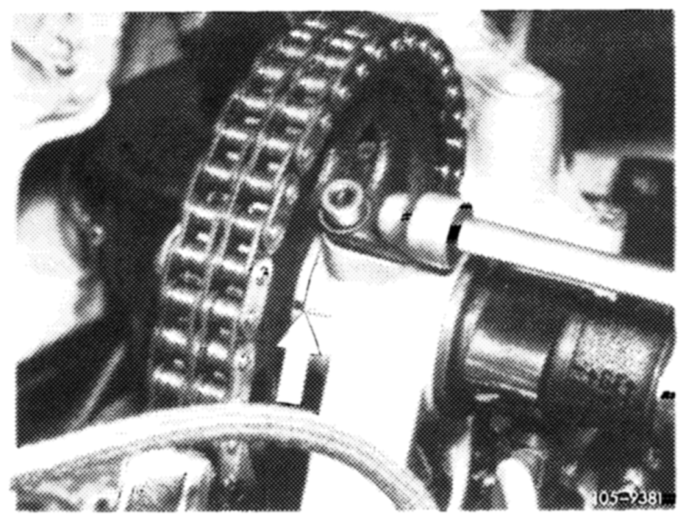
Camshaft must be in alignment with marking of compensating washer and 1st camshaft bearing (arrow).
and position of injection timer in relation to crankcase with paint.
8 Remove chain tensioner or push back pressure pin (05-310).
9 Remove slide rail (4) after removing hex screw.
10 Remove camshaft sprocket, while paying attention to compensating washer between camshaft and camshaft sprocket. Leave chain on camshaft and place together into chain box.
11 Unscrew lock screw (8) for chain drive and pull out upper bearing pin of slide rail (10) by means of puller.
3 Camshaft sprocket 9 Slide rail 4 Slide rail 10 Slide rail 8 Lock screw 1053~5973
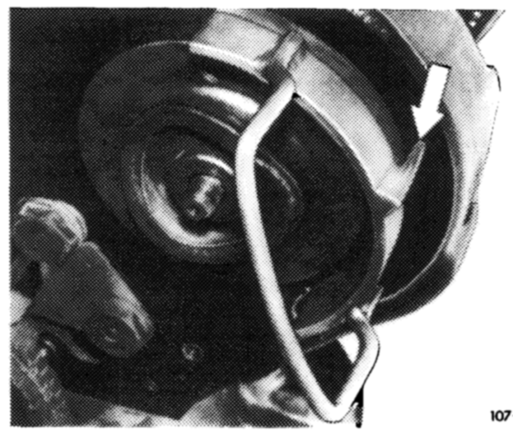
12 Lift chain from injection timer. For this purpose, slip holder in-between injection timer and chain. For better location, introduce guide pin (arrow) into threaded bore.
13. Remove or push off injection timer.
Attention! Do not rotate crankshaft and camshaft following removal of injection timer.
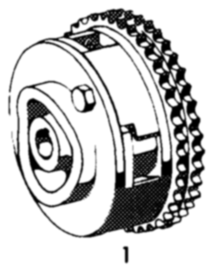
14 Remove bushing (2) for injection timer and thrust 5 o ring (3) from intermediate gear shaft. ~ “+H
3 : iY) 4 1074-6240
8 J 3 2
1 Injection timer 4 Intermediate gear shaft
2 Bushing 5 Woodruff key 3 > Thrust ring
replace, if required.
Installation
16 Lubricate thrust ring (3) and bushing (2) and slip on intermediate gear shaft. Pay attention to correct seat of both Woodruff keys (5) (Fig. item 14).
Note: If an injection timer must be replaced, place used injection timer on new injection timer in such a manner that the splines of both injection timers are in alignment. Then transfer painted mark on old injection timer on new injection timer.
17 Slip injection timer on intermediate gearshaft.
9 Slide rail 10 Slide rail
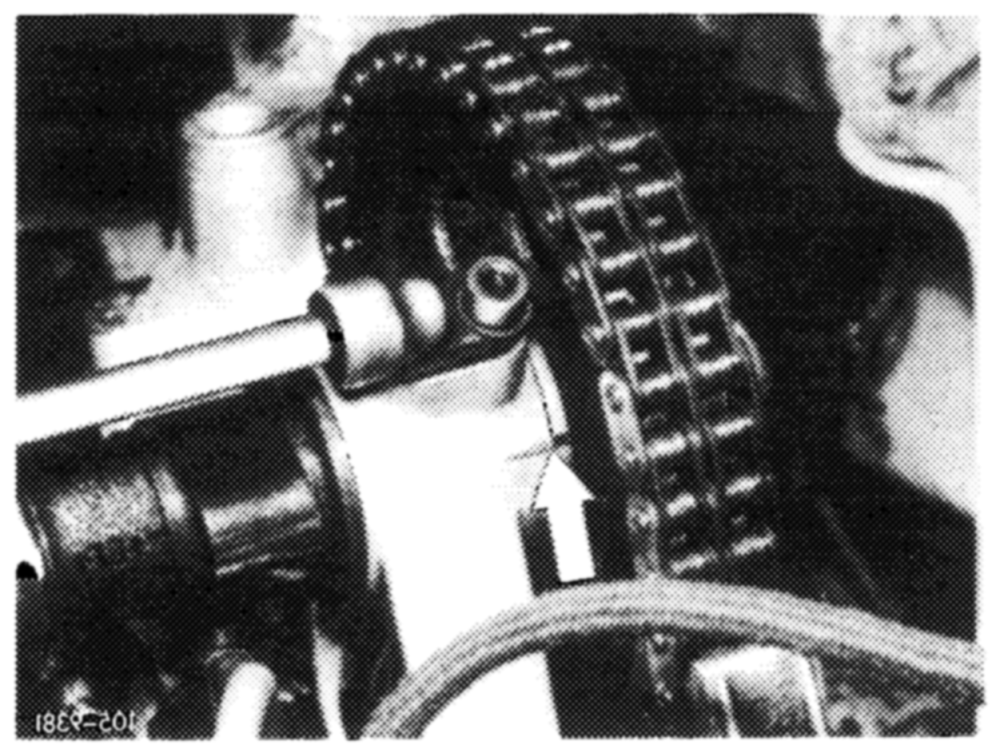
18 Pull chain in upward direction or lift camshaft sprocket with chain, making sure that the markings of injection timer and cylinder crankcase are in alignment. If required, rotate injection timer until the markings of injection timer and cylinder crankcase are in alignment. Then pull out holder.
19 Slip camshaft sprocket with chain mounted on camshaft, making sure that the marking of the compensating washer is in alignment with marking of first camshaft bearing.
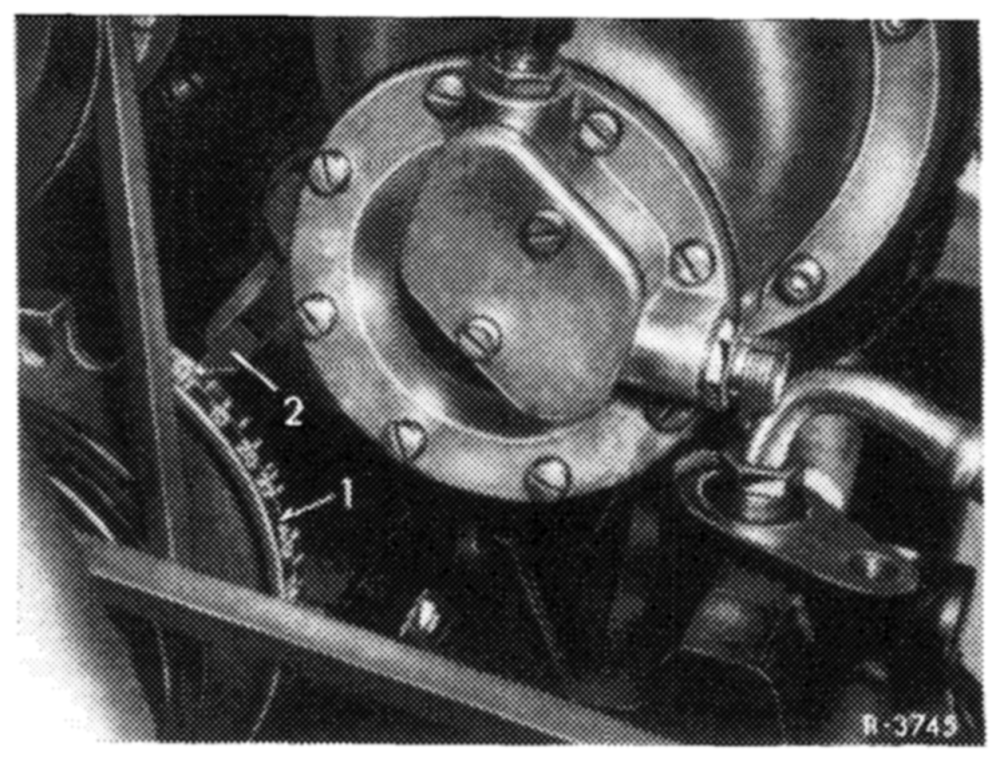
similar to removal and TDC position on balancing disc.
20 Install chain tensioner (05-310).
21. Introduce bearing pins of slide rail (10) into cylinder crankcase (Fig. item 5). Coat bearing pin at end with sealing compound. When knocking-in, make sure that the locking wire of the slide rail engages in notch of bearing pin.
22 Screw in lock screw (8) with new sealing ring and tighten (Fig. item 30).
23 Check begin of delivery and adjust, if required (07.1—110 and 115).
24 Vent injection system (07.1—140).
25 Mount hex nut and ground washer or hex screw.
Attention! Use only specified ground washer, part no. 615 990 03 40.
26 Check end play of intermediate gear shaft. Should be 0.05—0.12 mm, touch up thrust ring (3), if required.
x \
pose, turn hex nut or hex screw to the right up to stop by means of a wrench. Upon release, injection timer should return automatically to its old position.
29 Mount vacuum pump with new gasket and connect vacuum lines.
30 Introduce slide rail (4) with holder into bore of outer slide rail (5) and tighten.
CODAW Camshaft sprocket Slide rail Lock screw Slide rail Stide rail
31 Mount cylinder head cover, while paying attention to correct seat of rubber gasket.
32 Mount regulating linkage, check and adjust, if required (30—300).
33 Install radiator and connect all lines.
34 Run engine and check for leaks.