Checking and adjusting camshaft timing
WIS 05-215
Timing with 2 mm valve lift
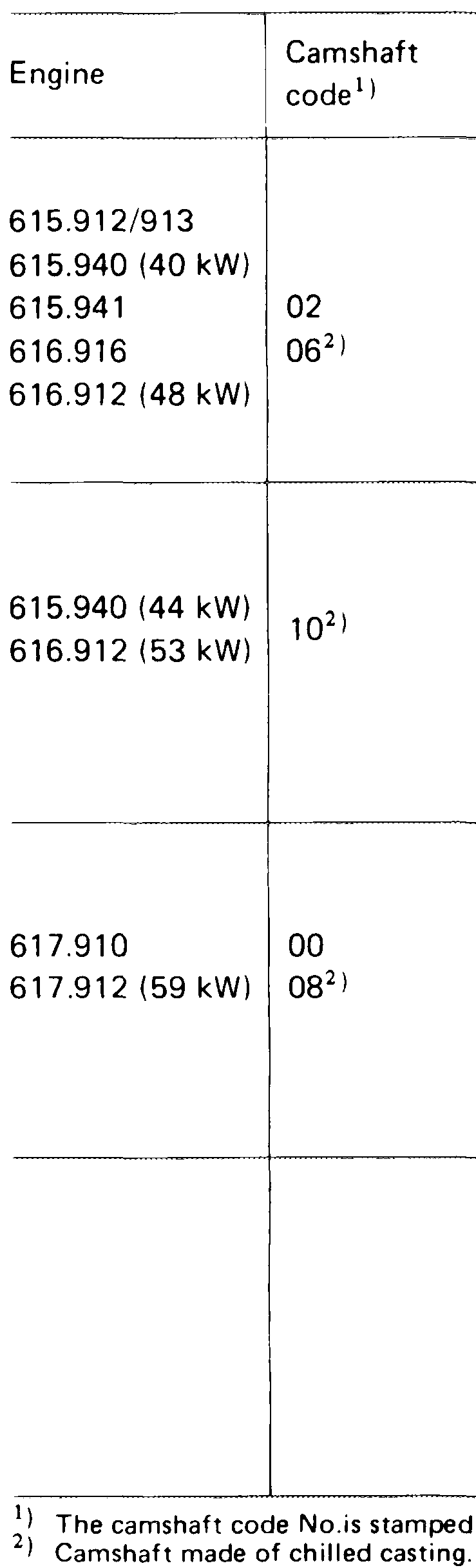
| Intake valve opens after TDC | closes after BDC opens before BDC closes | Exhaust valve | ||
| with new timing chain | ||||
| 11.5° with used timing chain (from about 20,000 km) | 13.5° | 21° | ||
| 13.5° | 15.5° | 19° | ||
| with new timing chain | ||||
| 9° | 15° | 27° | ||
| chain with used timing | (from about 20,000 | km) | ||
| 11° | 17° | 25° | ||
| with new timing chain 11.5° | 13.5° | 21° | ||
| with used timing chain (f;om about 20,000 km) | ||||
| 13.5° | 15.5° | 19° | ||
| with new timing chain | ||||
| with used timing chain (from about 20,000 km) | ||||
| clearance | in the aft camshaft end. | engine cold (approx. 20 °C) 0.10?) | engine hot (60 °C + 15 0.15!) | |
Exhaust 0.30 0.35
1) 09.05 mm greater for steady ambient temperatures below —20 °C.
Tightening torques Nm (kpm)
Bolts for cylinder head cover (2ngine 615) 5 (0.5) Nuts for cylinder head cover (engines 615, 616, 617) 15 (1.5)
Waisted bolt for camshaft sprocket 80 (8)
Special tools
Valve adjusting wrench 14 mm (two) – 615 589 00 01 00
Holding wrench for valve spring cap – 615 589 00 03 00
Socket 27 mm, 1/2’ drive to op . _(s crank engine oer 89) – 001 589 65 09 00
ert a Dial gauge holder LO – 121 589 00 21 00
fo” Impact extractor for bearing pin (basic unit) ye – 116 589 20 33 00
Threaded stud for impact extractor aay 116 589 01 3400 M 6, 50 mm long 1004-6368
Box-end wrench 20.8 mm for glow plugs – 617 589 00 03 00
Commercially available tool
e.g. Mahr, 7300 Esslingen Dial gauge A 1 DIN 878 order No. 810 i 7
Note
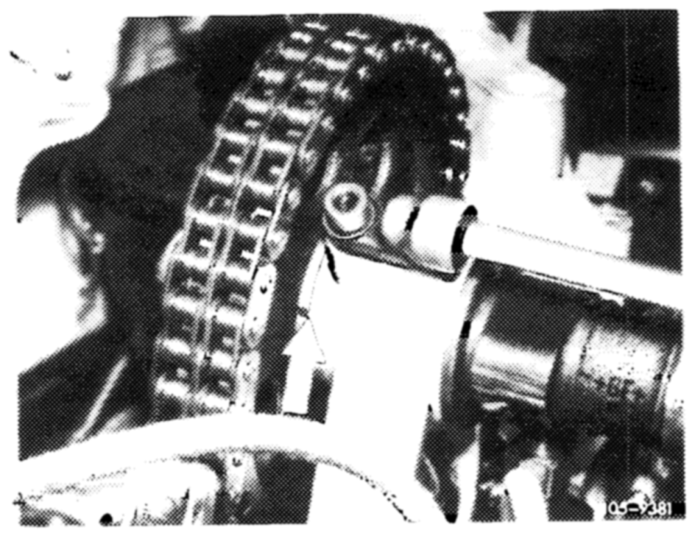
For assembly operations it is sufficient when marks (arrow) agree at TDC position of No. 1 cylinder.
In special cases, e.g. complaints about poor performance, it is necessary to check and adjust as follows the opening angle at the intake valve of No. 1 cylinder.
Timing is to be measured with 2 mm valve lift, valve clearance being cancelled for this purpose.
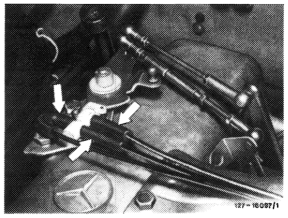
1 Remove cylinder head cover.
On vehicles with automatic transmissions and vacuumcontrolled modulating pressure, additionally disconnect vacuum lines at switch-over valve.
Caution: Be sure not to cross vacuum lines. The pipe unions and vacuum lines are color coded.
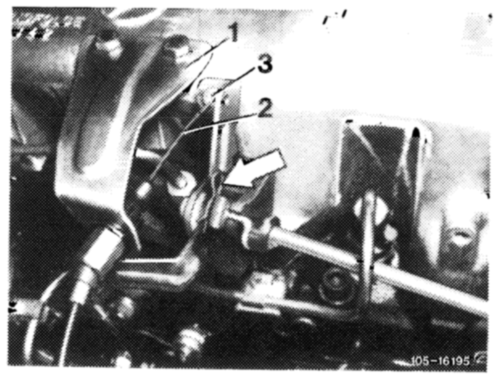
On engines with longitudinal control spindles, detach all control rods. Withdraw retainer (arrow) and force longitudinal control spindle in aft direction. Unscrew bracket (1) and unclip idle control cable (2) with plastic sleeve (3).
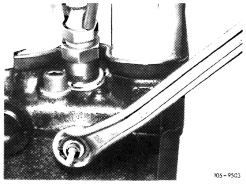
2 Unscrew glow plugs using 20.8 mm box wrench.
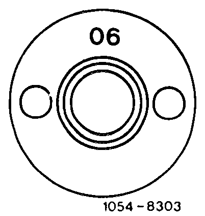
3 Note camshaft code, stamped in aft camshaft end.
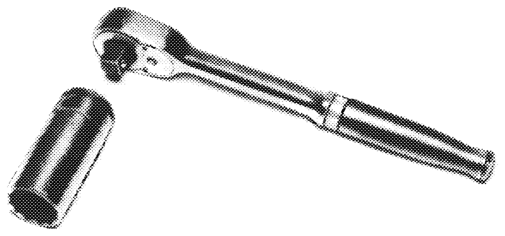
4 Using tool combination, turn crankshaft until cam peak is pointing upward.
Caution: Engine must not be cranked at fastening bolt of camshaft sprocket. While conducting measurement be sure not to turn engine backward because highly incorrect readings will otherwise be obtained.
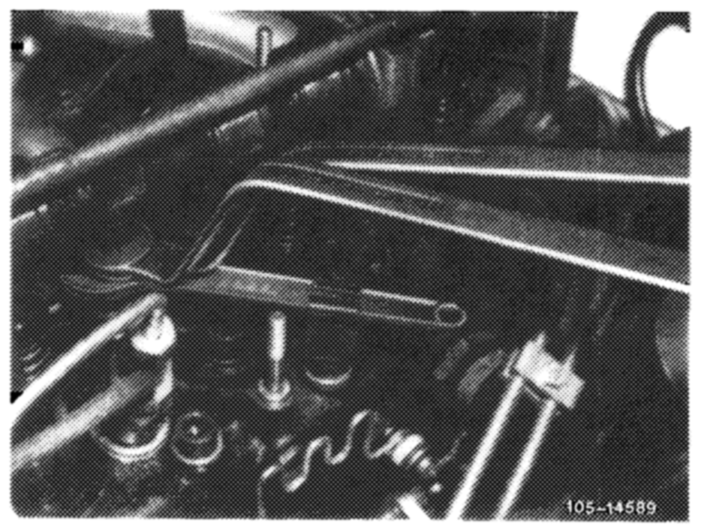
R 100/6498
5 Screw cap nut upward at intake valve of No. 1 cylinder until valve clearance is just cancelled (05—210).
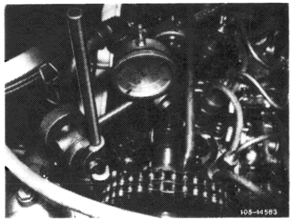
6 Using threaded sleeve, attach dial gauge holder to stud at front right, and to strap for cylinder head cover.
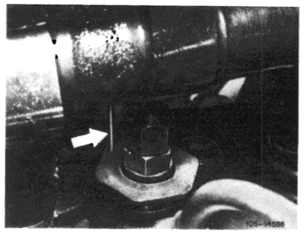
7 Insert dial gauge and fasten so that contact button rests on valve spring cap (arrow) with less than 3 mm preloading (small dial gauge pointer).
Turn gauge dial until large pointer is on ‘‘0’’.
Caution: Dial gauge contact button must be exactly perpendicular to valve spring cap.
direction until small dial gauge pointer has dropped by 2 mm (valve lift) to 1 mm.
At this position, the reading on the balance plate must agree with the specification ‘Intake valve opens”.
Adjust-nent
If a timing correction is required it will be necessary to use an offset Woodruff key, or to fit a new timing chain if the old one is stretched too much.
Woodruff keys are available in following steps:
Offset Part No. For correction of mm about
0.7 621 991 04 67 4° kW 0.9 621 991 02 67 61/2° kW
11 621 991 01 67 8° kW 1.3 621 991 00 67 10° kW
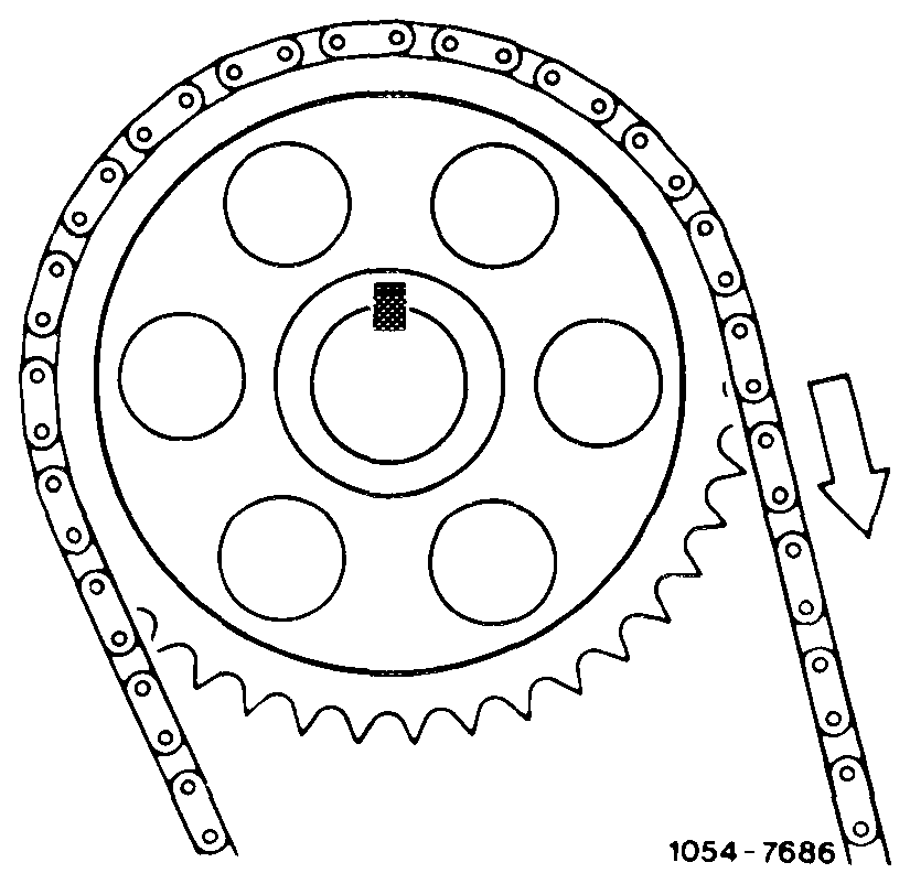
An offset of one tooth on camshaft sprocket gives a correction of about 18° at crankshaft.
Setting the Woodruff key off to right (straight-ahead A) advances opening angle, and setting off to left (B) retards opening angle.
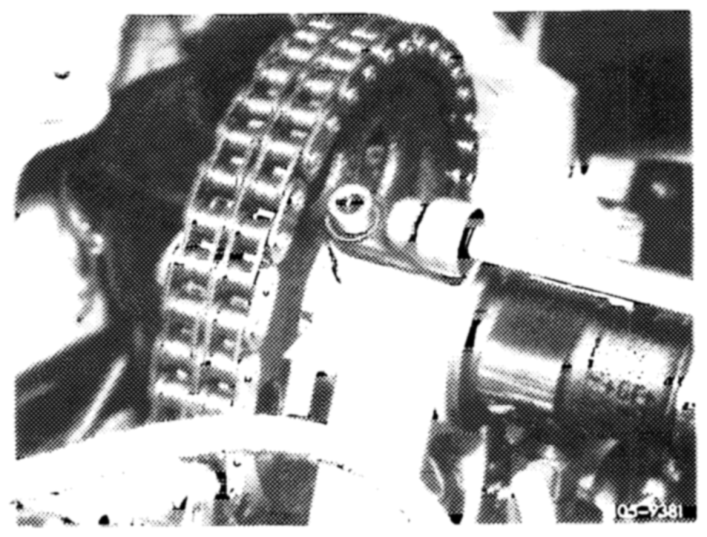
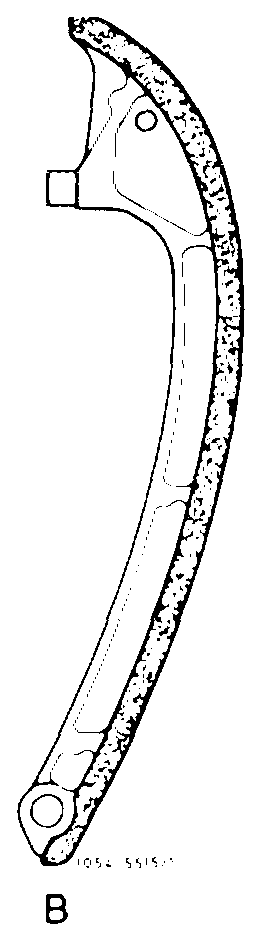
10 On engines with tension rail version (A) remove chain tensioner (05—310).
On engines with lightweight tension rail (B) slacken thrust pin of chain tensioner.
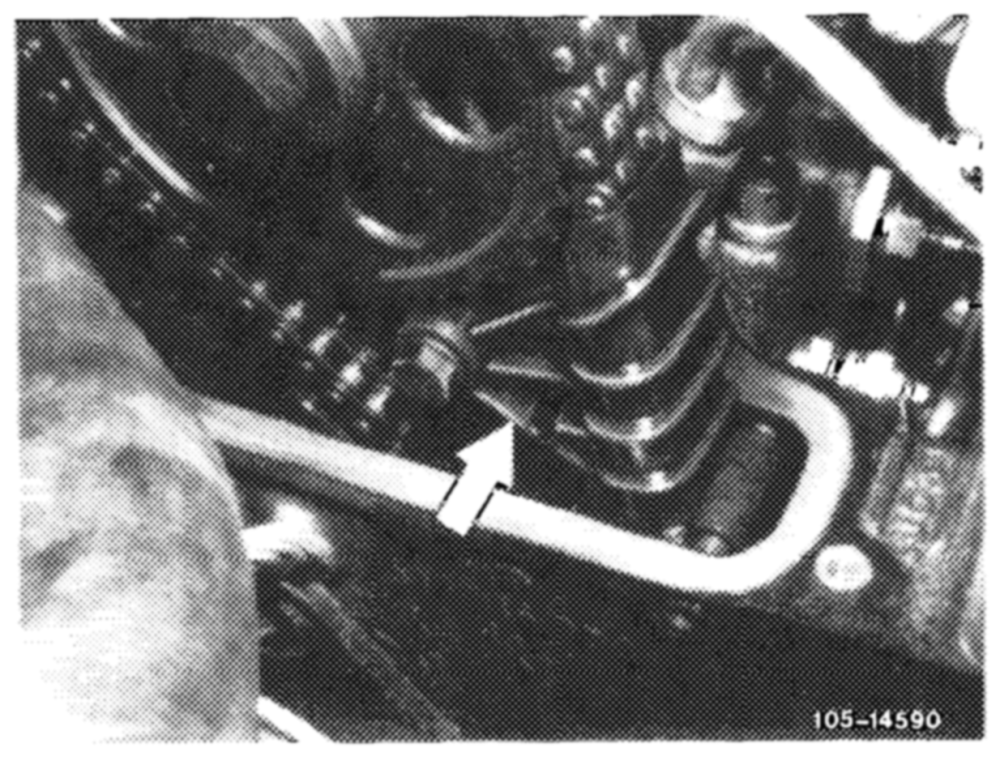
11 Remove slide rail from cylinder head. Withdraw bearing pin, using impact extractor.
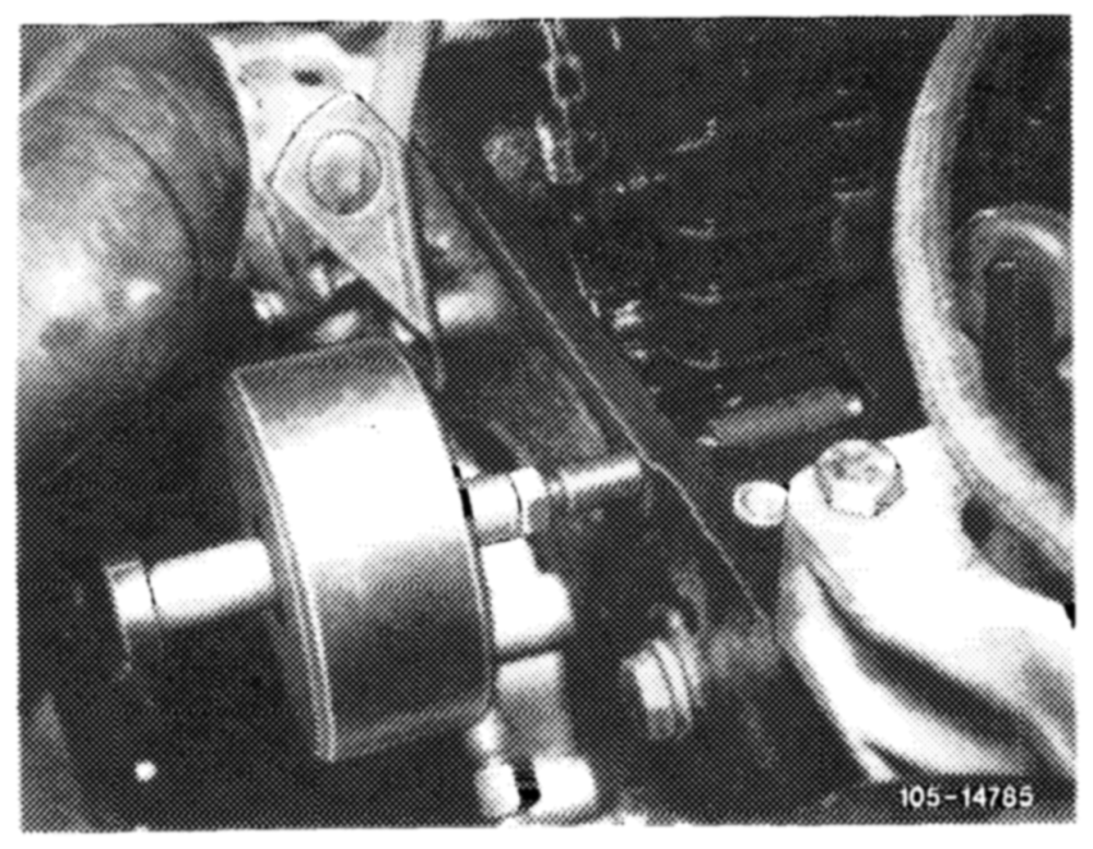
On vehicles with level control, additionally remove delivery oil pump togeth2r with connected lines, depositing on one side.
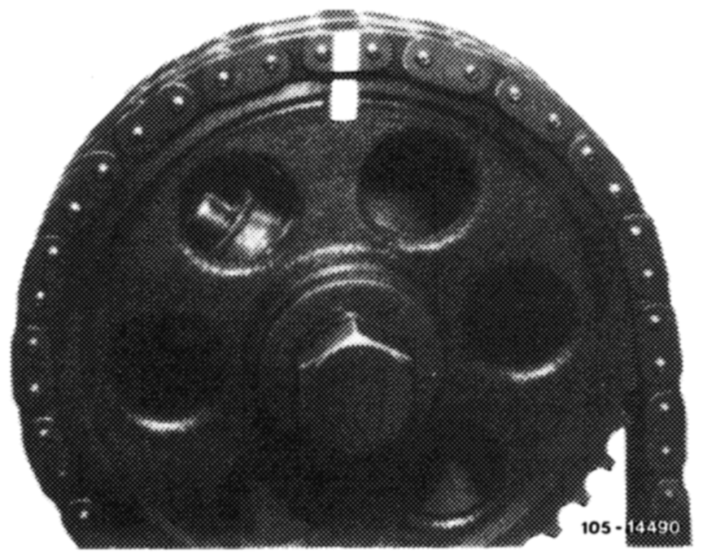
chain to show how they fit together.
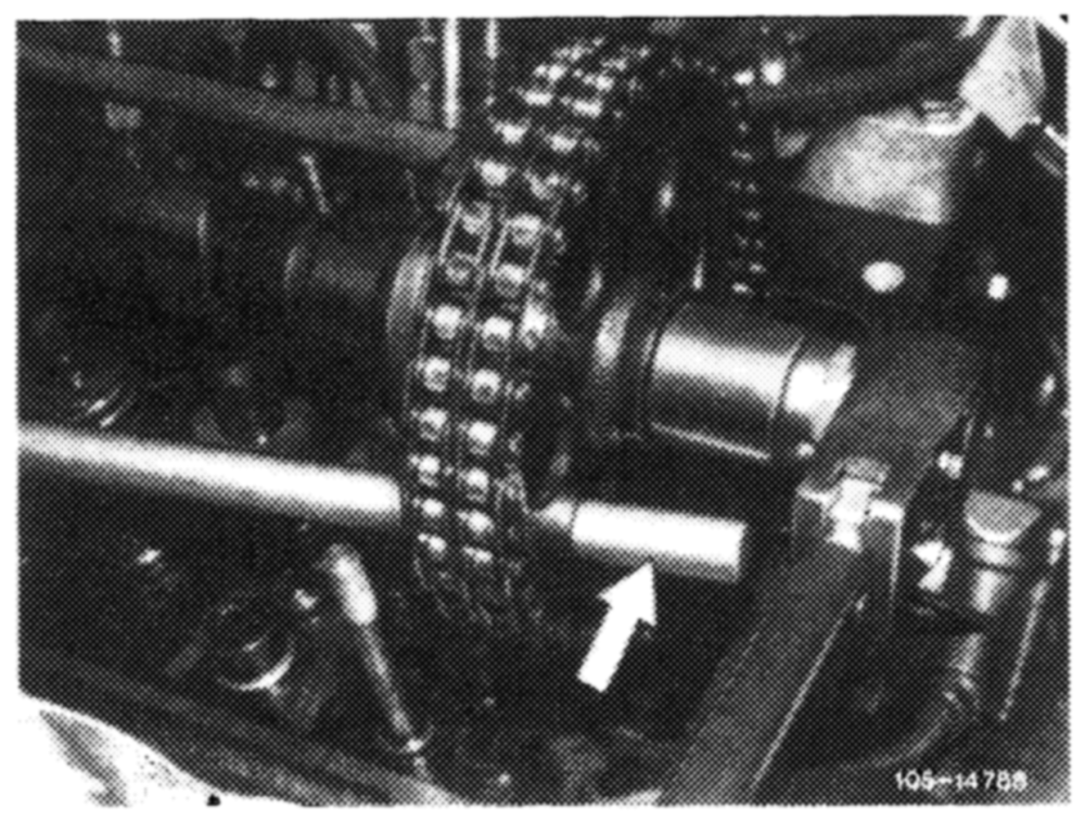
13. Remove camshaft sprocket.
To release waisted bolt secure camshaft sprocket with .
screwdriver or steel pin.
14 Place cloth beneath camshaft and remove Woodruff key.
15 Insert selected Woodruff key.
16 Fit camshaft sprocket, noting color coding.
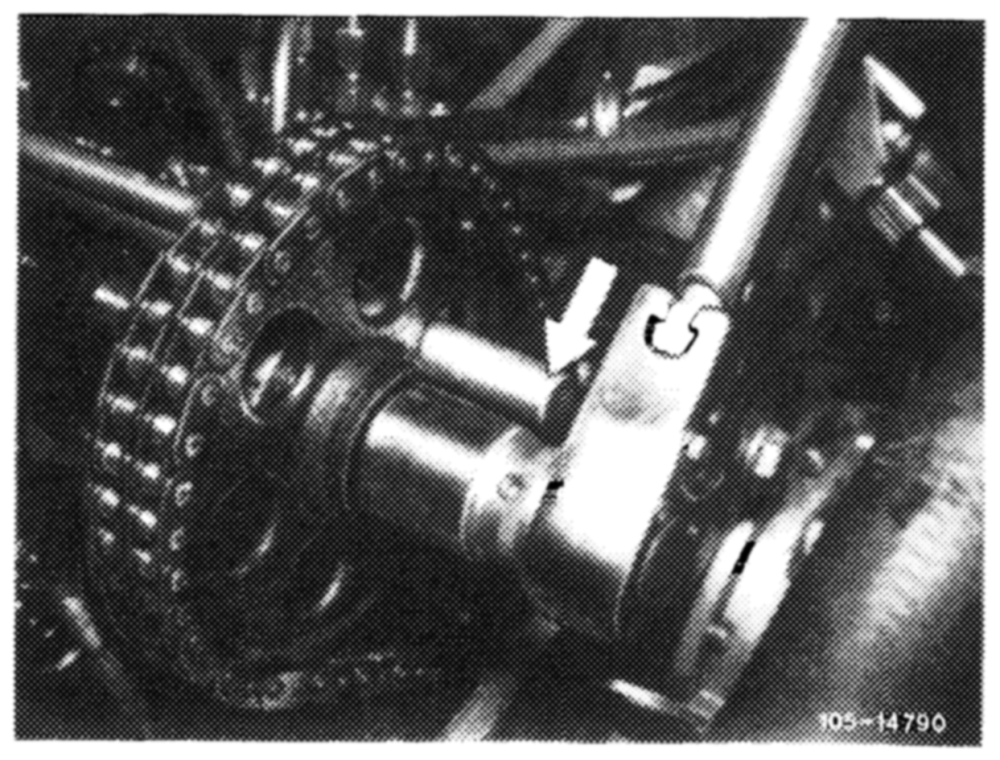
Do not tighten waisted bolt.
17 Repeat jobs No. 7 and No. 8.
18 Torque waisted bolt of camshaft sprocket to 80 Nm (8 kpm), securing sprocket with screwdriver or steel pin for this purpose.
19 Fit slide rail.
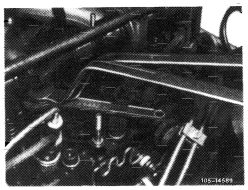
22 Adjust valve clearance at intake valve of No. 1 cylinder (05-210).
23 Attach delivery oi! pump-of level control system.
24 Insert and connect glow plugs.
25 Fit cylinder head cover.