Checking preglow system
WIS 15-510
Conventional tools
Voltmeter (measuring range O—3 volts/O—16 volts)
Ammeter (measuring range O—60 amps)
Note Battery charged min 60 % (acid density approx. 1.22 g/cc).
A. With glow plug resistance control engine 615, 616 in model 115.1
a) Preglow system not preglowing
This complaint indicates an interruption in circuit of preglow system.
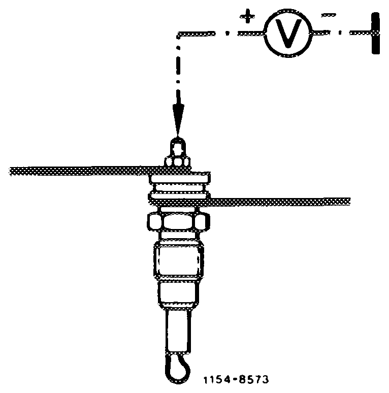
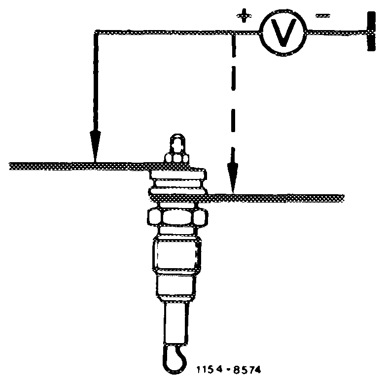
Set voltmeter to measuring range 0–16 volts. Connect plus cable of voltmeter to input (threaded stud) of glow plug of 4th cylinder and minus cable to ground. Actuate preglow system and read voltage on voltmeter.
If voltmeter indicates 12 volts, the interruption is located at glow plugs or their connections.
If the voltmeter indicates 0 volt, look for interruption at preglow starter switch or on glow plug resistance control.
1. Checking glow plugs for interruption
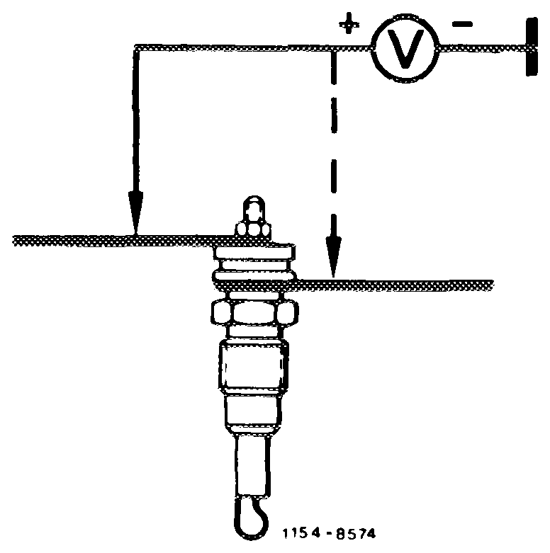
Connect minus cable of voltmeter to ground. Check voltage at current input and output of the 4 glow plugs by means of plus cable of voltmeter.
If a glow plug at current input shows 12 volts and at output 0 volt, the respective glow plug is interrupted and must be exchanged.
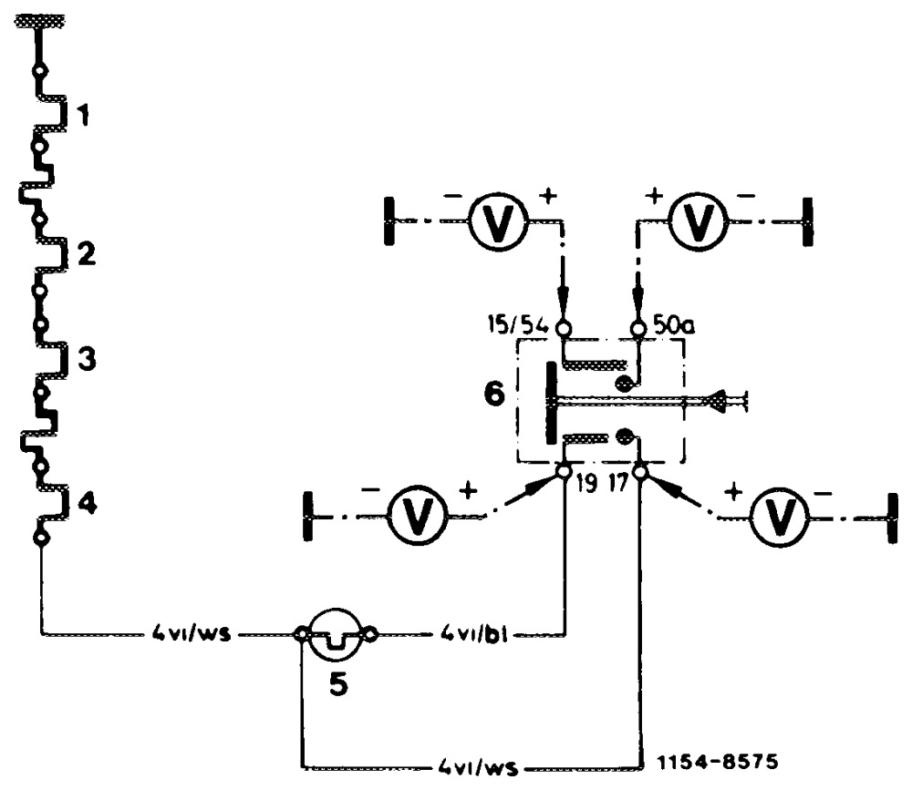
resistance control
Connect minus cable of voltmeter to ground. By means of the voltmeter plus cable the connections of the preglow starter switch should indicate the following values:
In switch position 0 (key in steering lock in position “2″) on terminal 15/54 = 12 volts.
In switch position (preglow position) on terminal 19 = approx. 11 volts.
Preglow starter switch
In switch position II (starting position) on terminal 17 and on terminal 50a = approx. 11 volts.
If the voltage on terminal 15/54 = 0, check line to steering lock switch or steering lock switch as well as connection.
If the voltage on terminal 19, 17 or 50a = O, exchange preglow starter switch.
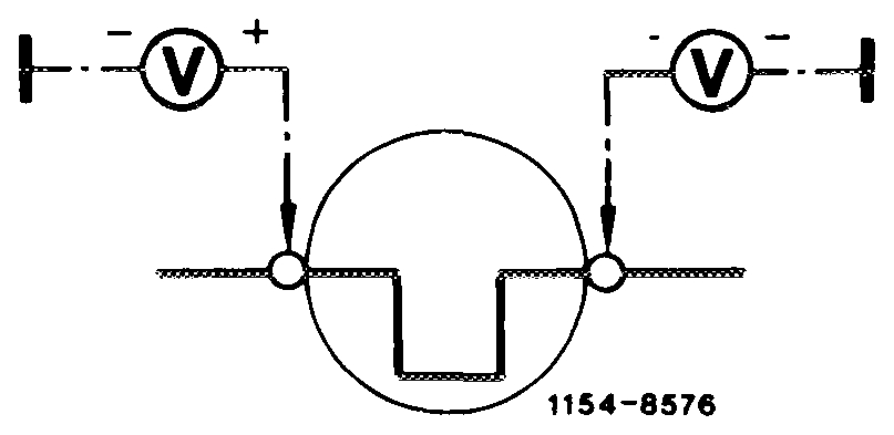
Glow plug resistance control
Voltage at glow plug resistance control input and output approx. 11 volts.
If voltage is 0, the line or the glow plug resistance control is interrupted and line or control must be replaced.
b) Preglow system glows too slowly or too fast —® A,
In the event of such a complaint, the current flowing through the preglow system is too low as a result of transfer resistances or too high as a result of a short-circuit.
First measure glow current with ammeter.
For this purpose, connect ammeter at connection of glow plug cylinder 4.
Glow current in preglow position: approx. 50–55 amps.
15.4-510/2. F2
Measured after 15 seconds (battery charged min 60 %).
If this glow current is not attained, measure voltage drop in preglow system by means of voltmeter.
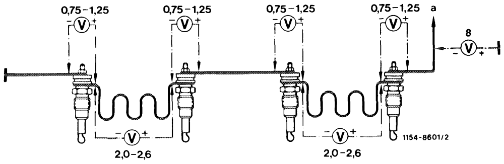
Check connections for tight seat.
a To glow plug position control
If this glow current is exceeded, a short-circuit in preglow system is indicated (glow plugs, preglow starter switch, preglow resistance control).
If a glow plug fails as a result of a short-circuit, measure glow current once again after replacing glow plug.
B. With preglow indicator lamp engine 615, 616 in model 123.1
a) Preglow system not preglowing
This complaint is based on an interruption in current circuit of preglow system.
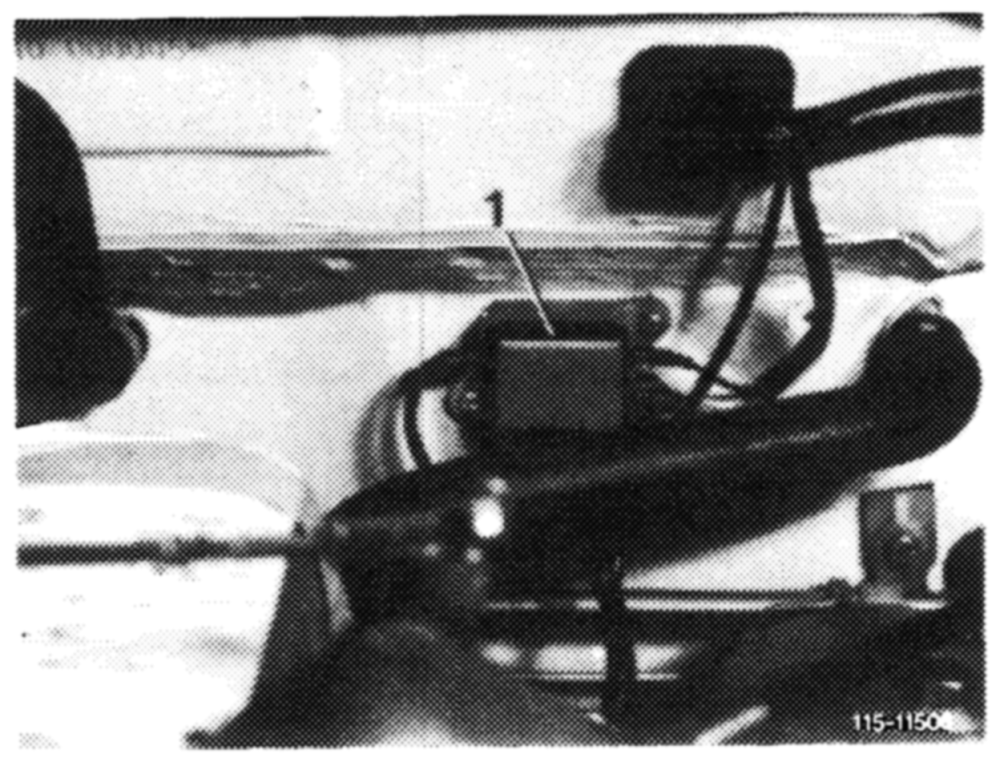
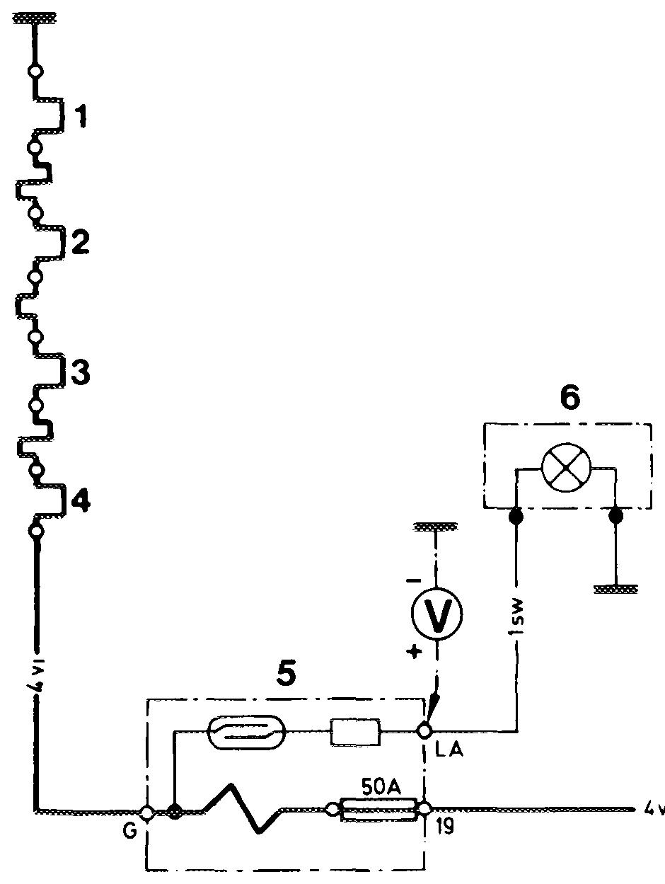
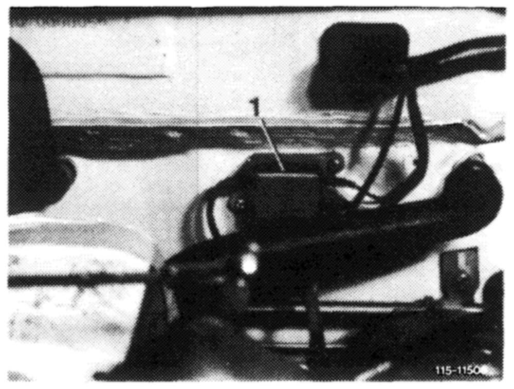
Attention! The preglow system is fused, check fuse. (The separate fuse box is mounted on front wail inside engine compartment).
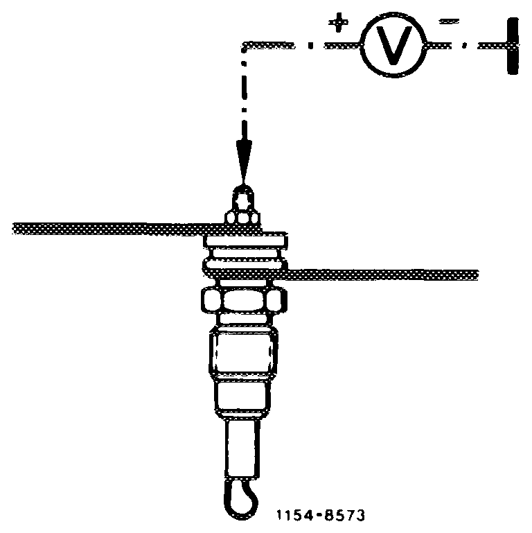
Connect plus cable of voltmeter to input (threaded stud) of glow plug of 4th cylinder and minus cable of voltmeter to ground. Actuate preglow system and read voltage on voltmeter.
If voltmeter indicates 12 volts, the interruption is at glow plugs or their connections.
If voltmeter indicates O volt, the interruption is at preglow starter switch or its connections.
1. Checking glow plugs for interruption
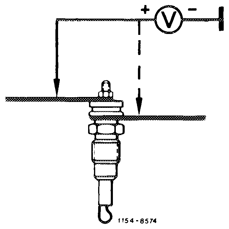
Connect minus cable of voltmeter to ground. Check voltage at current input and output of the four glow plugs by means of plus cable. If 12 volts are measured at input of a glow plug and 0 volt at output, the respective glow plug is interrupted and must be replaced.
2. Checking preglow starter switch and connections
Connect minus cable of voltmeter to ground. The following values must be measured at connections of preglow starter switch with plus cable of voltmeter:
In switch position 0 (key in steering lock in position ‘’2’’) on terminal 15/54 = 12 volts.
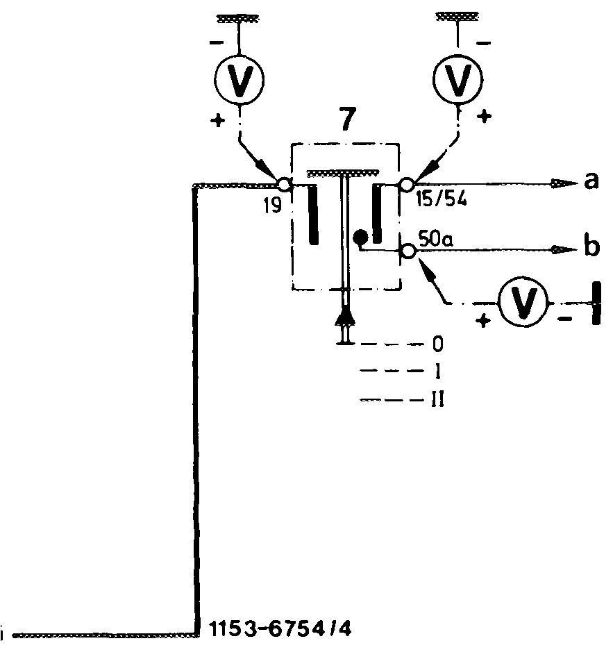
In switch position and I! (preglow or start position) on terminal 19 and 50a = approx. 11 volts.
line to steering lock switch or steering lock switch itself, as well as the respective connection.
If the voltage at terminal 19 and 50a = 0 volt, replace preglow starter switch.
b) Preglow system preglowing too slowly or too fast
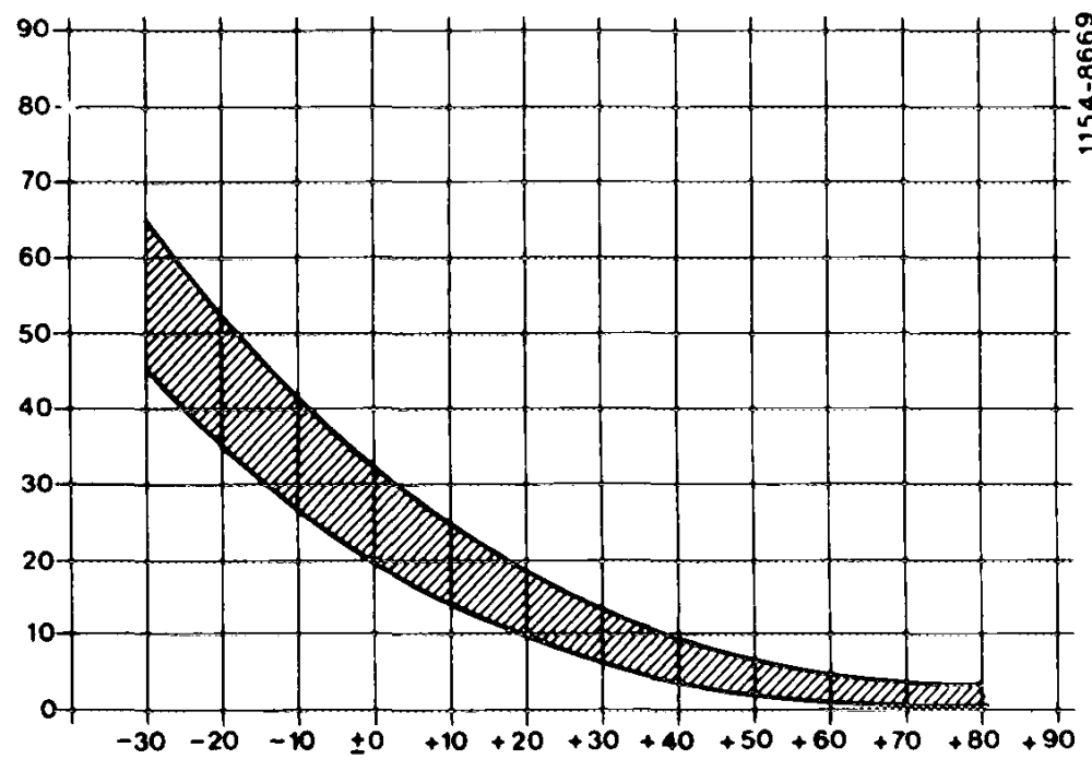
Nominal time at: +20 °C approx. 12 seconds — 5 °C approx. 30 seconds Times
Temperature °C Glow period at 52 amps
In the event of this complaint, the current flowing through preglow system is too low as a result of transfer resistances, or too high as a result of a short-circuit.
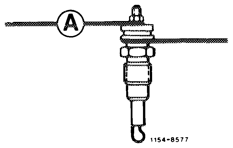
First, measure glow current with ammeter.
For this purpose, connect ammeter at glow plug connection of cylinder 4.
Glow current in preglow position: approx. 50–55 amps.
Measured after 15 seconds (battery charged min 60 %).
If this glow current is not attained, measure voltage drop in preglow system with voltmeter.
Check connections for tight seat.
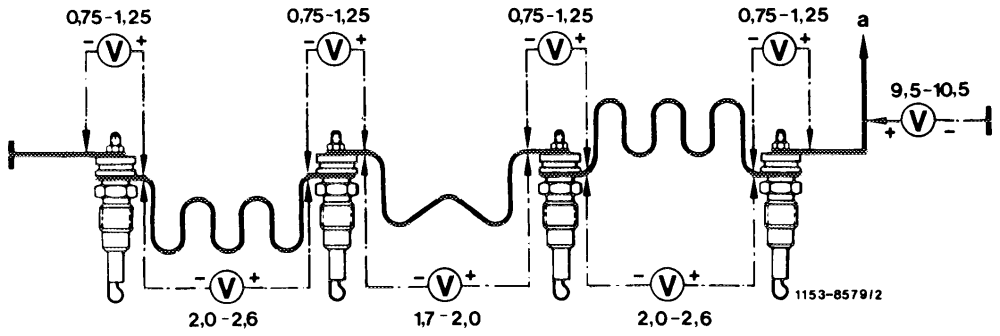
a To fuse
If this glow current is exceeded, a short-circuit in preglow system is indicated (glow plugs, preglow starter switch).
If a glow plug is lost as the result of a short-circuit, exchange plug and measure glow current once again.
c) Preglow system glows, but preglow indicator lamp not indicating
Connect voltmeter to connection LA of fuse box (5) and to ground. Actuate preglow system and read voltage on voltmeter.
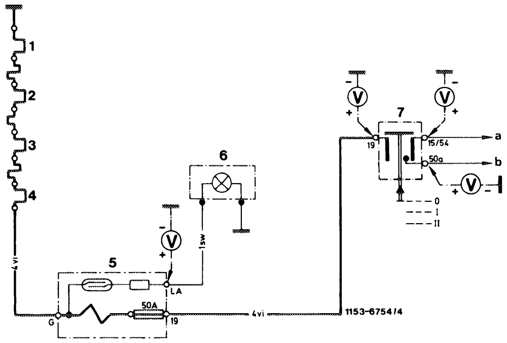
If voltage indicates approx. 12 volts, check bulb and feed lines of preglow indicator lamp (pay attention to tight seat of bulb in socket).
current.
\f approx. 50–55 amps are measured, the reed contact of the fuse box is defective and the fuse box must be replaced.
!f a low glow current is measured, a transfer resistance in preglow system is indicated or the battery is insufficiently charged.
Check connections of glow plugs for tight seat and recharge battery, if required.
C. With ready-for-starting lamp engine 615, 616 in model 123.1
a) Preglow system not preglowing
This complaint is based on an interruption in current circuit of preglow system.
Attention! Preglow system is fused. Check fuse. (The separate fuse box is mounted on front wall of engine compartment).
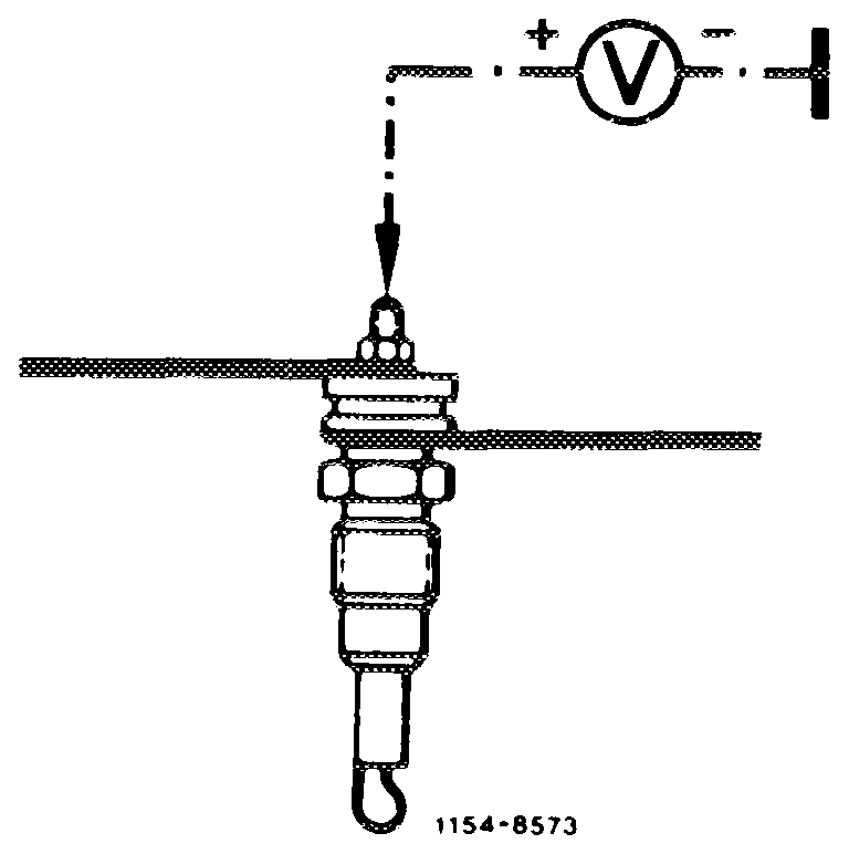
Set voltmeter to measuring range O—16 volts. Connect plus cable of voltmeter to input of glow plug of 4th cylinder and connect minus cable to ground. Operate preglow system and read voltage on voltmeter.
If voltmeter indicates 12 volts, look for fault on glow plugs or their connections.
{f voltmeter indicates 0 volt, look for fault on preglow starter switch or its connections.
1. Check glow plugs for interruption
Connect minus cable of voltmeter to ground. Check voltage with plus cable of voltmeter at current input and current output of the four glow plugs.
If 12 volts are measured at current input of a glow plug and 0 volt at output, this glow plug is interrupted and must be replaced.
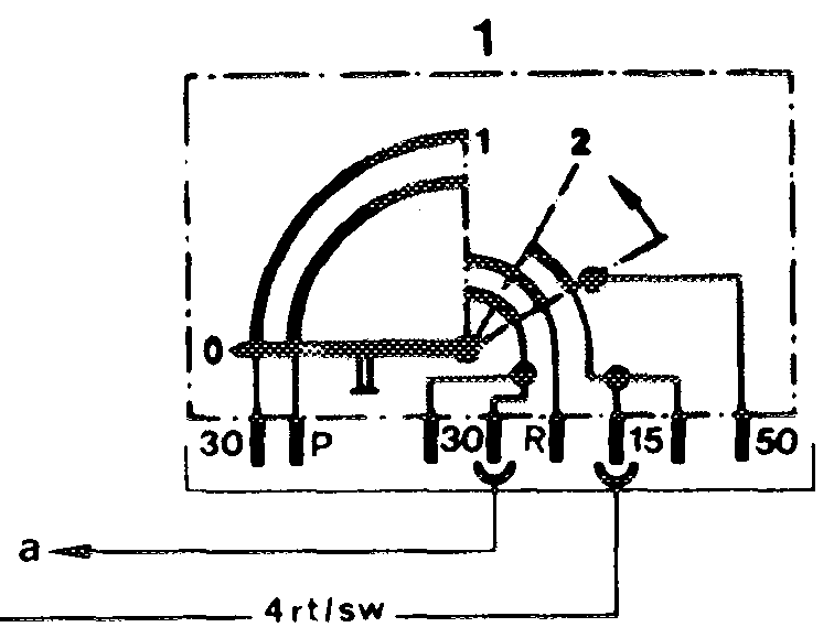
Connect minus cable of voltmeter to ground. Measure the following values with plus cable of voltmeter at connections of preglow starter switch:
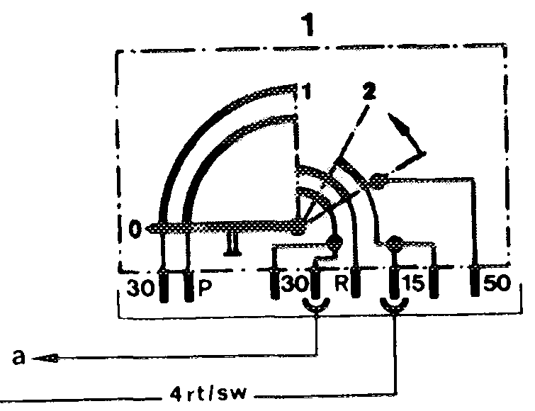
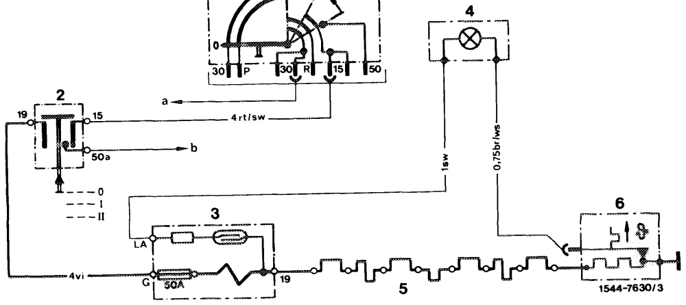
In starter position O (key in steering lock in Position ‘’2”) on terminal 15 = 12 volts.
If voltage at terminal 15 = 0 volt, check line to steering lock switch or steering lock switch itself as well as the respective connection.
Voltage in switch position and II on terminal 19 and 50a = approx. 11 volts.
If voltage on terminal 19 and 50a = 0 volt, replace preglow starter switch.
b) Preglow system preglows too slow or too fast
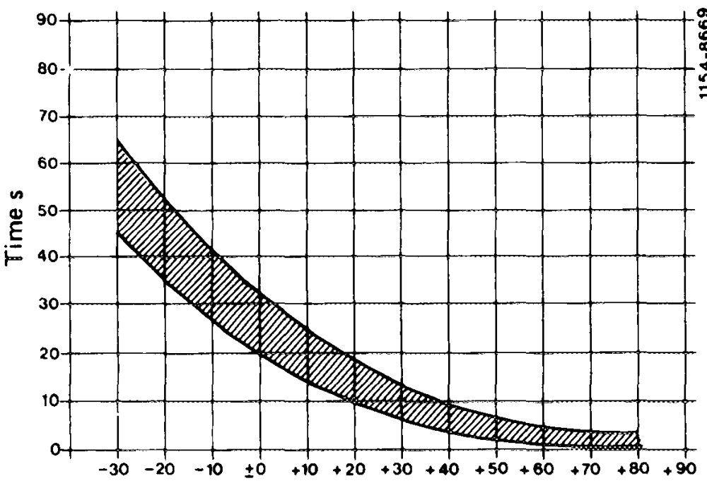
Nominal time at: +20 °C approx. 12 seconds — 5 °C approx. 30 seconds
Temperature °C Glow period at 52 amps transfer resistances, or too much current as the result of a short-circuit.
Measure glow current first with ammeter.
For this purpose, connect ammeter to connection of glow plug for cylinder 4.
Glow current in preglow position: approx. 50–55 amps.
Measured after 15 seconds (battery charged at least 60 %).
If this glow current is not attained, measure voltage drop in preglow system with voltmeter.
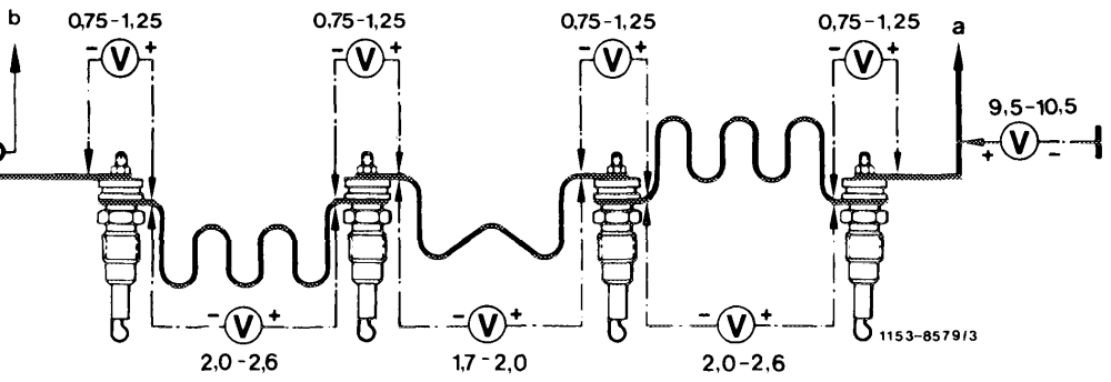
Check connections for tight seat.
cr
–
a_ To fuse b_ To preglow indicator lamp
If this glow current is exceeded, a short-circuit in preglow system is indicated (glow plugs, preglow starter switch).
If a glow plug is lost by a short-circuit, measure glow current once again after replacing plug.
Connect voltmeter to connection LA of fuse box (3) and to ground. Actuate preglow system and read voltage on voltmeter.
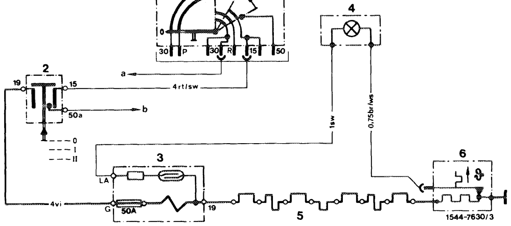
\f voltmeter indicates approx. 12 volts, check bulb and feed line of preglow indicator lamp (pay attention to tight seat of bulb in socket).
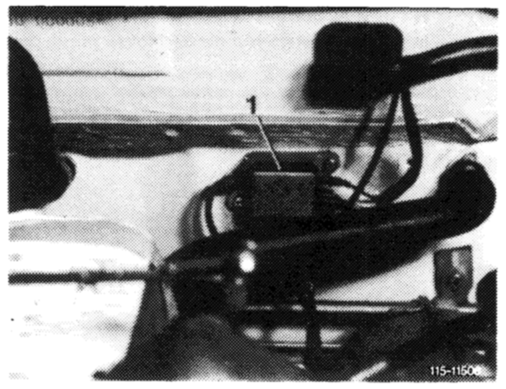
Pull coupler from thermo time switch and connect directly to ground. Actuate preglow system. If preglow indicator lamp lights up, replace thermo time switch.
If voltmeter indicates 0 volt, measure preglow current.
If approx. 50–55 amps are measured, the reed contact of fuse box is defective and the fuse box must be replaced.
resistance in preglow system is indicated or the battery is insufficiently charged.
Check connections of glow plugs and preglow starter switch for tight seat and recharge battery, if required.
D. With key start system engine 617 in model 115.1
a) Preglow system not preglowing
This complaint is the result of an interruption in circuit of preglow system.
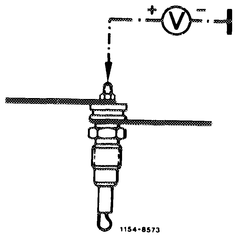
Adjust voltmeter to measuring range O—16 volts. Connect plus cable of voltmeter to input of glow plug of 5th cylinder and connect minus cable to ground. Turn key on steering lock starter switch to position ‘2’ and read voltage on voltmeter.
If voltmeter indicates 12 volts, look for interruption on glow plugs or their connections.
If voltmeter indicates 0 volt, look for interruption at preglow time relay or its connections.
1. Checking glow plugs for interruption
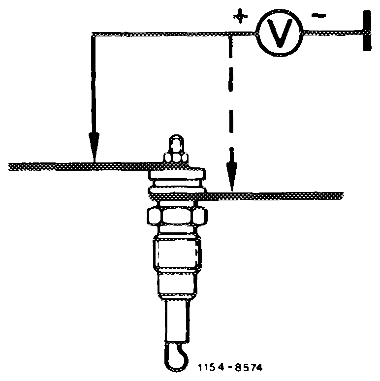
Connect minus cable of voltmeter to ground. Check voltage with plus cable of voltmeter at current input and output of the five glow plugs.
If 12 volts are measured at current input of a glow plug and 0 volt at output, this glow plug is interrupted and must be replaced.
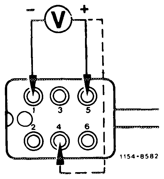
2. Checking preglowing time relay and its connection
Turn key of steering lock starter switch to position “ge.
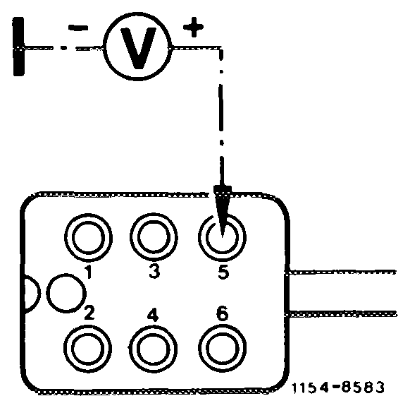
Pull coupler from preglow time relay. Connect minus cable of voltmeter to socket 1 of coupler. Check socket 5 and 4 one after the other with plus cable of voltmeter. If voltmeter indicates each time 12 volts, replace preglow time relay.
If voltmeter indicates 0 volt, connect minus cable of voltmeter to ground. Check at socket 5 of voltmeter with test cable.
If voltmeter indicates 12 volts, line 31 to socket 1 is interrupted.
If voltmeter indicates 0 volt, line 30 to socket 5 is interrupted.
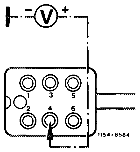
Then check socket 4 with plus cable of voltmeter.
If voltmeter indicates 0 volt, line 15 to socket 4 is interrupted.
In the event of complaints, check lines or connections for a loose contact.
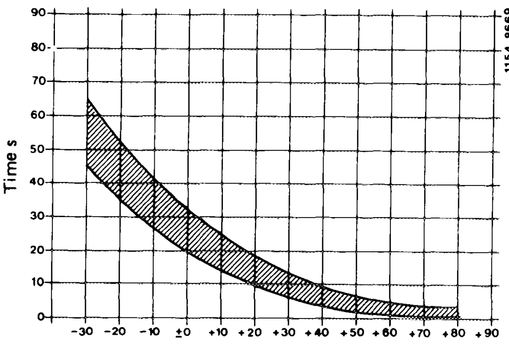
b) Preglow system preglows too slowly or too fast
Nominal time at: +20 °C approx. 12 seconds — 5 °C approx. 30 seconds
This complaint is caused by insufficient current flowing through preglow system as a result of transfer resistances or too much current as the result of a short-circuit.
Glow period at 52 amps Temperature °c
Measure glow current with ammeter first. For this purpose, connect ammeter to connection of glow plug for cylinder 5.
Glow current in preglow position: 50–55 amps.
Measured after approx. 15 seconds (battery charged at least 60 %).
If this glow current is not attained, measure voltage drop in preglow system with voltmeter.
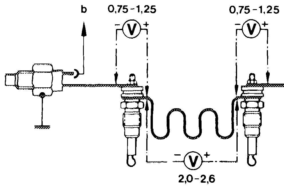
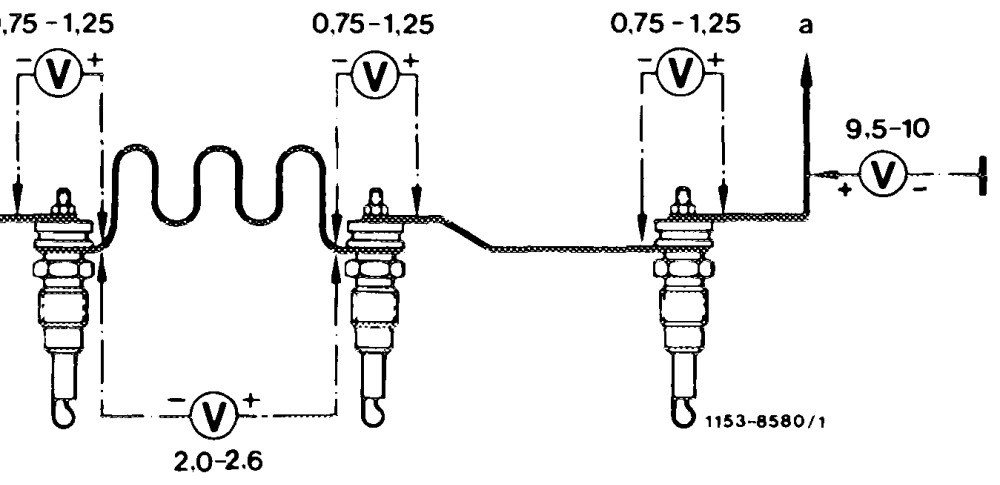
Check connections for tight seat.
a_ To fuse bTo preglow indicator lamp
When checking the voltage, connections of glow plugs, as well as the resistance conductors may not be shorted against ground (screwdriver against engine block), since this may lead to failure of preglow time relay.
If this glow current is exceeded, a short-circuit on preglow system is indicated.
If one of the glow plugs is lost by a short-circuit, change glow plug and measure preglow current once again.
c) Preglow system glows, preglow indicator lamp not indicating
1. Check line from glow plug cylinder 5 to preglow indicator for interruption.
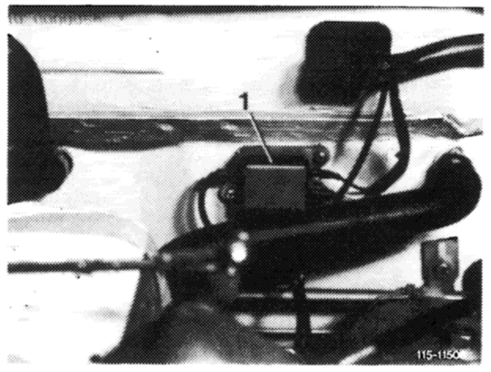
2. Check bulb of preglow indicator lamp in instrument cluster (pay attention to tight seat of bulb in socket).
Preglow system in general
Glow plugs are connected in series. The current flows across glow plugs from cylinder (5—) 4–3–2–1 to ground. Each glow plug is designed for a voltage of 0.9 volt at a max. current of 63 amps.
For this reason, the glow plugs are connected to resistance conductors, on which the remaining voltage is consumed (drops). The resistance conductors will also become red hot during preglowing.
The extent of the preglow current is determined by the total resistance in the preglow system (glow plugs plus resistance conductors).
Consequently, the cores for a burnt-out glow plug or a defective fuse under influence of an excessively high current flow can never be the preglow time relay. In such cases there is a reduction of total resistance in preglow system (e. g. short circuit to ground of one or several glow plugs by coking or by contact with prechamber.
A ground short on glow plug results in varying effects in preglow system. A glow plug ground short of the 4th or 5th cylinders, for example, will immediately make the fuse defective, while in the event of a glow plug ground short of the 3rd cylinder, the glow plug of the 4th cylinder will burn out (perhaps after several preglowing operations, as the case may be). Therefore, in the event of a burnt-out glow plug, always test the prior glow plug for a ground short and replace, if required.
This complaint is caused by an interruption in current circuit of preglow system.
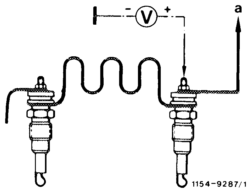
For accurate determination of fault source (whether glow bulbs or other components), connect voltmeter (measuring range 0O—30 volts) to current input of glow plug of 4th or 5th cylinder and to vehicle ground and read voltage (preglow system engaged).
Readout approx. 12 volts = interruption at glow plugs including connections (but not at preglow time relay).
Readout 0 volt = fuse defective, preglow time relay or activation of relay defective.
1. Check glow plugs for interruption
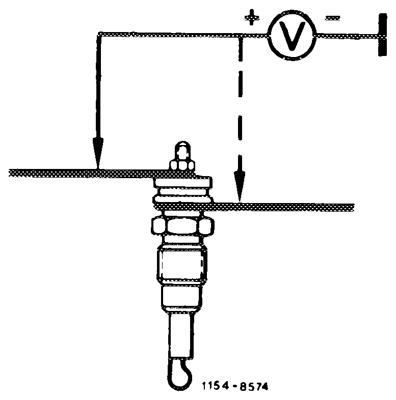
Connect negative cable of voltmeter to ground. Check voltage by means of positive cable of voltmeter connected to current input and output of 4 or 5 glow plugs (while disconnecting ground of glow plugs on 1st cylinder).
|f 12 volts are measured at current input of a glow plug and 0 volt at output, this glow plug is interrupted and must be replaced.
Attention!
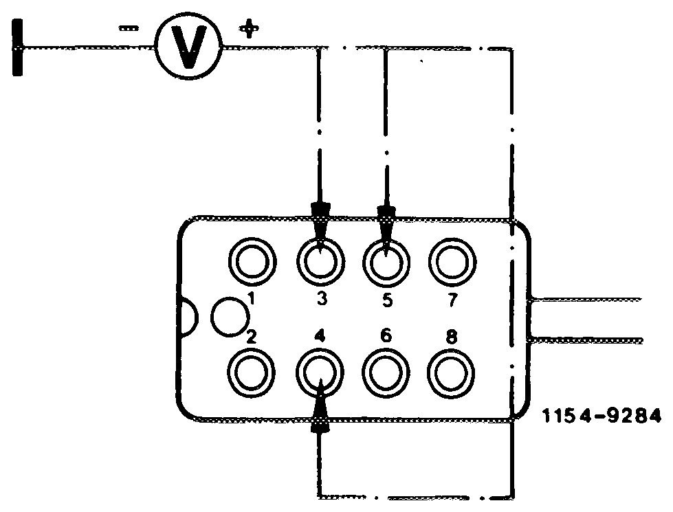
Never short connections of glow plugs or resistance conductors against ground (e. g. screw driver against engine block); this may result in failure of preglow time relay!
2. Testing preglow time relay and connections
Pull coupler from preglow time relay. Connect negative cable of voltmeter to vehicle ground. Check voltage at jack 5, 4 and 3 one after the other by means of positive cable, at jack 3, the starter should be actuated.
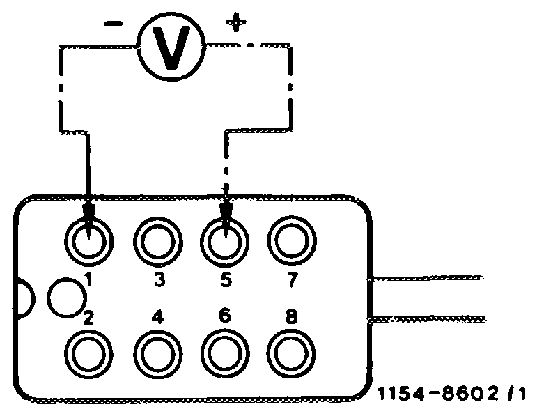
Then connect negative cable of voltmeter to jack 1 and positive cable to jack 5 and measure voltage.
Nominal values
Jack 5 = approx. 12 volts (terminal 30, continuous voltage) Jack 4 = approx. 12 volts (terminal 15, preglow system engaged) Jack 3 = approx. 12 volts (terminal 50, while starting) Jack 1 = approx. 12 volts (terminal 31, negative line)
If O volt is measured at one of the jacks, test respective line for interruption or repair interruption.
time relay is defective, replace preglow time relay.
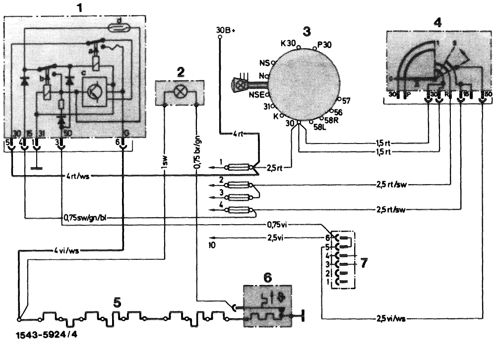
Wiring diagram
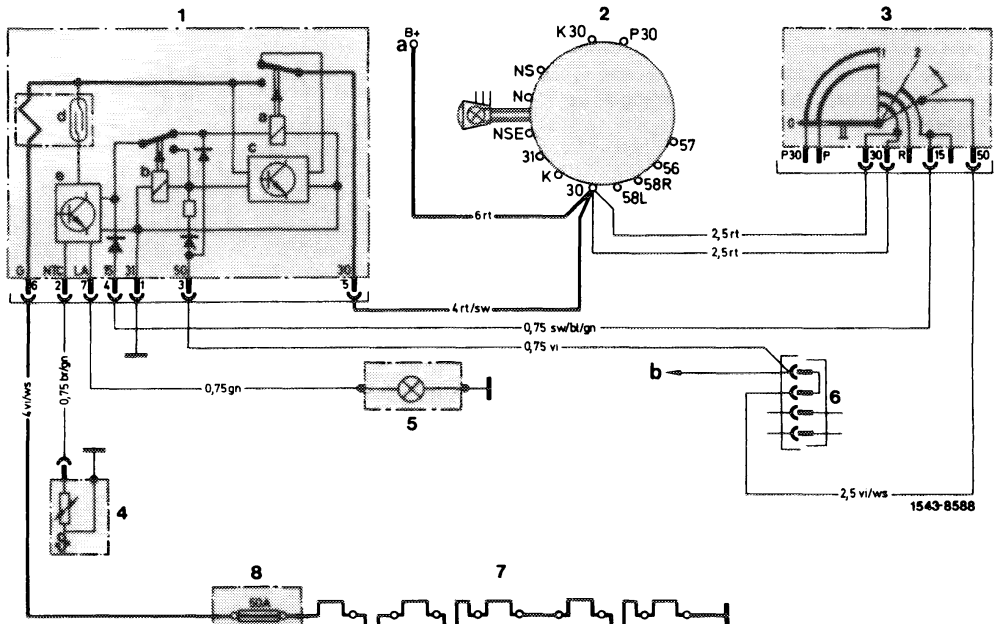

1 Preglow time relay 6 Line connector (engine harness)
2 Rotary light switch 7 Glow plugs and resistance conductors
3 Steering Jock starting switch 8 Fuse
4 Temperature sensor a To battery
5 b Ready-for-starting indicator To starter
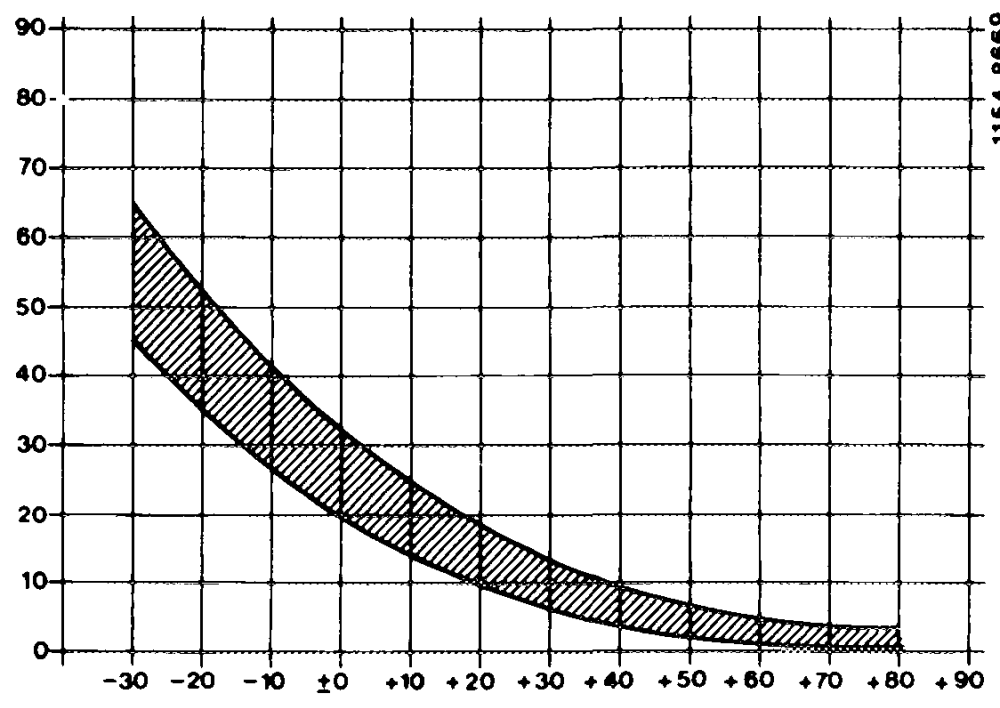
b) Preglowing system glowing too slowly or too fast
Nominal time at: +20 °C/68 °F approx. 12 seconds — 5°C/23 °F approx. 30 seconds
Time s Preglowing system preglows too slowly because not enough current can flow through transition resistances in glow plugs or on connections.
Preglowing system preglows too fast because too much current flows through one or several glow plugs due to ground short.
Temperature °C
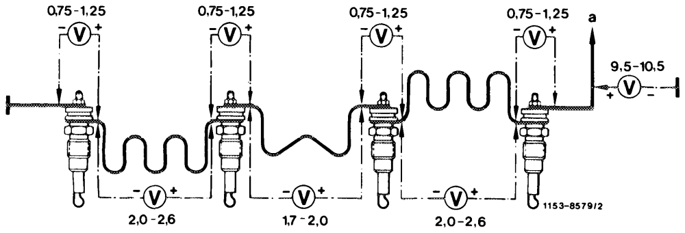
These faults can be found by measuring voltage drop of each glow plug. Measure voltage on glow plugs at current input and output with test points of voltmeter (measuring range O—3 volts).
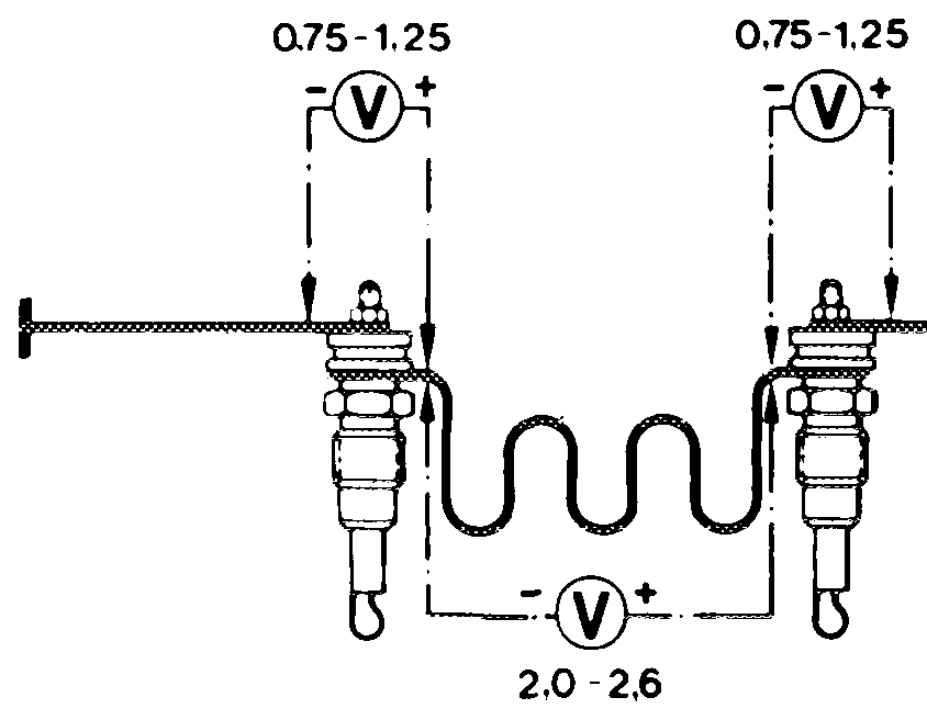
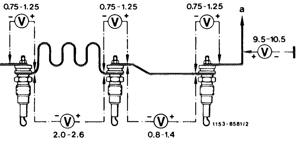
Engine 615, 616 a To fuse
Engine 617 a To fuse
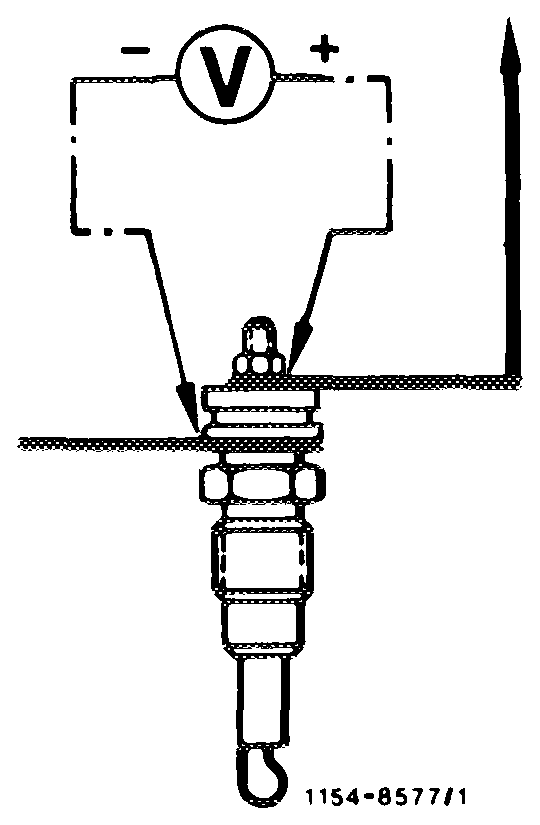
Measure as close as possible to glow plug, since otherwise measuring faults (higher voltage drop) will show up by including the resistance conductors into measuring.
When measuring, pay attention to risk of short circuit!
c) Preglowing system preglows, preglow indicator
not lighting up or not going out
If the preglow indicator lamp is not lighting up, pull coupler from temperature sensor — indicator lamp should now light up. In such a case, replace temperature sensor.
If the indicator lamp is not lighting up, pul! coupler
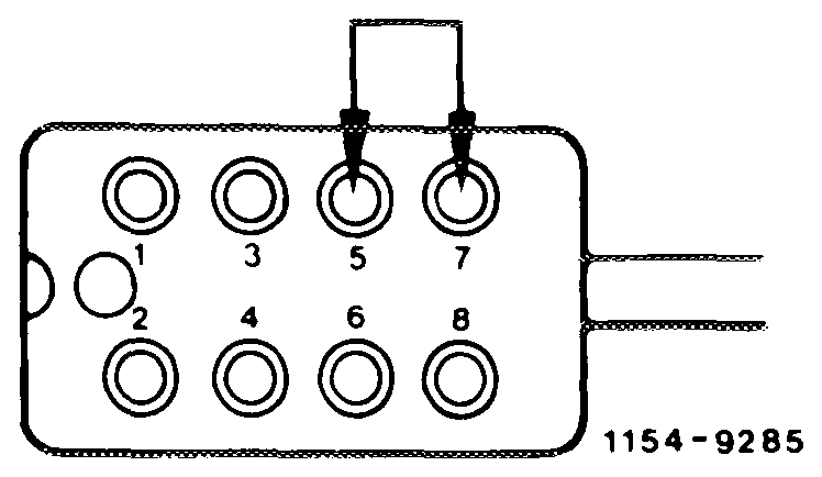
from preglow time relay and bridge jack 5 (terminal 30) with jack 7. If the indicator lamp is now lighting up, replace preglow time relay. If indicator lamp is not lighting up, check bulb or renew, or repair line interruption.
If the preglow indicator lamp is not going out after
attaining ready-for-starting condition, connect coupler of temperature sensor to ground. If indicator lamp is now going out, the temperature sensor is interrupted and should be replaced. If the indicator lamp is not going out, the preglow time relay is defective or the line to relay is interrupted. Replace preglow time relay or repair line interruption.
ohmmeter.
Resistance values according to coolant temperature:
0°C/O°F == approx. 8500 ohms
+25 °C/77 °F approx. 2500 ohms +80 °C/176 °F = approx. 300 ohms
At readout of 0 ohm, the temperature sensor has a short circuit, at readout % ohm, the temperature sensor is interrupted and should be replaced.
Wiring diagram
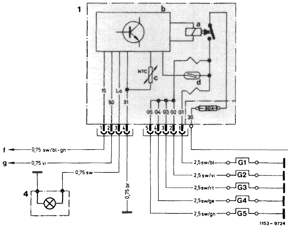
1 Preglow time relay a Power relay b Electronic unit c Temperature sensor (NTC-resistor) d Reed relay e To starter terminal 30 f To fuse box terminal 15 g To plug connection starter lockout and backup lamp switch terminal 50
4 Preglow indicator lamp G1— G5 Pencil element glow plugs
Note: On engine 615, 616, pencil element glow plug G5 is not required.
1. Test bulb and its line
Complaint:
Preglow indicator lamp not lighting up when preglowing system is switched on, in spite of ready-forstarting condition.
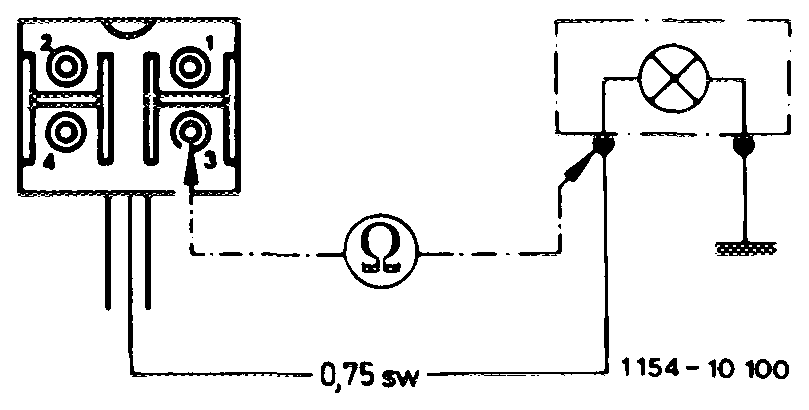
Remedy: ~ ed z =e Pe Pull 4-point coupler from preglow time relay, turn key into position ‘2, bridge jack 1 and 3 for coupler. 1153–10 099 If preglow indicator lamp is not lighting up, check bulb or renew, if required.
If bulb is in order, check black line from coupler of jack 3 of preglow time relay up to preglow indicator lamp for interruption, repair interruption.
If preglow indicator lamp is lighting up, the preglow time relay is defective and should be replaced.
2. Test main current circuit of preglow system for interruption
Complaint:
Preglow indicator lamp not lighting up, engine cannot be started.
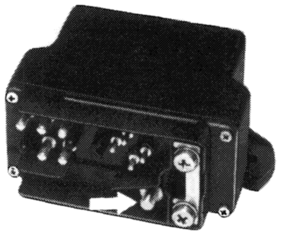
Measure voltage at terminal 30 of preglow time relay against ground by means of voltmeter.
If no voltage is indicated, check red line from starter terminal 30 up to preglow time relay terminal 30 for interruption, and, repair interruption, if required.
If voltage is indicated (approx. 12 volts), test 80-amp fuse for tight seat or interruption and renew, if required.
If so far no fault has been found, test voltage at jack OH 1 of 4-point coupler of preglow time relay against os ground. © 2. al
1154 ~10 101
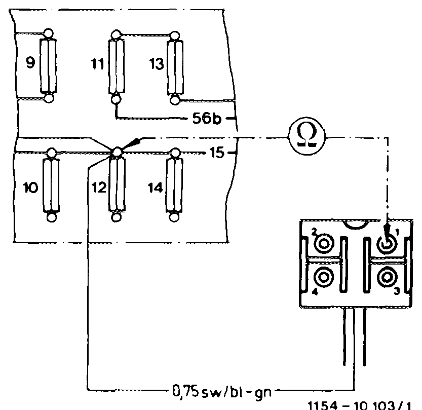
If no voltage is indicated with preglow system switched on, test black/blue-green line from fuse box terminal 15 up to coupler jack 1 of preglow time relay for interruption and repair interruption, if required.
If voltage is indicated (approx. 12 volts), connect voltmeter to jack 1 (terminal 15) and jack 4 (terminal 31) and test voltage (should be approx. 12 volts).
If no voltage is indicated, test brown line from jack 4 to ground for interruption and repair interruption, if required. 1154 – 10 104
\f so far no fault has been found, preglow time relay is defective, replace pregiow time relay.
3. Test pencil element glow plugs and their lines
Complaint:
Preglow indicator lamp not lighting up, engine firing poorly, one or several pencil element glow plugs or their lines to pencil element glow plugs may be interrupted.
Complaint:
Preglow indicator lamp lighting up, engine firing poorly after attaining ready-for-starting condition, a pencil element glow plug or a line to pencil element glow plugs of cylinders 2–4 (2–5) may be interrupted.
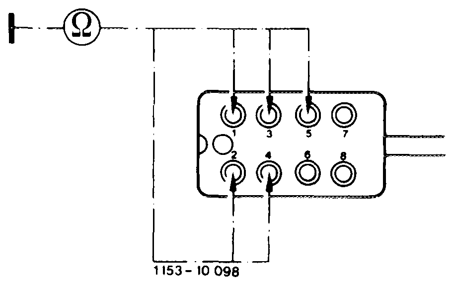
Measure resistance against ground (engine block) by means of ohmmeter one after the other as follows:
Jack 1 of coupler = pencil element glow plug cylinder 1 Jack 2 of coupler = pencil element glow plug cylinder 2 Jack 3 of coupler = pencil element glow plug cylinder 3 Jack 4 of coupler = pencil element glow plug cylinder 4 Jack 5 of coupler = pencil element glow plug cylinder 5
If resistance °° is measured, the respective pencil element glow plug or supply line or connection may be interrupted.
If measured resistance is smaller (e. g. at 20 °C/68 °F <1 ohm), the supply line and the pencil element glow plug is in order.
Note: It is possible that (as the result of unfavorable tolerances) the indicator lamp will indicate a fault only after 2 pencil element glow plugs in cylinders 2–5.
To make sure that the fault indication in preglow time relay is not defective, disconnect 2 pencil element glow plugs of cylinders 2–4 (2–5) in such a case and repeat preglow procedure.
If warning lamp now indicates a fault (not lighting up), the preglow time relay is in order.