Adjusting accelerator control
WIS 30-1010
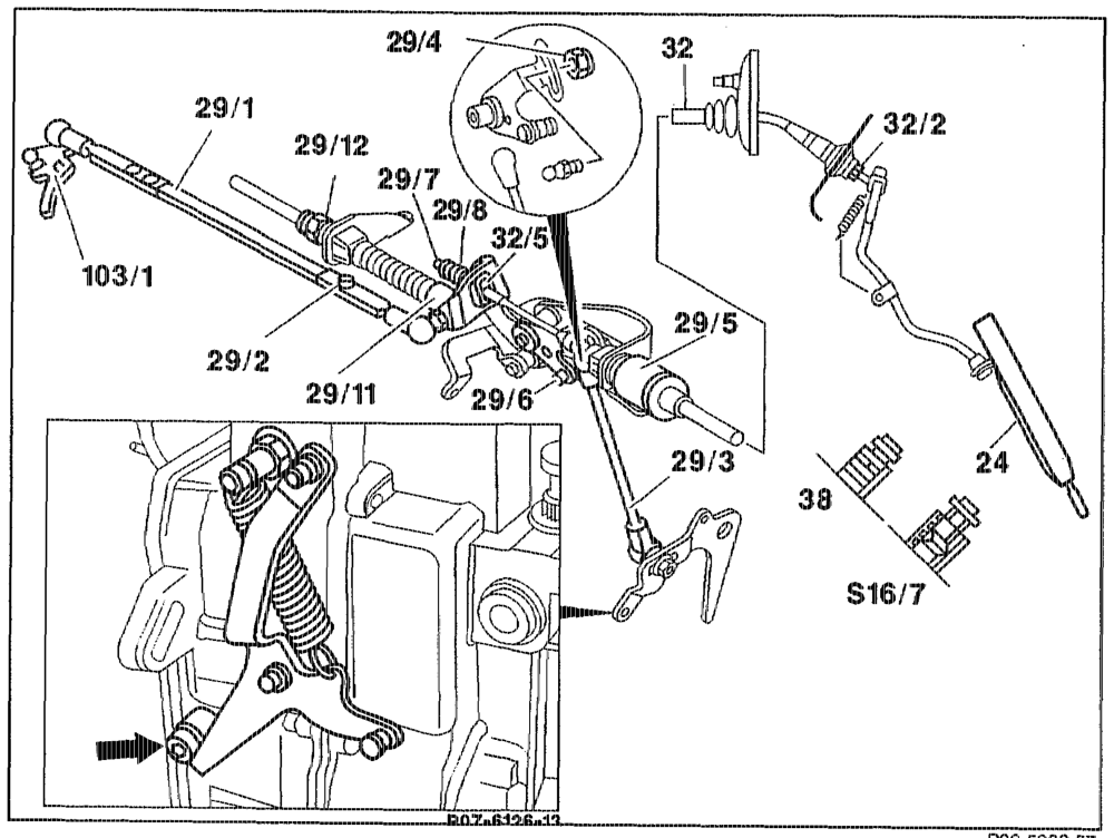
Operation no. of operation texts and work units or standard texts and flat rates:
P30-5302–57
Accelerator control lever, linkage and Bowden cable (82) 22… 0… 0. ccc eee eee check for ease of movernent and condition, replace parts if necessary.
Idle speed setting at engine side
Accelerator pedal (24) …… see eee eee in idle speed position. Hexagon bolt (29/2) at connecting rod to vacuum control flap …… cece eee see slacken. Nut (29/4) at ball head of connecting rod (29/3) 2… 2.0.0.0, wee wee slacken.
sete FA 30.1630-101 0/1 tum until the roller (29/6) in the fulcrum lever is resting free of tension against end stop.
Note After adjusting, there must not be any play between spring plate (29/7) and spring (29/8). Nut (29/4) at ball head of connecting VOD (29/8) oc ee eee ee ee tighten.
Note If automatic transmission fitted, attach ball socket of control pressure cable (29/11) free of tension. To do this, pull control pressure cable forward until a slight resistance is felt and turn bolt (29/12). Relay lever (103/1) of vacuum control flap ….. turn until it is resting against idle speed stop. Connecting rod (29/1) 2… eee ee eee pull apart at the riveted side until the idle travel is eliminated. Hexagon bolt (29/2) of connecting rod to vacuum control flap 2.2… ee eee tighten.
Full throttle, manual transmission Full throttle stop (38) ….. see e eee eee see release by turning to the left. Accelerator pedal (24) 2… cece eee eee push through with engine switched off until adjusting lever just reaches full throttle stop (arrow) on injection pump; pull out stop pin slightly. Lock full throttle stop (38) in the adopted position by turning to the right.
Full throttle, automatic transmission
Accelerator pedal (24) 2.0… cee eee eee push as far as the stop with engine switched off (do not operate kickdown switch ($16/7)), turn adjusting nut (29/5), if necessary until adjusting lever just reaches full throttle stop (arrow) on injection pump.
eon = RA 30.1630-1010/2

Idle speed position, chassis side Accelerator pedal (24) in idle speed position …. there must not be any play between driver spring (29/8) and guide piece (32/5); alter with adjusting nut (32/2), if necessary, inside vehicle. Bowden cable (32) see grease between end piece and guide piece (32/5) with anticorrosion grease 000 989 87 51 10.
) measured from center-to-center of ball sockets
Notes Restoring spring modified. Strengthened restoring spring to ensure accelerator control damper moves back when engine idling.
Production breakpoint: as of June 1993
Model Engine Engine end no. automatic transmission
124.104/107/126/129/ 605.9114 000451 186
4.131/191 606.910 000173
Restoring spring at injection pump with increased spring force.
Production breakpoint: as of September 1993
Model Engine Engine end no. manual transmission
124.104/107/126/129/ 605.911 005093 186
124.131/191 06.910 001671
«singe = RA P1RBO7.99.1699-1010/3