Coolant circuit function
WIS 20-1000A
GF20.00-P-1000A 1
Coolant circuit function B5 GF20.00-P-10004
ENGINE 602.982 /983, 605, 606 / (except, 606.964)
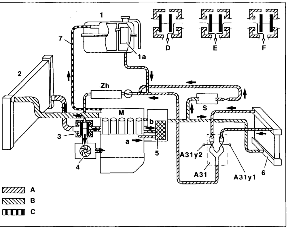
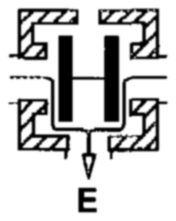
Diagram of coolant circuit engine 602.982
Coolant expansion reservoir with single-stage cap 1.4 bar Silica gel reservoir Radiator MWA WD Coolant thermostat Coolant pump Oil filter with oil-water heat exchanger Heating system heat exchanger n Vent pipe to coolant expansion reservoir Heating system delivery unit A31 Left duovaive A3lyl Right duavalve A3ly2 Coolant return flow Coolant feed Bypass mode temperature < 85 °C
P20.00-0238–06
#B5 It ™ GF20.00-P-1000A
Mixed mode temperature > 85 °C and < 94 °C thermostat opens. Start of flow through radiator Cooling mode temperature > 94 °C thermostat open, full flow through radiator Engine Windshield washer fluid reservoir, coolant heated wn Zh Heater booster < 5 °C and > 70°C
#BS5 GF20.00-P-1000A 3
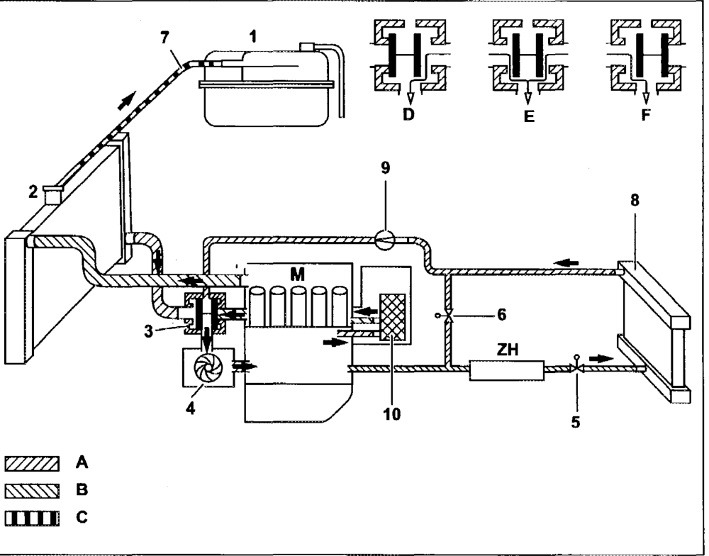
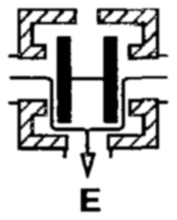
Diagram of coolant circuit engine 602.983
Coolant expansion reservoir SOMANANUAWN MOODS — Radiator Thermostat Coolant pump Heating valve Electric valve Overflow hose Heating system heat exchanger Electric pump Fuel heat exchanger Coolant return flow Coolant feed Ventilati entilation Bypass mode temperature < 85°C °
Mixed mode temperature >85°C and < 94°C Cooling mode temperature > 94°C 7”
M Engine ZH Stationary heater
P20.00-0398–06
#B5 GF20.00-P-1000A
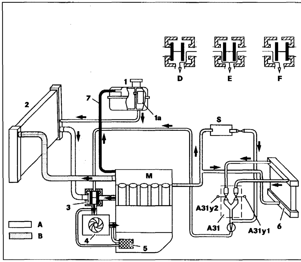
Diagram of coolant circuit engine 605 with oil-water heat exchanger at oil pan
1 Coolant expansion reservoir with silica gel reservoir (1a)
2 Radiator Coolant thermostat (position: ly engine at operating temperature) Coolant pump OMA N Oil-water heat exchager at oil pan Heating system heat exchanger Vent pipe to coolant expansion reservoir A31 Heating system delivery unit A3tly1 Left duovalve A3tly2 Right duovalve A Coolant return flow B Coolant feed D Bypass mode temperature < 85 °C
P20.00-0236–06
# BS GF20.00-P-1000A
Mixed mode temperature > 85 °C and < 94 °C thermostat opens. Start of flow through radiator Cooling mode temperature > 94 °C thermostat open, full flow through radiator Engine Windshield washer fiuid reservoir, coolant heated wa
aan #B5 GF20.00-P-1000A 6

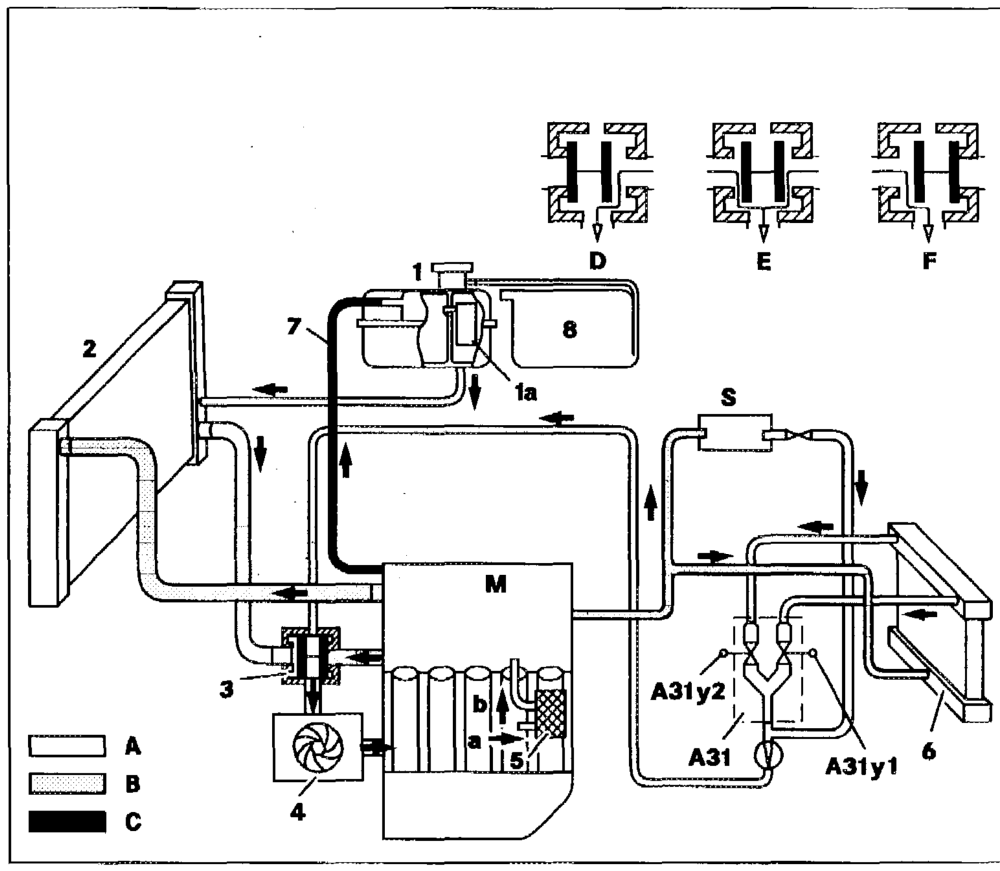
Diagram of coolant circuit engine 605 with oil-water heat exchanger at oil filter
7 Coolant expansion reservoir with silica gel reservoir (1a)
2 Radiator
3 Coolant thermostat (position: engine at operating temperature)
4 Coolant pump
5 Oil filter with coolant heat exchanger
6 Heating system heat exchanger
7 Vent pipe to coolant expansion reservoir
8 Engine 605.960: overflow reservoir (is replaced by 2-stage cap at expansion reservoir as phased-in modification) A31 Heating system delivery unit A3ly? Left duovalve A31ly2 Right duovalve A Coolant return flow B Coolant feed C Vent pipe to coolant expansion reservoir
Bypass mode temperature < 80 °C md Mixed mode temperature > 80°C and < 94 °C thermostat opens. Start of flow through radiator Cooling mode temperature > 94 °C thermostat open, full flow through radiator Engine rene Windshield washer fluid reservoir, coolant heated From crankcase To cylinder head
# BS GF20.00-P-1000A 8

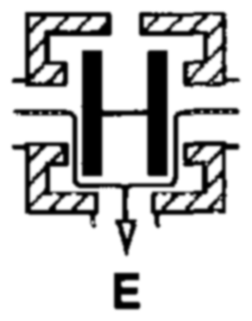
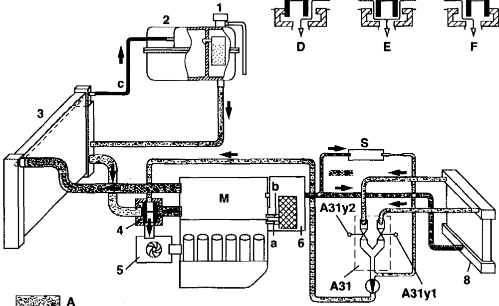
Diagram of coolant circuit engine 606.912 in model 210 with oil-water heat exchanger at oil filter
1 2-stage cap
2 Coolant expansion reservoir with gel reservoir
3 Radiator
4 Coolant thermostat (position: engine at operating temperature) Coolant pump Oil filter with coolant heat exchanger Heating system heat exchanger Heating system delivery unit A31 Left duovalve A3tly1 Right duovalve A3ly2 Coolant return flow Coolant feed Vent pipe to coolant expansion reservoir Bypass mode temperature < 85 °C
P20.00-0232–06
#BS GF20.00-P-1000A
Mixed mode temperature > 85 °C and < 94°C thermostat opens. Start of flow through radiator Cooling mode temperature > 94 °C thermostat open, full flow through radiator Engine crewene Windshieid washer fluid reservoir, coolant heated From crankcase To cylinder head
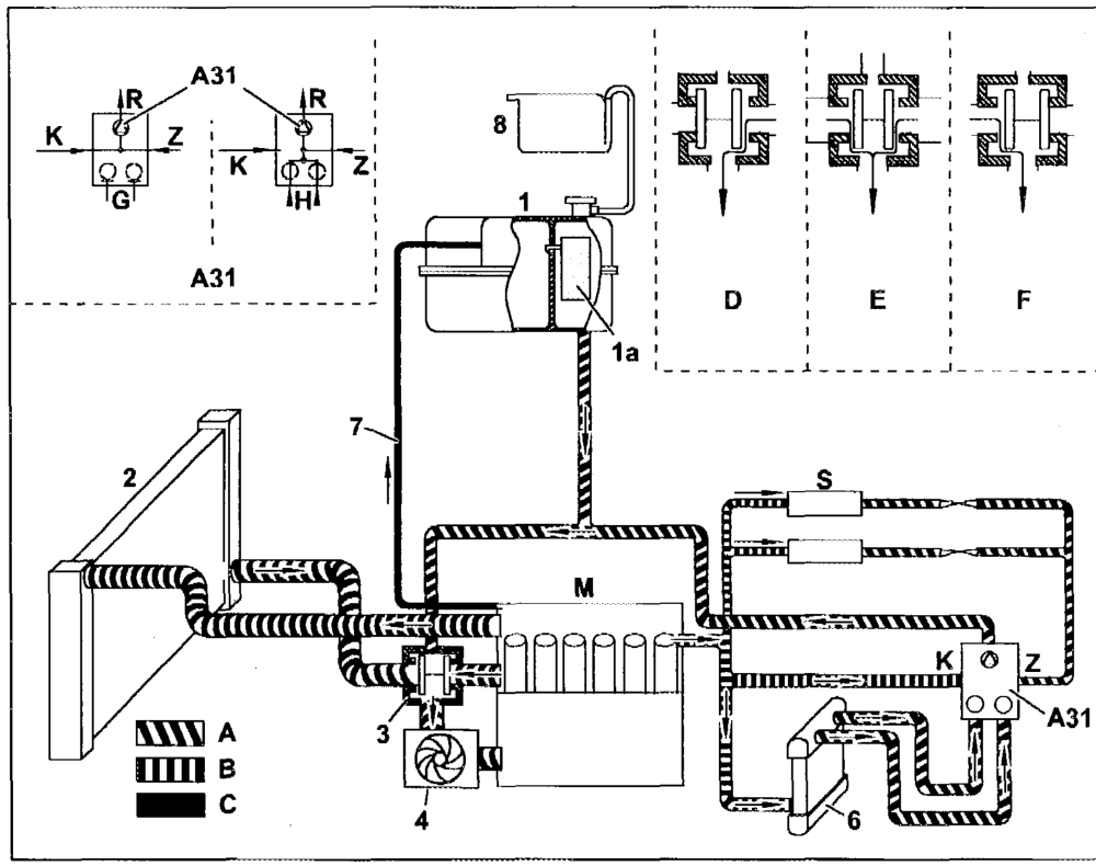
#B5 GF20.00-P-1000A 10
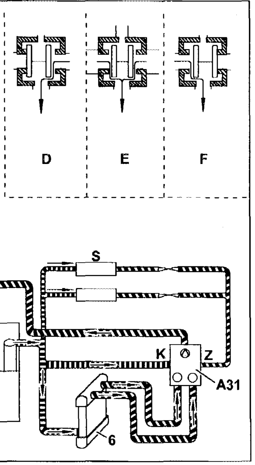
Diagram of coolant circuit engine 606.961 in model 140 with engine oil cooler in wheelhousing
1 Coolant expansion reservoir with silica gel reservoir (1a)
2 Radiator
3 Coolant thermostat (position: engine at operating temperature)
4 Coolant pump
6 Heating system heat exchanger
7 Vent pipe to coolant expansion reservoir
8 Overflow reservoir A31 Heating system delivery unit A3ly1 Left duovalve A31y2 Right duovalve A Coolant return flow B Coolant feed Cc Vent pipe to coolant expansion reservoir
P20.00-0275–06
#B5 GF20.00-P-1000A 1 lb mo Bypass mode temperature < 80°C Bypass NUDE Mixed mode temperature > 80 °C and < 94°C thermostat Engine opens. Start of flow through radiator Return flow of heating system delivery unit (A31) Cooling mode temperature > 94 °C thermostat open, full Windshield washer fluid reservoir, coolant heated n flow through radiator Feed of heating system delivery unit (A31) Heating mode off, valves pressurized (vehicle switched off, engine-off cooling) Heating mode, valves not pressurized

An #B5 GF20.00-P-1000A 12

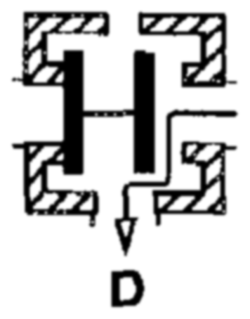
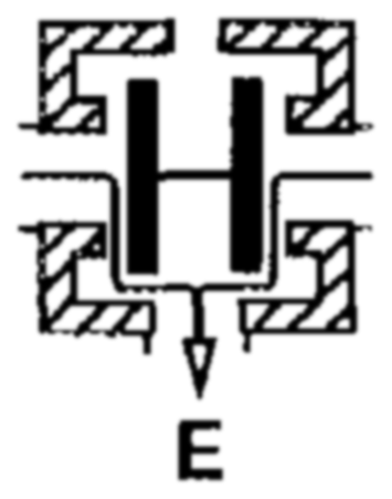
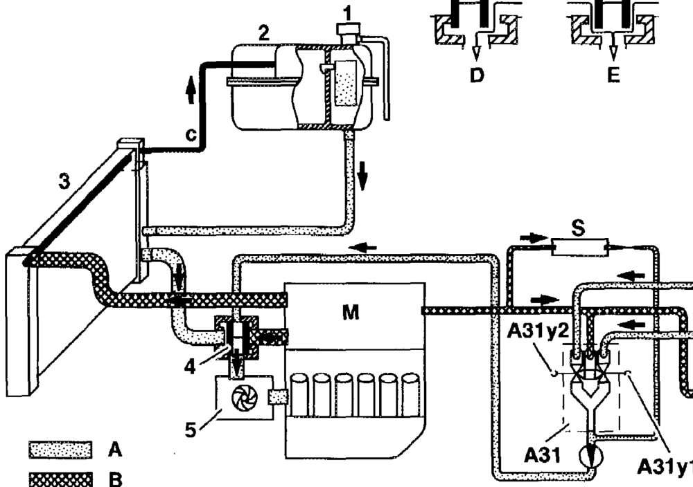
Diagram of coolant circuit engine 606.962 in model 210 with engine oil cooler in wheelhousing
1 2-stage cap
2 Coolant expansion reservoir with gel reservoir
3 Radiator
4 Coolant thermostat (position: engine at operating temperature)
5 Coolant pump
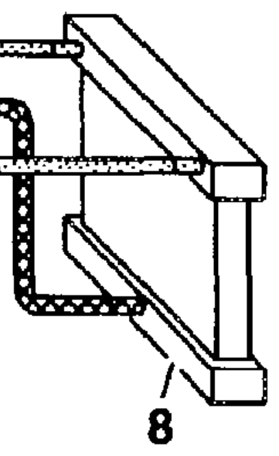
8 Heating system heat exchanger A31 Heating system delivery unit A3ly1 Left duovalve A3ly2 Right duovalve A Coolant return flow B Coolant feed Cc Vent pipe to coolant expansion reservoir D Bypass mode temperature < 85 °C flow possible through passenger compartment E Mixed mode temperature > 85 °C and < 94°C thermostat opens. — P20.00-0312-57 Start of flow through radiator
#B5 GF20.00-P-1000A 13
Cooling mode temperature > 94 °C thermostat open, full nm
flow through radiator M Engine Windshield washer fluid reservoir, coolant heated ~”
bh” GF Function of 2-stage cap GF20.30-P-1000A L8.