Function of hydraulic engine mounts
WIS 22-210
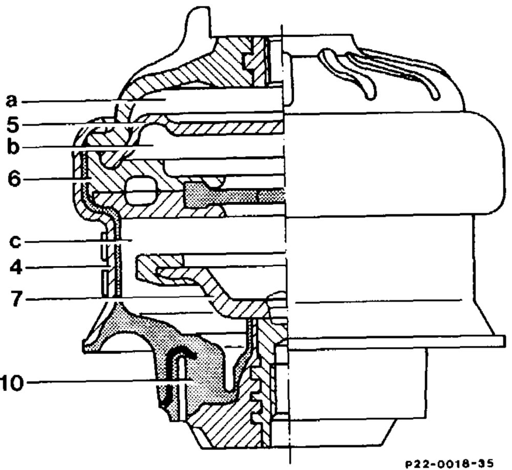
4 Engine mount
5 Diaphragm
6 Plastic disc with annular passage
7 Rubber stop plate
10 Rubber mount a Diaphragm space b = Upper chamber c Lower chamber
The hydraulic engine mounts are filled with a All parts of the engine mounting are glycol mixture. The glycol mixture is located in maintenance-free. two chambers (b and c). The two chambers are The hydraulic engine mounts have identical load connected to each other by an annular passage in the plastic disc (6). The glycol mixture flows bearing capacity on the left and right but differ along the annular passage into the respective depending on the various engine and chamber as the springs compress or rebound. transmisston versions. A diaphragm (5) limits the upper chamber (b). They are identified by a colourad dot on the Air is admitted to or released from the housing in order to avoid any mixups. diaphragm space (a) through two passages. The rubber stop plate (7) in the lower chamber (c) is firmly connected to the bearing foot and limits the spring travel during compression. The engine mount (4) is attached by a hexagon bolt to the engine supporting bracket and by a hexagon socket bolt to the frame cross member.