Testing oil level indicator
WIS 18-220
Operation no. of operation texts and work units or standard texts and fiat rates
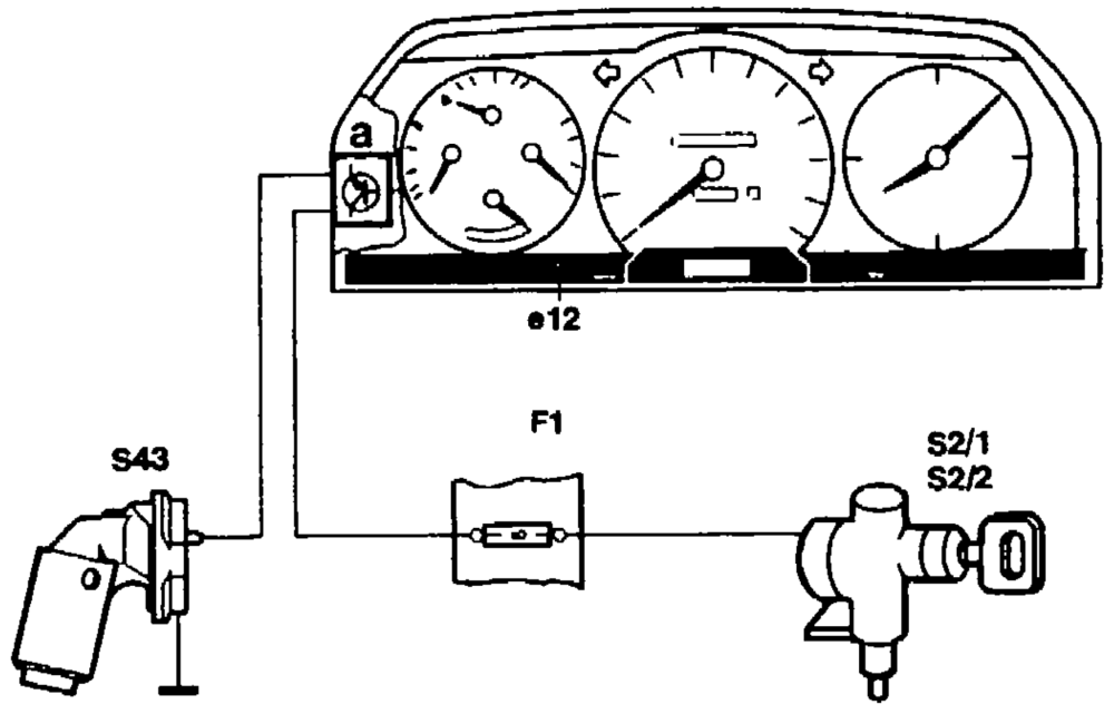
A1_ Instrument cluster Fl Fuses A $2/1,82/2 Ignition lock a Electronics e12 Oil level indicator lamp P18-0036-35A
Note Engine 602.982 in model 210 Operation of oil level indicator as described in 18-225. Actuated electrically through the DFI control module. Testing see Diagnosis Manual Volume 4 and HHT.
Complaints
A. Indicator lamp shows a steady light when engine running and oil level correct.
B. Indicator lamp does not light up when key in position „2”.
C. Indicator lamp does not light up when engine running, oll temperature > +60 °C and oil level below “min”.
wai §=RA 18.1045-220/1
Resistance at max. oil level <1Q
| Resistance at min. oil level | wo Q |
| Battery voltage | approx. 12 V |
Commercially available tool
Multimeter e.g. Sun, DMM-5
A. Indicator lamp shows a steady light
when engine running and oil level
correct
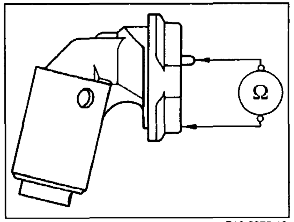
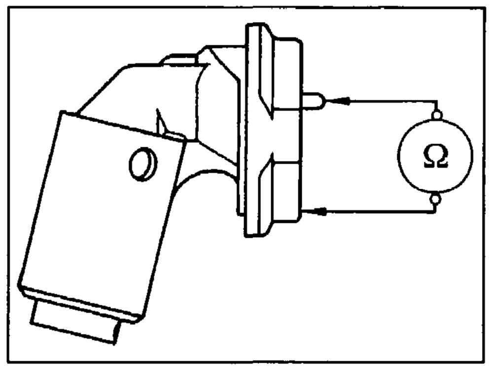
Test oil level sensor by detaching connector. Measure resistance between oil level sensor on ground.
Readout: < 1 Q
Yes No
Renew oil level sensor.
P18-0075–13
Vv
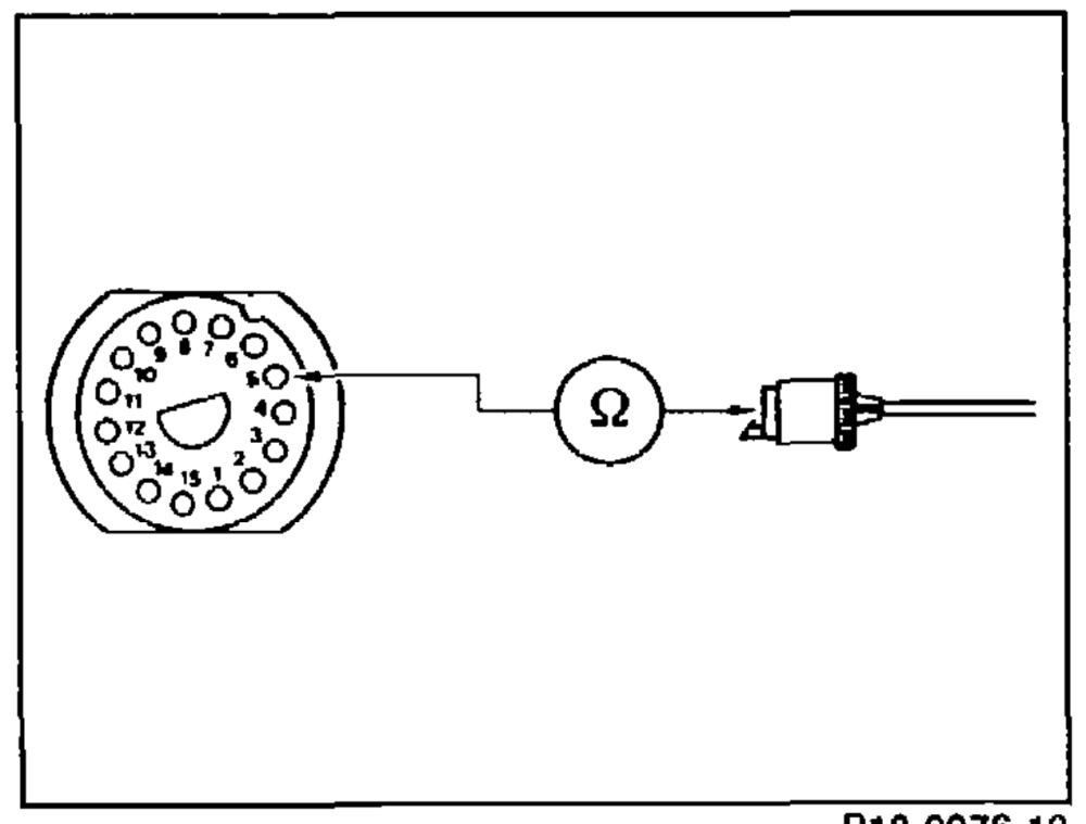
Test cable by removing 15-pin connector from instrument cluster. Measure resistance between contact 5 of 15-pin connector and contact of oil level sensor plug.
Readout: < 1 Q
Yes No
Renew wiring harness. P18-0076–13
WV
Renew gauge.
End of test
Test operation of bulb. Result: bulb in order.
| Yes | No | ||||
| Renew bulb. | |||||
| Vv | |||||
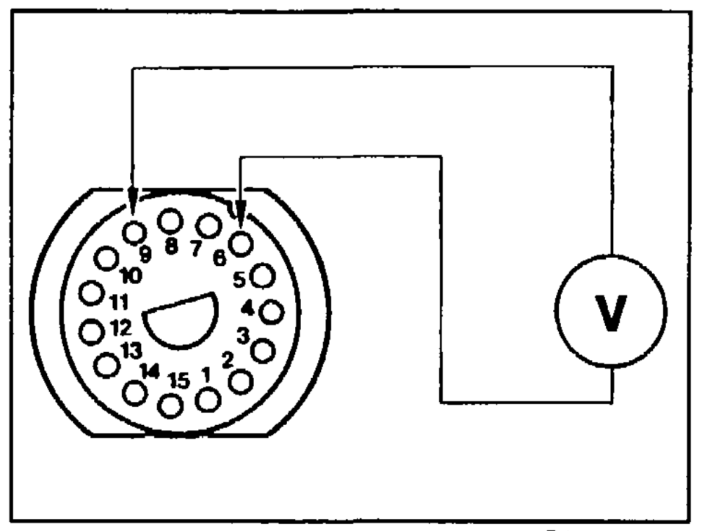
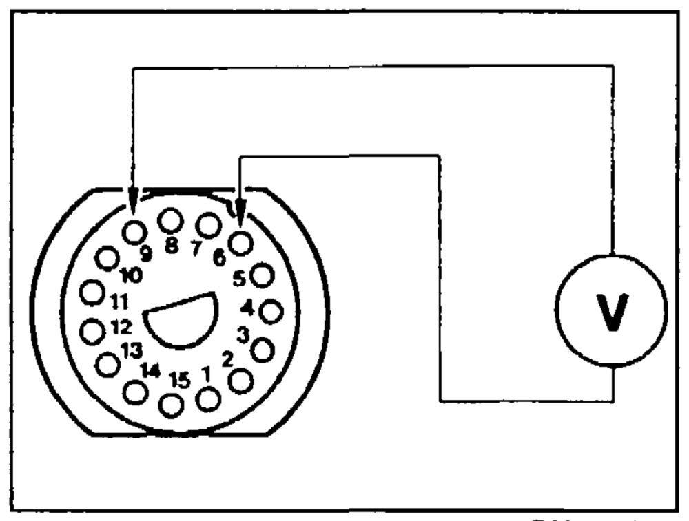
| Remove instrument cluster. Measure voltage | y instrument cluster. Measure voltage | ||||
| with multimeter at contacts 6 and 9 of the 15- pin connector. Readout: approx. 12 V | |||||
| Vv | |||||
| Renew | harness. | ||||
| wiring | P20-0076–13 | ||||
| Vv | |||||
| Renew gauge. | gauge. | ||||
| _v | |||||
| End of test | est | ||||
elie §=RA 18.1045-220/3
C. Indicator lamp does not light up when
engine running, oil temperature
> +60 °C and oil level below „min”
| Test operation of bulb. Result: bulb in order. | cute bulb inorder. | ||||
| Yes | No | ||||
| v | |||||
| Renew bulb. | |||||
| Vv | |||||
| Test oil level sensor by detaching connector. Test resistance between oil level sensor and ground. Readout: © 2 | |||||
| Yes | No | ||||
| Renew oil level sensor. | |||||
| Vv | P18-0075–13 | ||||
| Test cable by detaching 15-pin connector from instrument cluster. Measure voltage between contacts 6 and 9 of the 15-pin connector. Readout: approx. 12 V | |||||
| Renew wiring harness. | |||||
| P20-0076–13 | |||||
| Vv | |||||
| Renew gauge. | renew gauge. | ||||
| End of test | =nd of test | ||||
im =A 18.1045-220/4
Model 124
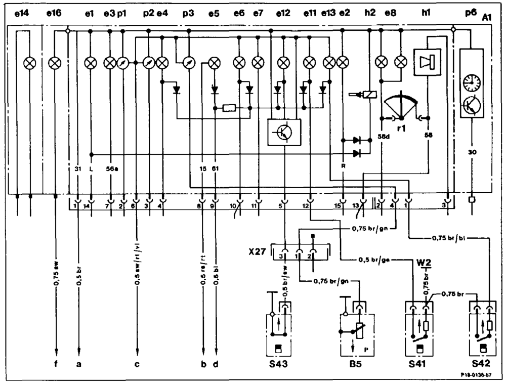
Wiring diagram engine oil level indicator, coolant level indicator, windscreen washer level indicator (see Wiring Diagrams Volume 3 and Volume 4 for further information) Al Instrument cluster B5 Oil pressure gauge sensor e1 Left turn-signal indicator lamp $41 Coolant level indicator lamp switch e2 Right turn-signal indicator lamp $42 Windscreen washer indicator lamp switch e3 High beam indicator lamp $43 Oil level indicator lamp switch
4 Fuel reserve warning lamp We Ground, front right (next to lamp unit) e5 Battery charge indicator lamp X27 Connector, starter wiring harness e6 Brake pad wear indicator lamp Main ground (behind instrument cluster) W1 a
87 Brake fluid and parking brake indicator lamp Fuse 7 terminal 15 b Fuse 5 terminal 15 68 instrument lighting c e11 ~~ Coolant level indicator lamp Lamp indicator unit d e12 Oil level indicator lamp Preglow time relay terminal La f e13 Windscreen washer level indicator lamp e14 ~— Exterior lamp failure indicator lamp e16 ~~ Preglow indicator lamp hi Warning buzzer pl Coolant temperature gauge p2 Fuel gauge p3 Oil pressure gauge pé Electronic clock