Removing and Installing Exhaust Manifold (continued)
WIS 15-0705
System
General On a diesel engine, cornbustion occurs when the fuel is injected into the highly compressed and thus greatly heated combustion air and selfignites.
When the engine is cold, the se i temperature is not reached by compression alone. It is therefore necessary to provide a preglow system to raise the temperature of the compressed air, enabling the cold engine to start by igniting fuel particles on the glow plugs.
The duration of preglow depends on the ambient temperature.
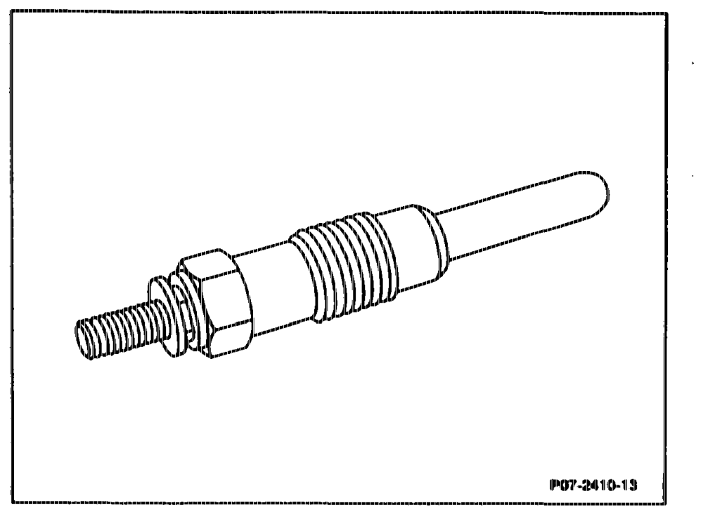
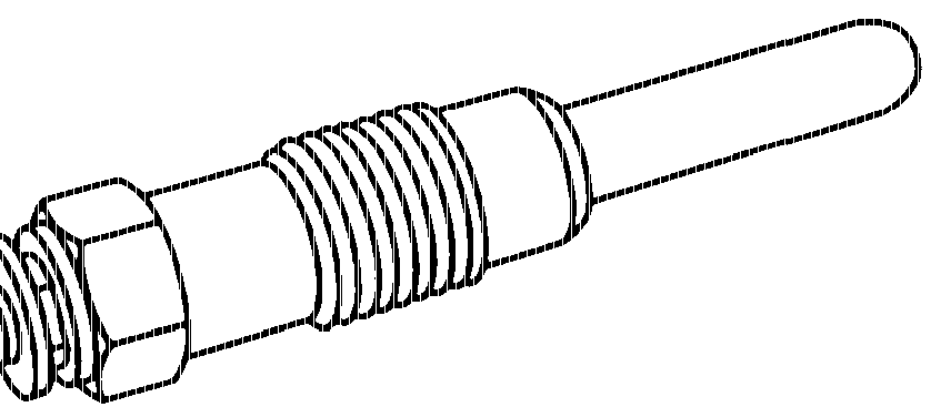
tart Pencil-type Glow Design of the Quic Plugs The pencil-type glow plugs consist essentially of a housing with a M12 1.25 external thread and eating element press-fitted into the housing.
The single-pin connecting pin is screwed into the housing by a non-detachable brass round nut. The pencil-type glow plugs are designed for a voltage of 11.5 Volts and are connected in parallel.
utihis = RA 1§.1010-0705/1
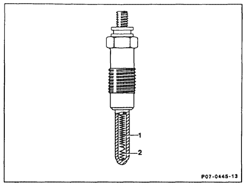
The heating element consists of a seriesconnected heating and control winding.
1 Control winding 2 Heating winding
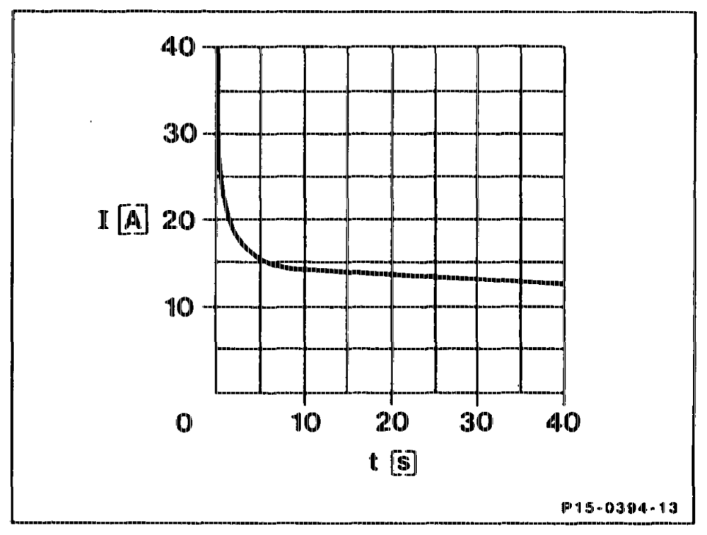
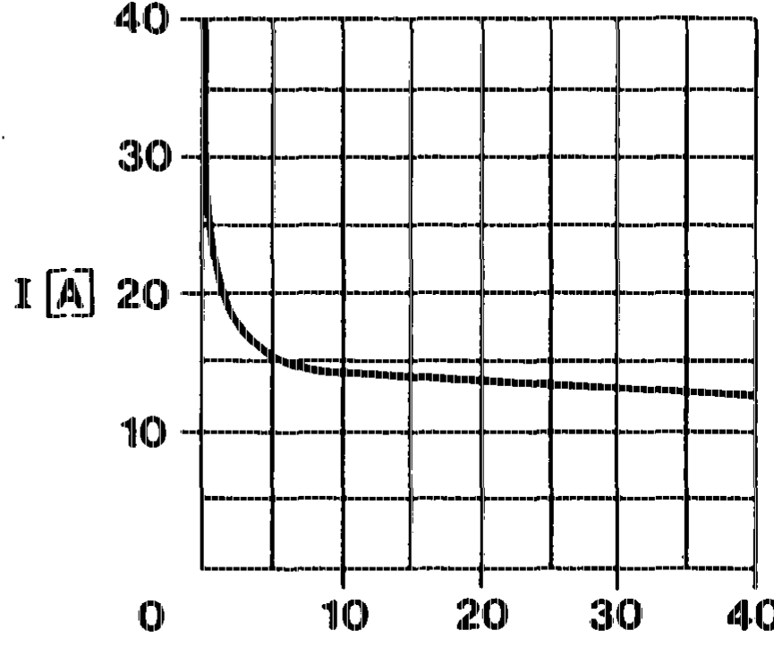
When the glow system is switched on, a current of approx. 30 amperes flows to each glow plug. The heating winding heats the glow plug very rapidly. The control winding increases its resistance as the temperature rises and limits the current to approximately 8–15 amperes. The glow plug is thus protected against overload.
Current curve of quick-start pencil-type glow plug
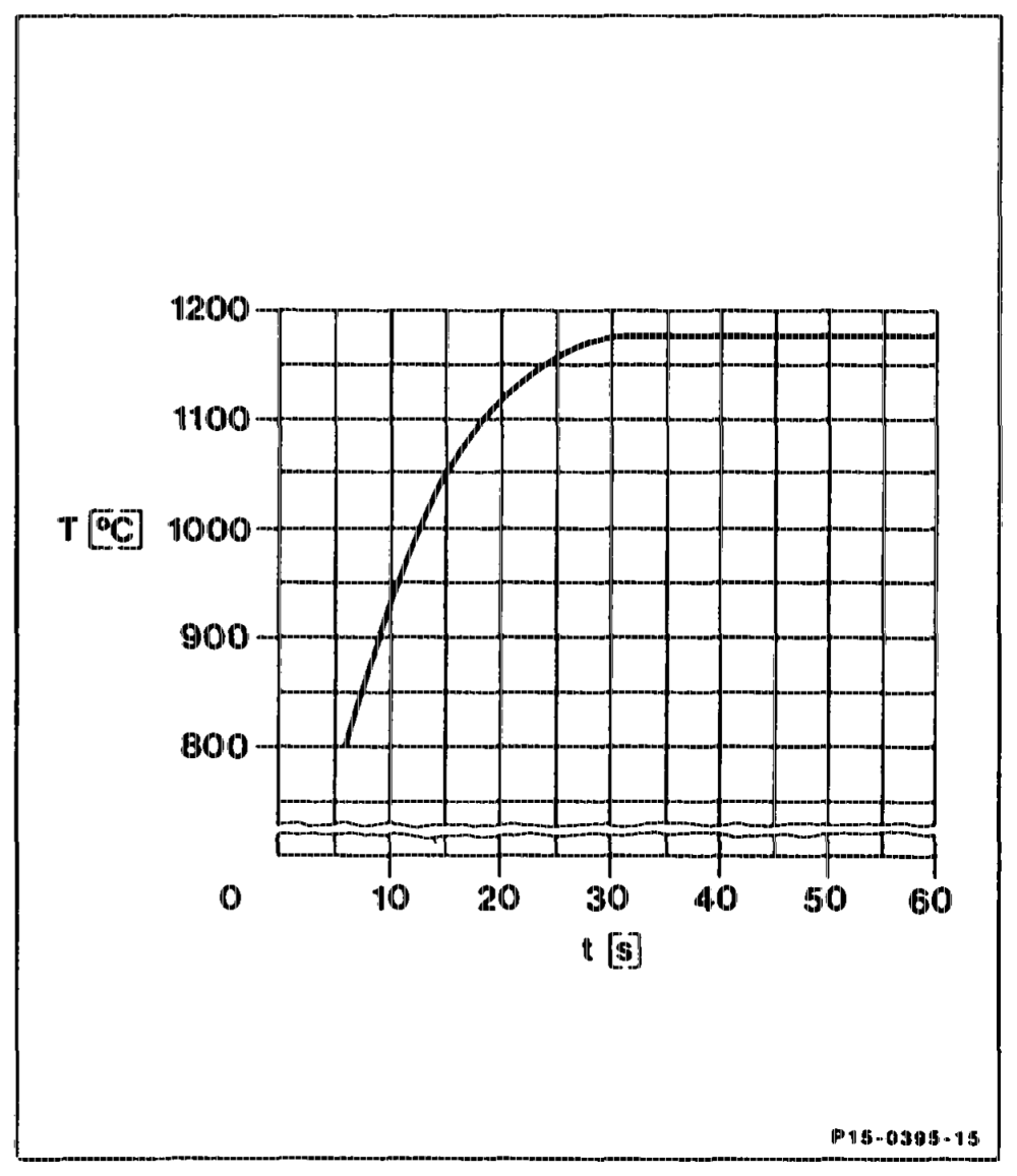
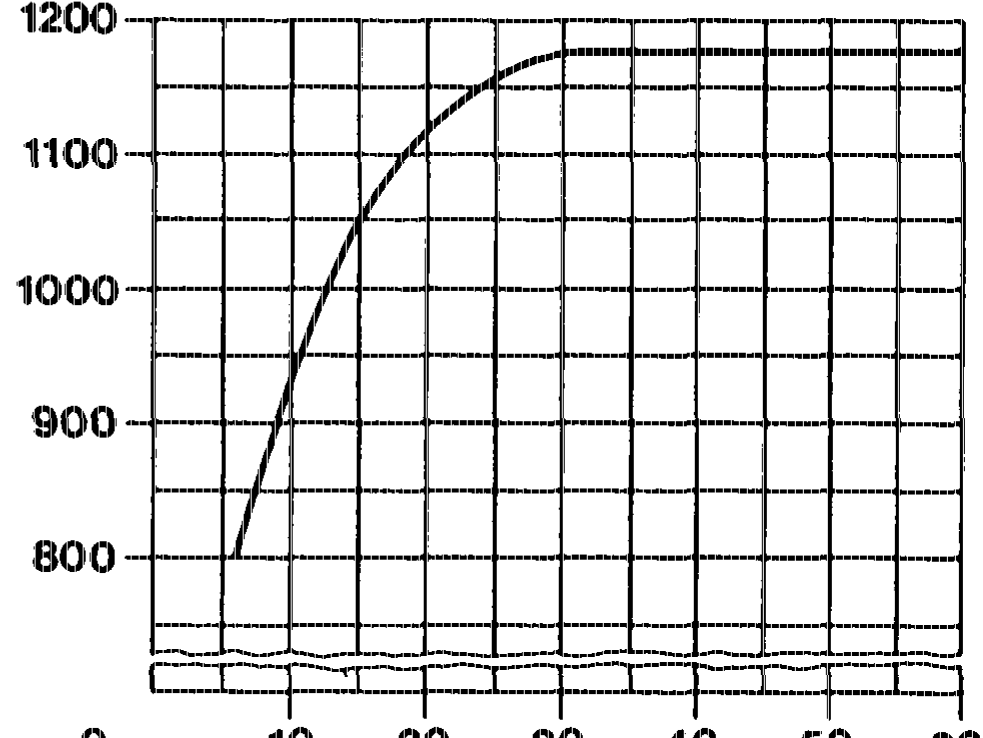
After a glow period of 9 seconds, a heating element temperature of 900 °C is reached, the maximum temperature of 1180 °C being reached after 30 seconds.
Temperature curve of quick-start pencil-type glow plug
aptitin RA 15.1010-0705/2
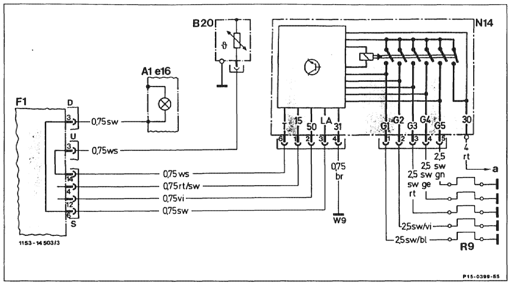
Wiring Diagram Engine 602.961, Model 201.128 A1e16 Instrument cluster, preglow indicator R9 Glow plugs B20 Temperature sensor (preglow) wg Ground, front left (next to lamp unit) F1 Electrical centre a X35 terminal block, terminal 30 N14 Preglow time relay
eotihijy =RA 15.1010-0705/3
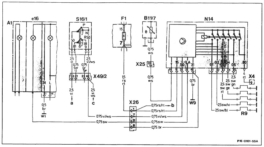
Wiring Diagram Engine 602.96: 62, Model 124.128 Atei6 Instrument cluster, preglow indicator X4 Terminal block, terminal 30 (fuse and ralay box) B11/7 Temperature sensor (preglow) X25 Plug connector, preglow wiring hamess Fi Fuse and relay box X26 Plug connector, interior/engine 12-pin N14 Praglow time relay X49/2 Plug connector, starter lockout and reversing light R9 Glow plugs switch S16/1 Starter lockout and raversing light switch (with a $2/2 glow start switch terminal 50 automatic transmission only) b K1 Relay, overvoltage protection contact 3 (with wi Main ground (behind instrument cluster) air-conditioning system onty) wg Ground, front left (next to lamp unit) c X27 plug connector, starter wiring hamess
apihign §=RA 15.1010-0705/4
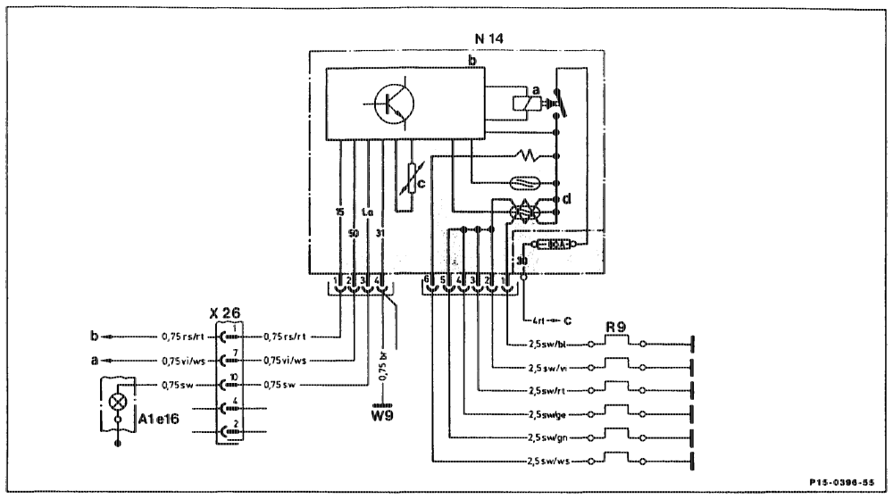
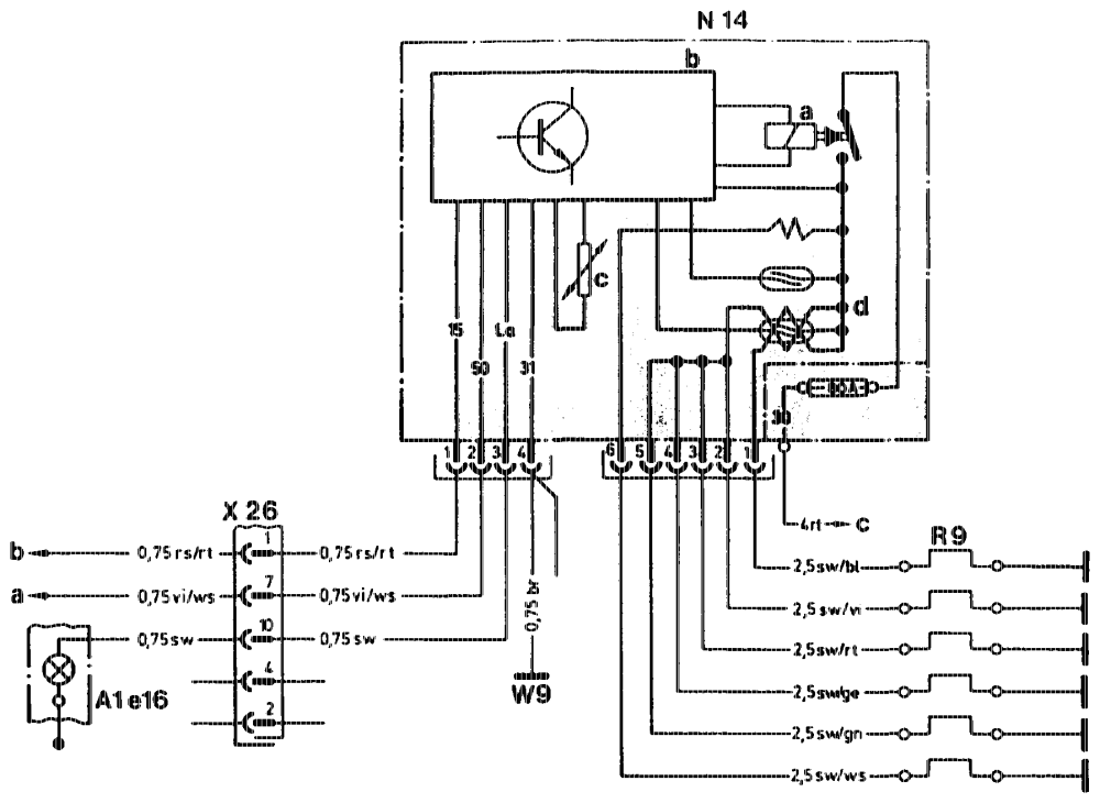
Wiring Diagram Engine 603.96 except G> 1988, Models 124, 126 Ale16 Preglow indicator in instrument cluster X26 Plug connector, interior/angine 12-pin N14 Preglow time relay wg Ground, front left (next to lamp unit) a Power relay a X49/1 plug connector, backup light switch b Electronic unit b Fuse 7, terminal 15 (unprotected) c Temperature sensor (NTC resistor) c X4 Terrninal block, terminal 30 (fuse and relay d Reed relay box) “RO Glow plugs
eptinn RA 15.1010-0705/5
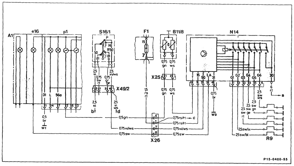
Electric Wiring Diagram Engine 603.96 C> 1988, 603.96 from Model year 1989, Model 124 AM Instrument cluster X25 Plug connector, praglow cable hamess Alet6 Preglow indicator x26 Plug connector, interior/engine Alpi Coolant temperature gauge X4g/2 Plug connector, starter lockout and reversing light B13 Coolant tamperature sensor switch Ft Fuse and relay box a Cable connector X4 (terminal 30) N14 Preglow relay b Glow plug switch S2/2 (terminal 50) Ag Glow plugs c Over-voltage protection relay (jack 3) $16 Starter lockout and reversing light switch d X27 Plug connector, starter cable harness jack 2 Wi Main ground (behind instrument cluster) w9 Ground, front left (next to light unit)
agian = RA 15.1010-0705/6
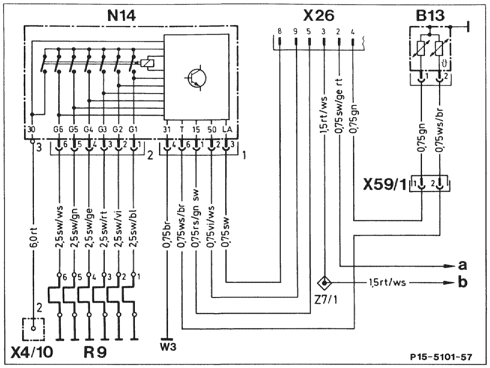
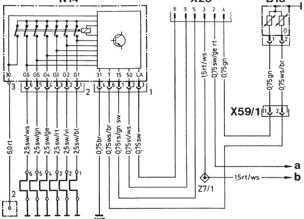
Wiring Diagram Engine 603.971 GA) Model Year 1992, Model 140 B13 Coolant gauge temperature sensor a Relay, key-operated engine stop, pin 4 N14 Preglow time relay b Relay, key-operated engine stop, pin 3 RQ Glow plugs W3 Ground, front left wheelhouse X4/10 Terminal block, terminal 30 x26 Plug connection, interior/engine X59/1 Plug connection, engine fan/coolant temperature sensor 27M Connector sleeve, terminal 30
apttinyy ~=RA 15.1010-0705/7
apie = RA 15.1010-0705/8
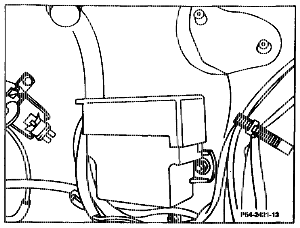
Location of preglow time relay The preglow time relay is housed in the engine compartment on the left wheelhouse. The electrical connections are accessible after removing the protective cap. On Model 140 the preglow time relay must be taken out in order to be able to remove the protective cap.
Shown on Model 201
Functions of Preglow Time Relay The preglow time relay has the following functions: ® Switching on the glow current ® Indicating readiness to start © Safety cutout @ Fault indication
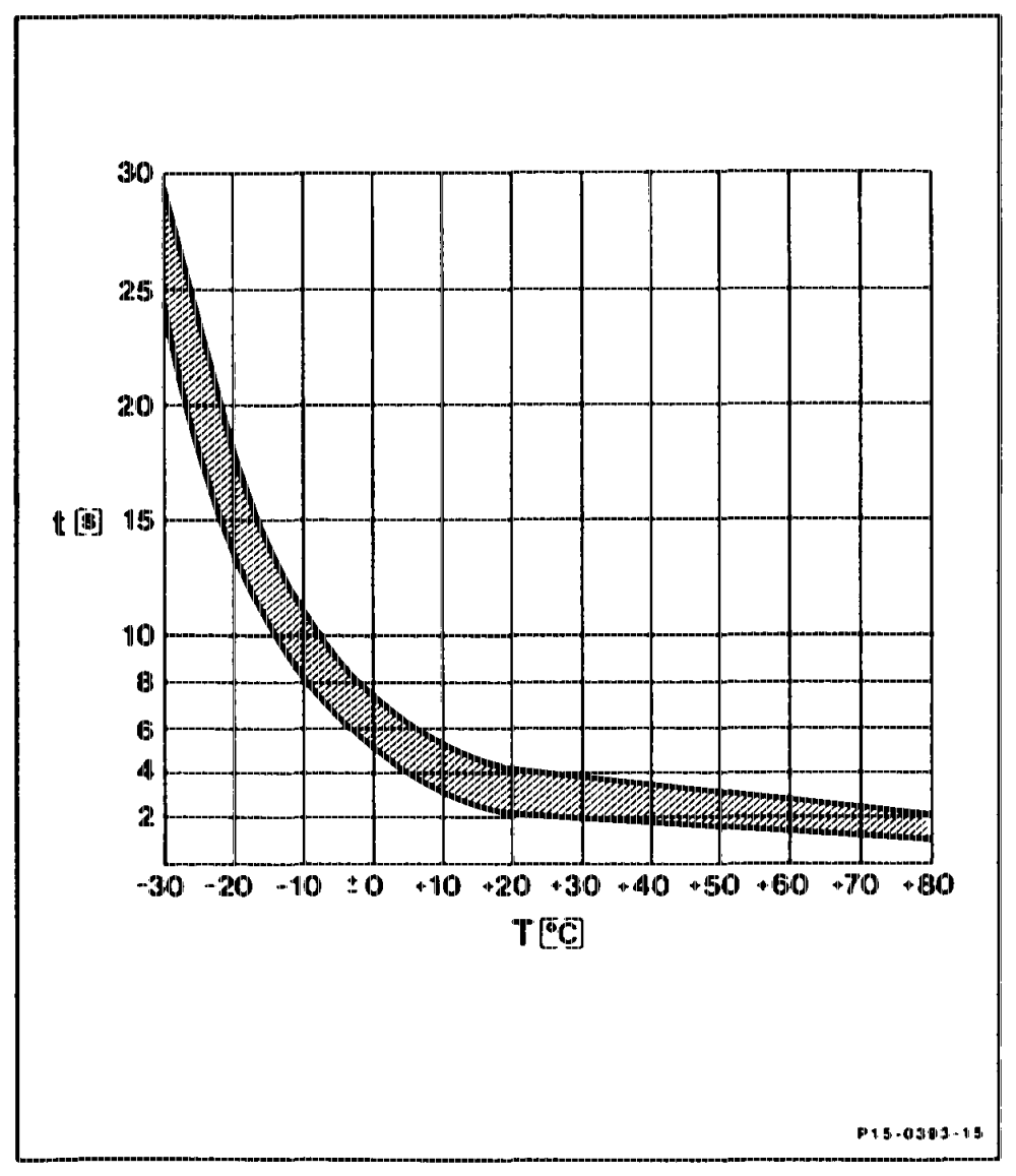
Preglow without Afterglow Model 124 Engine 603.96 Except > 1988 T Ambient temperature of preglow time relay in °C t Preglow time in seconds
utihin =RA 15.1010-0705/9
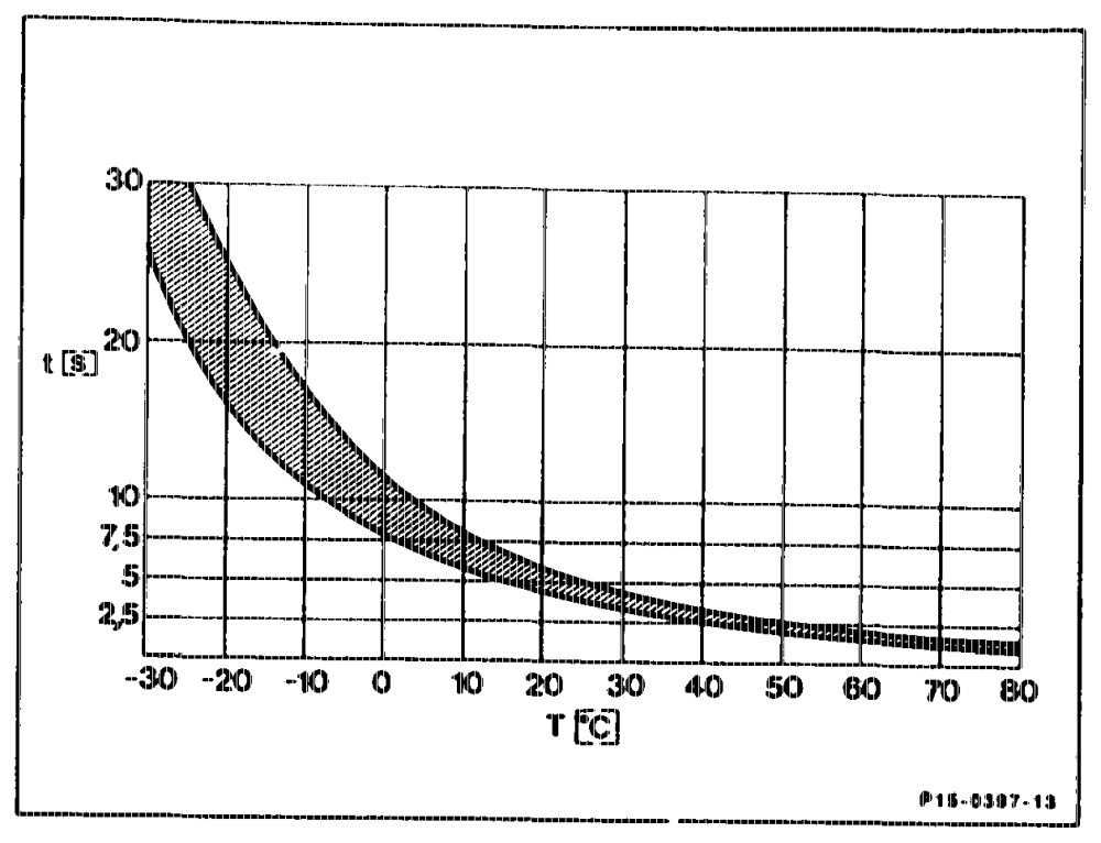
Preglow with Afterglow
Preglow Time T Coolant temperature in °C t Preglow time in seconds
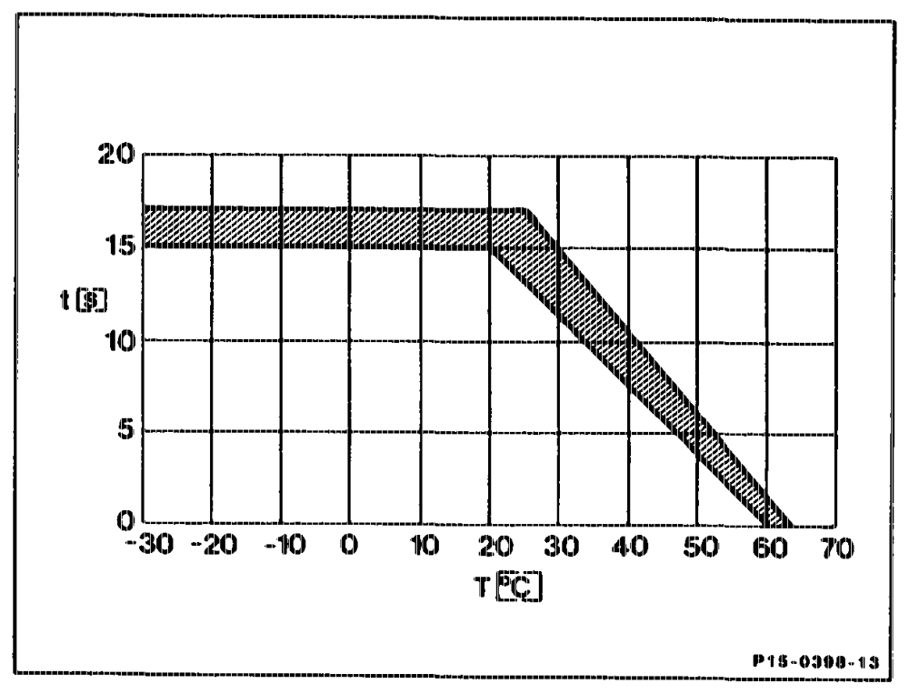
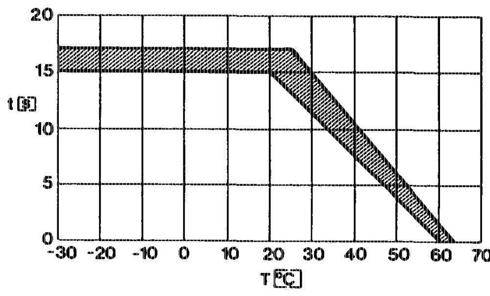
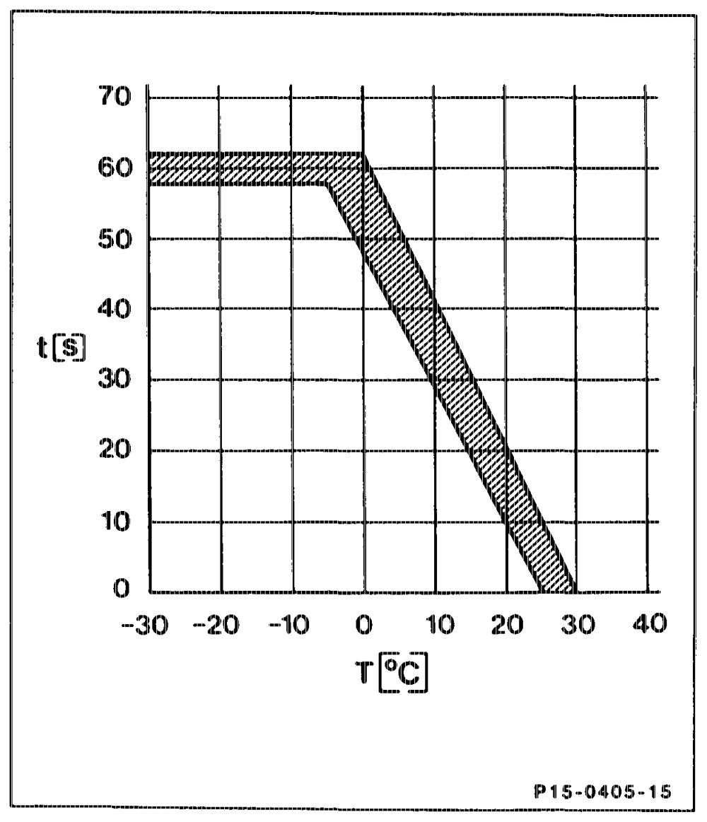
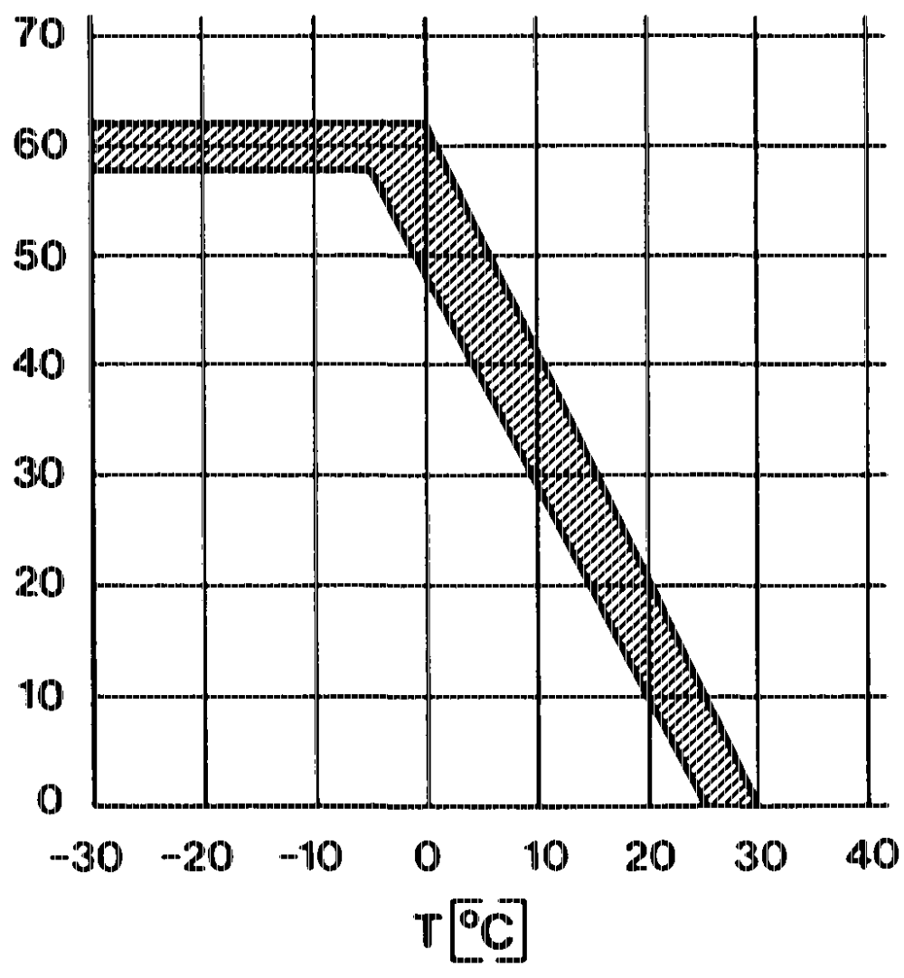
Afterglow Time To improve warming-up properties, the glow plugs continue to glow when the engine is running dependent on the coolant temperature. a) Version: Model 124 Engine 603.96 eS 1988, Model 201 Engine 602.961 Model Year 1988
T Coolant temperature in °C t Afterglow time in seconds Afterglow time up to max. 17.5 $ (refer to diagram)
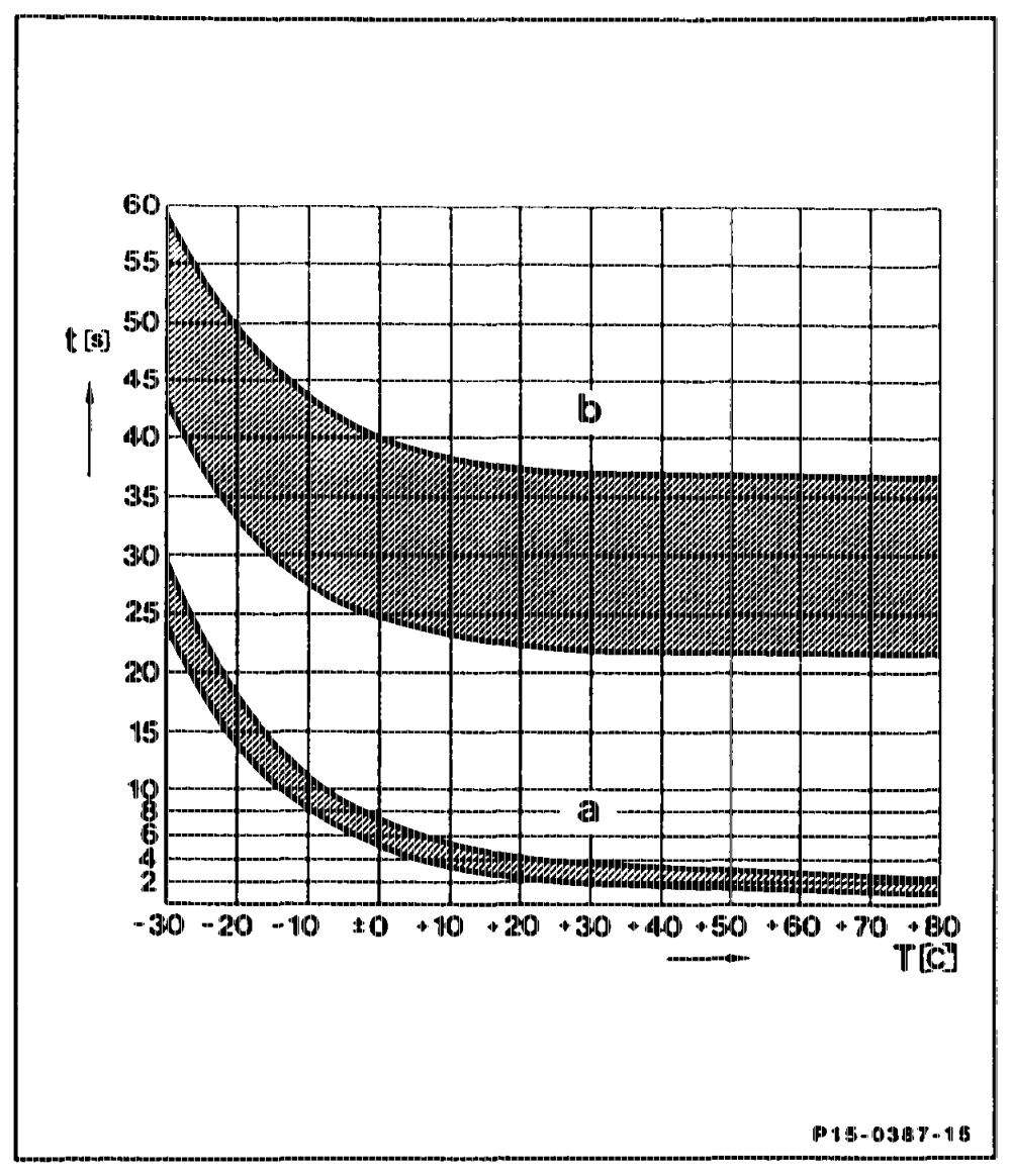
b) Version: Models 124, 201 Engines 602.961/962, Madel 124 Engine 603.96 from Model Year 1989
T Coolant temperature in °C t Afterglow time in seconds Afterglow time up to max. 60 s (refer to diagram)
aptiay RA 1§.1010-0705/10
Safety Cutout If the engine is not started within 20–25 seconds after the readiness to start indication being given, the glow current is interrupted by the safety cutout. If the engine is then started, the glow system is switched on again for the duration of the starting operation. The duration of safety cutout is not fixed. It results from the time up to readiness to start (preglow indicator lamp going out) plus 20–35 seconds.
b Safety cutout
Actuating the Glow Current When the key is moved into position ”2” (preglow, drive), the preglow time relay is switched on (voltage to terminal 15). The preglow time relay closes the circuit from terminal 30 (positive) to the glow plugs (R9).
If the key is turned into position „3” (start), the preglow time relay remains activated and remains picked up through terminal 50. The glow process is continued until the key is turned back to position „2”.
Readiness to Start Indication
a) Model 124 Engine 603.96 except Co 1988 When the glow system is switched on, the preglow indicator lamp in the instrument cluster lights up. The glow duration is determined by a temperature sensor installed in the pregiow time relay. Once the required glow time has been reached, depending on the ambient temperature of the preglow time relay, the preglow indicator lamp goes out, thus indicating that the engine is ready for starting.
aptiinn = RA 15.1010-0705/11
Fault Indication Model 201 Engine 602.961, Model 124 Engine 602.962, Engine 603 Models 124, 201 Engine 602.961, 602.962, 603.96 (> 1988 603.96 as of 1989 Effective 1989 When the glow system is switched on, the A fault in the preglow systern is indicated by the preglow indicator lamp in the instrument cluster preglow indicator lamp failing to light up when lights up. The glow duration is determined by the key is turned into position ”2”. In addition, the temperature sensor in the coolant. Once the the preglow indicator lights up for approx. required glow time has been reached, the 1 minute when the engine is running. preglow time relay switches off the preglow indicator larnp, indicating that the engine is The following faults are detected: ready for starting. ® Interrupt in the cable to connection terminal 30. ® Preglow time relay faulty. Fault Indication ® Interrupt in one or several cables to the Model 124 Engine 603.96 Except C) 1988 glow plugs. ® {nterrupt in one or several glow plugs. A fault in the preglow system is indicated by the ® Short-circuit at one or several glow plugs or preglow indicator lamp failing to light up when the key is moved into position „2”. in the cables.
The following faults are detected: © Interrupt in the cable to connection terminal 30. © 80 ampere fuse faulty. ® Fault in power relay of preglow time relay. ® Interrupt in one or several cables to the glow plugs. ® Interrupt in one or several glow plugs.
apis = RA 15.1010-0705/12