Operation no. of operation texts and work units or standard texts
WIS 07.1-8244
8244 07.1~
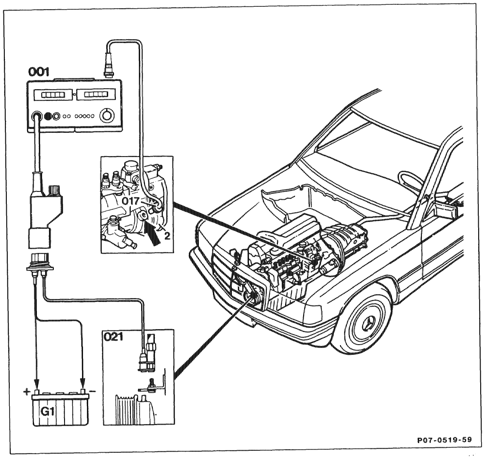
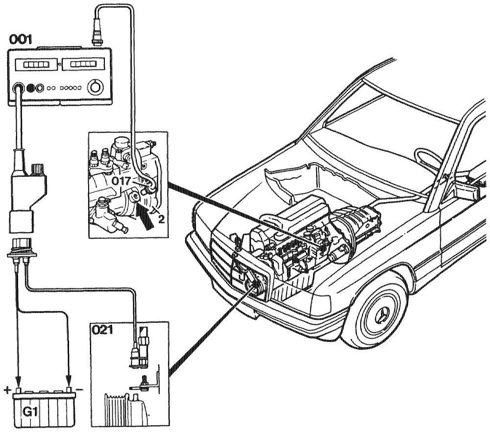
Operation no. of operation texts and work units or standard texts and flat rates: 07-8244 or 07-8245
Screw plug (arrow) on governor housing (2) …. unscrew, tightening torque 30–35 Nm. g ( g g\ Q 9 Testers (001, 017, 021) ……– wee aee see connect. Engine ….. Dee w eww eee ee ete e eens run at idling speed, read off Ri value, adjust start of delivery if necessary (07-8300, section „B”).
eotthiyn = RA 07.1.1051-8244/1
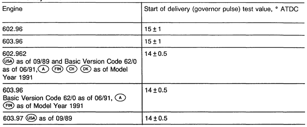
Test and adjustment data
Commercially avallable tools and testers Designation @. g. make, order no.
Used without adapter
Digital testers Bosch, ETD 019.002 Sun, DIT 9100 AVL, Diesel-Tester 873
Used with adapter
Digital tester Bosch, MOT 001.03
autahipn = RA 07.1.1051-8244/2
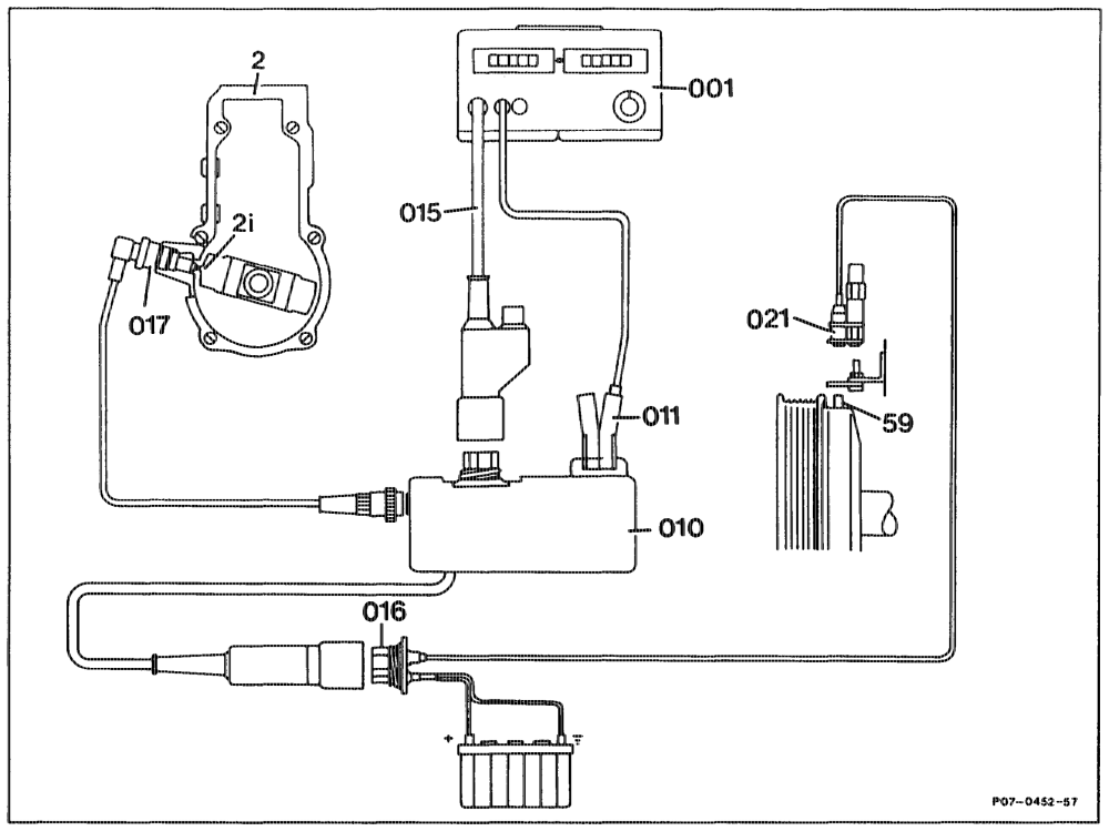
Connection diagram for available testers with adapter 001 Digital tester 017 RI generator 010 Adapter 021 TDC pulse generator o11 Trigger clamp 2 Govemor 015 Test cable with connector 2i RI generator pin 016 Diagnostic socket 59 TDC generator pin
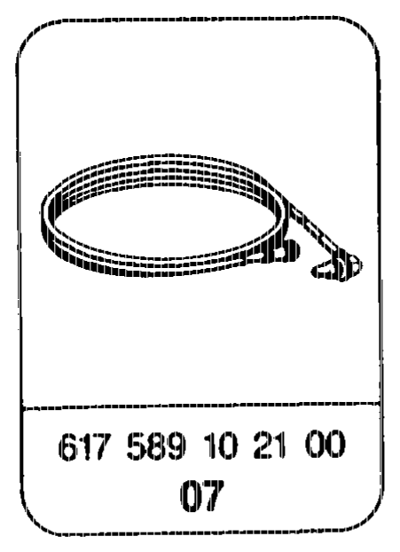
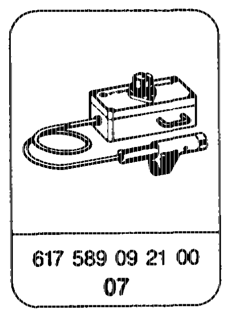
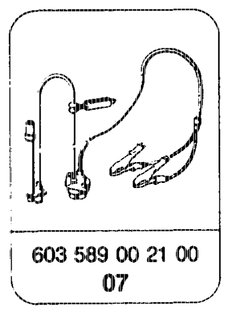
Special tools
otis = RA 07.1.1051-8244/3
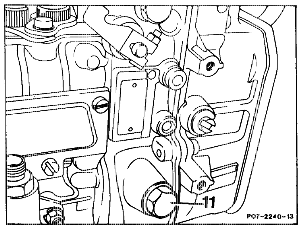
1 Unscrew plug (11) on the governor housing.
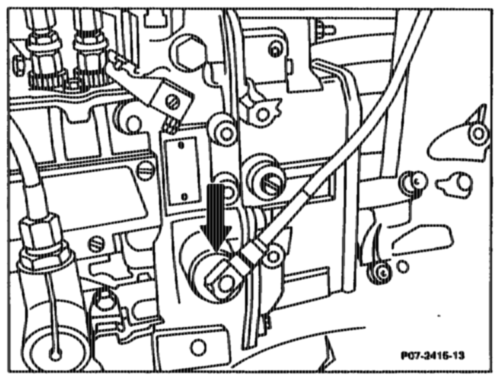
2 Screw in Al generator (017, arrow) at governor (injection pump).
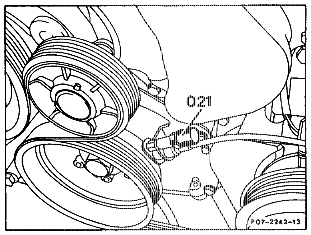
3 Screw in TDC pulse generator (021) at bracket (engine).
«ptm = RA 07.1.1051-8244/4
4 Connect digital tester as shown in connection diagram.
5 Run engine at idling speed, read off RI value (indirect start of delivery) at the digital tester at idle speed and compare with specification. Adjust start of delivery if necessary (07.1-8300, section ”B”).
6 Switch off engine.
7 Disconnect digital tester.
8 Screw in plug at governor. Tightening torque 30-35 Nm.
9 Perform leaktightness check with engine running.
10 Check engine oil level, correct if necessary.
qtthijy =RA 07.1.1051-8244/5