Function of injection system
WIS 07.1-0010
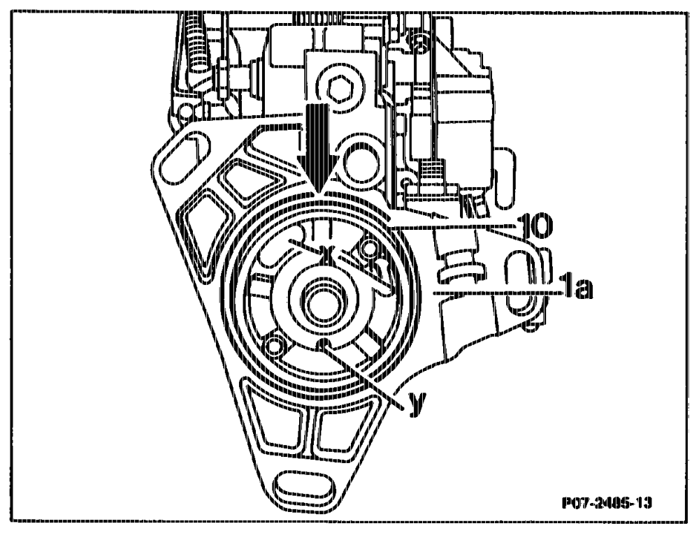
A. Lubrication of injection pump
The injection pump is connected through an oil bore (arrow) to the engine oil circuit. The oil flows back into the crankcase through the annular gap (x) between bearing and housing.
The O-ring (10) on the flange (1a) acts as a seal. The bore (y) serves to relieve the radial seal of oil.
atts = RA 07.1.1032-0010/1
B. Fuel circuit
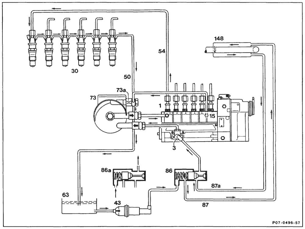
a) Fuel circuit diagram
Restriction orifice in fuel fitter top section Injection pump dia. 0.8 mm Fuel pump Bypass valve with restriction dia. 1.5 mm Fuel thermostat open, position up 15 to + 8 °C, fuel is preheated Injection nozzles Fuel thermostat closed, position as Fuel prefilter 43 from + 25 ° C, fuel is no longer preheated. Leak oil hose Inlet line — cold fuel Injection line, No. 1 cylinder 87 Return line — preheated fuel Fuel tank 63 87a Heater inlet pipe with fuel heat exchanger 73 Fuel fitter top section 148
aptihis = RA 07.1.1032-0010/2
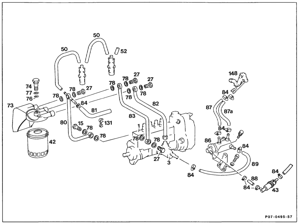
b) Low-pressure side
1 Injection pump 80 Retum line
3 Fuel pump 81 Fuel hose retum line
15 Bypass valve with restriction dia. 1.5 mm 82 Fuel filter inlet line
27 Hollow screw 83 Injection pump inlet line
42 Fuel filter 84 Hose clip
43 Fuel prefitter 86 Fuel thermostat
50 Leak oil hose 87 Fuel heat exchanger inlet line §2 Plug 87a Fuel heat exchanger retum line
73 Fuel filter top section 88 Fuel thermostat inlet line
74 Fuel fitter hollow screw 89 Fuel pump suction line
76 O-ring 131 Plastic holder
77 Fuel fitter seal 148 Heater inlet pipe with fuel heat exchanger.
78 Seal
apts = RA 07.1.1032-0010/3
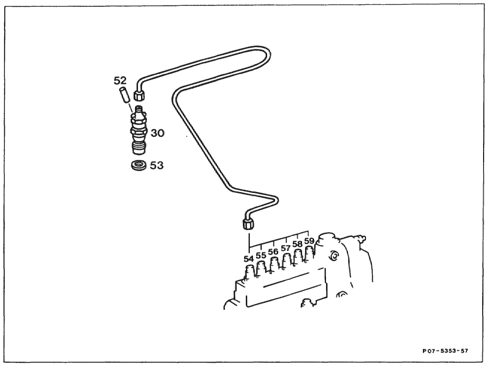
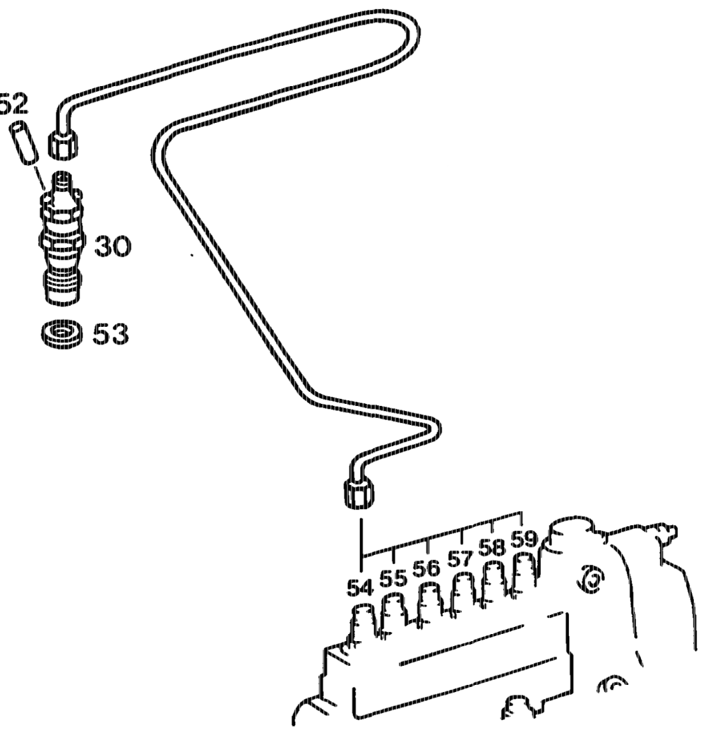
c) High-pressure side
30 Injection nozzle complete 56 Injection tine 3
52 Plug 57 injection fine 4
53 Nozzle shir 58 Injection line 5
54 Injection line 1 59 Injection line 6
55 Injection line 2
Note Injection lines of cylinders 2–6 are not illustrated. Bracket for injection lines of cylinders 5–6 as bracket of cylinder 4.
qptihiyn = RA 07.1.1032-0010/4
Cc. Fuel prefilter (43)
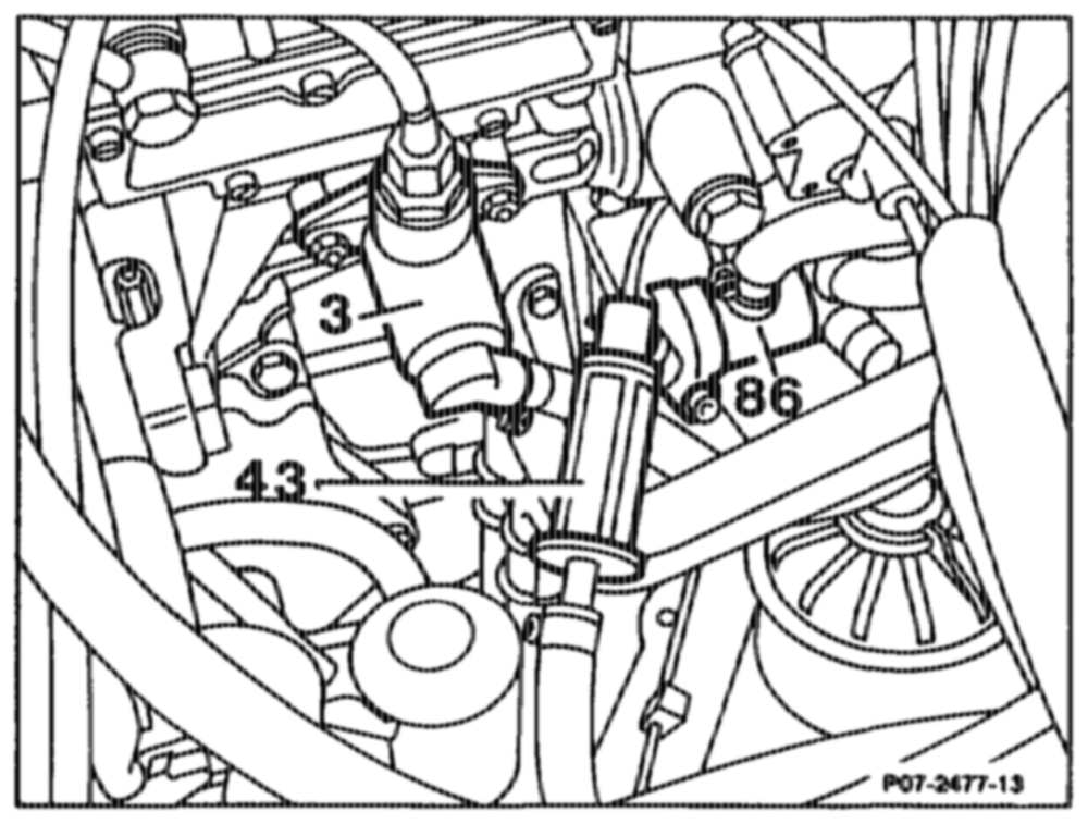
Installed in the suction line upstream of the fuel pump (3). The filter housing is made of a transparent plastic. The mesh size is 600 pm (0.6 mm).
D. Fuel filter (42)
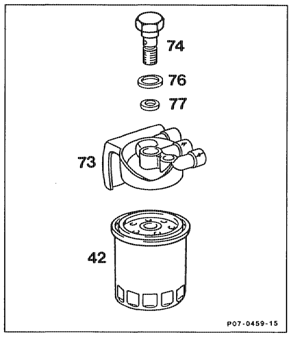
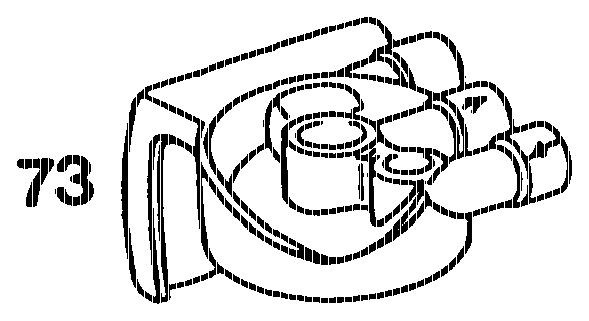
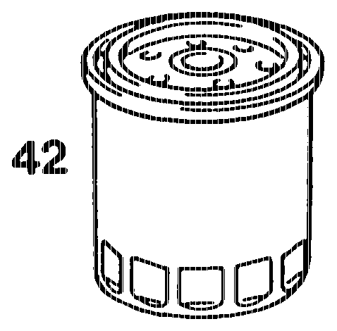
Installed in the pressure line between fuel pump and injection pump. The paper filter element is integrated in a metal housing. The paper element has an average pore size of 6–10 ym (0.006~-0.01 mm).
42 ~~ ‘Fitter 73 ~~ “Fuel filter top section 74 ~=Bolt 76 = O-ring 77 Seal (alu)
Note When the engine is started, the fuel system is bled automatically as result of the greater delivery of the fuel pump and the restrictions in the filter top sections as well as at the injection pump.
ute =§=RA 07.1.1032-0010/5
E. Fuel preheater (148)
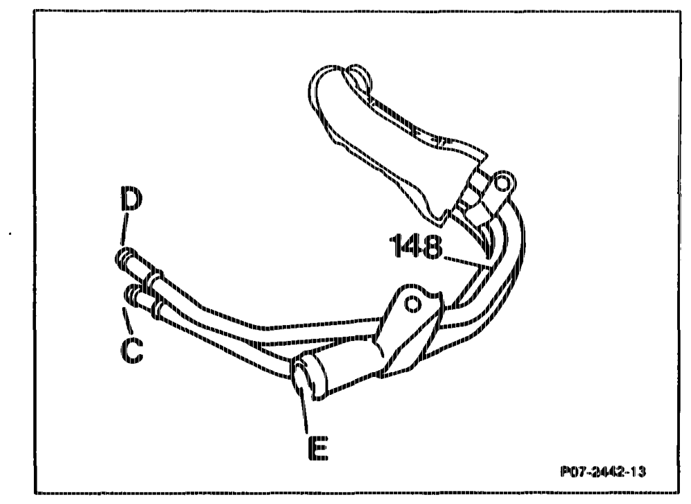
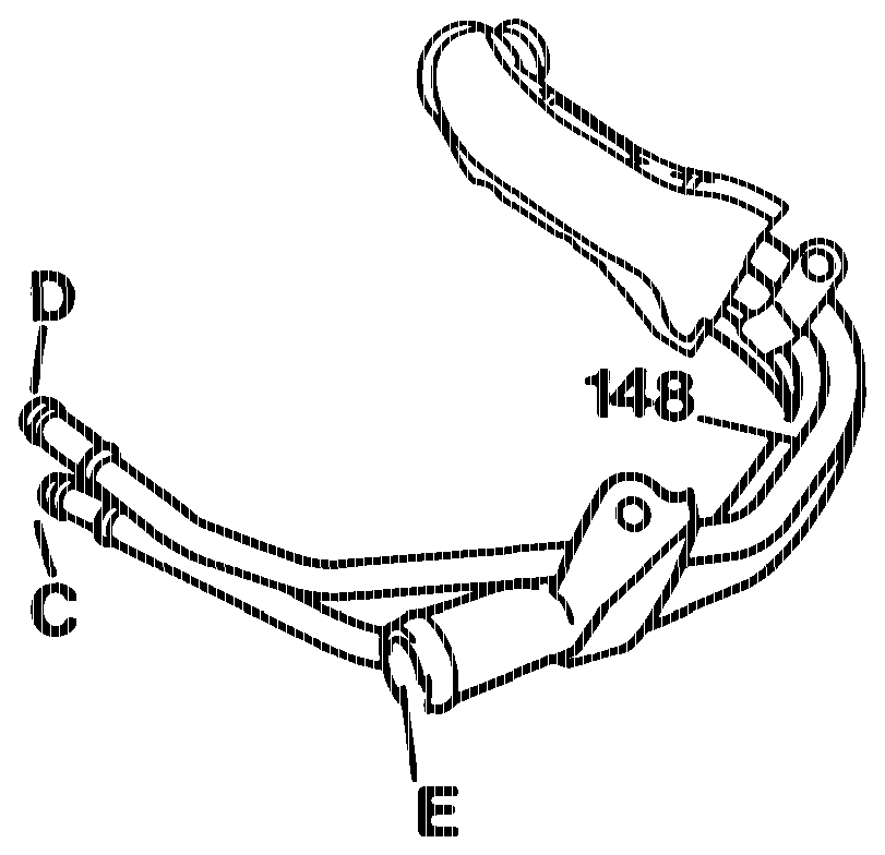
A heat exchanger (148) is installed in the inlet line of the heater to preheat the fuel.
Heat exchanger C Inlet line D_ Retum line E Heater inlet 148 Heat exchanger
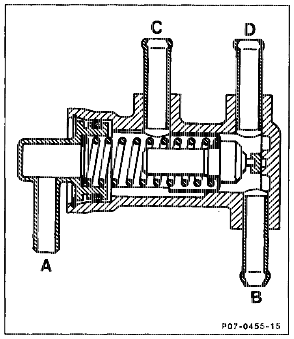
Function Full preheating up to + 8 °C fuel temperature; the required fuel is drawn in through the heat exchanger by the fuel pump. From + 8 °C up to + 25 °C mixed operation; the required fuel flows partially through the heat exchanger. Above + 25 °C the heat exchanger is bypassed by the thermostat; the fuel is drawn in directly by the fuel pump. Fuel preheating ensures troublefree operation with winter-grade diesel fuel as a rule down to approx. -25 °C ambient temperature.
Fuel thermostat A Inlet line from fuel tank 8 Suction line to fuel purnp C Inlet line to heat exchanger D Return line trom heat exchanger
agthim = RA 07.1.1032-0010/6
F. Fuel pump (3)
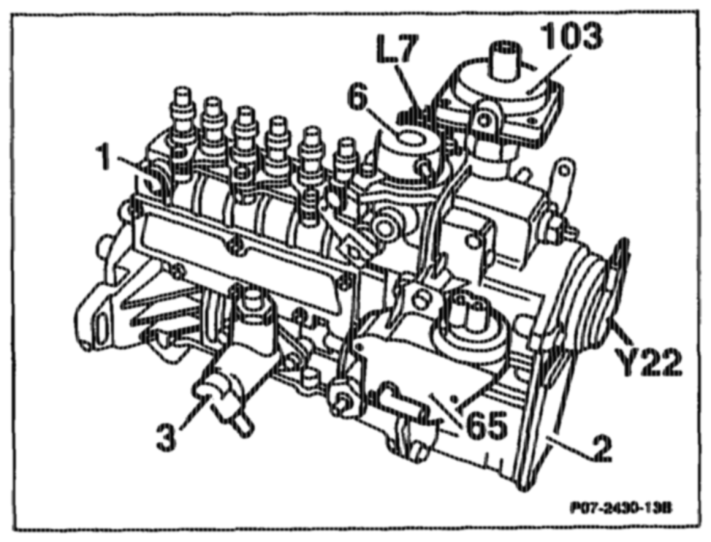
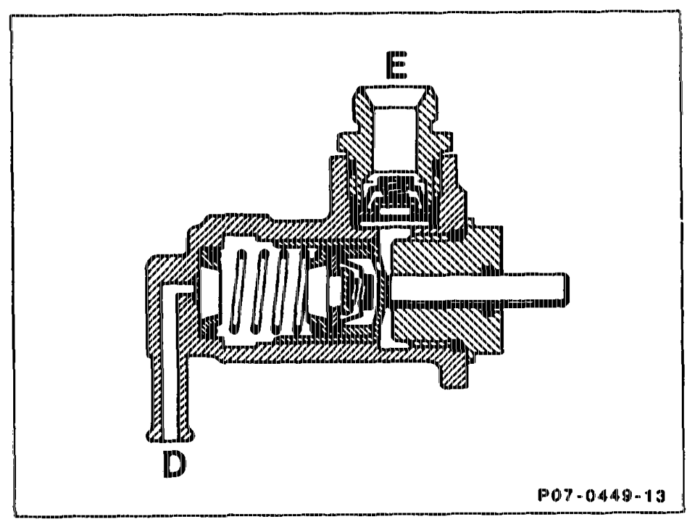
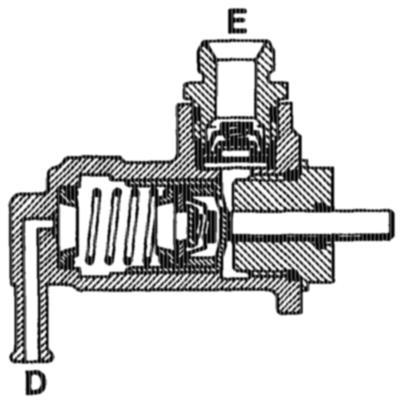
As a result of the high delivery of the fuel pump, the fuel system is self-bleeding, which makes it possible to eliminate the hand priming pump. Delivery > 150 cm?/30 s, at starting speed > 150/min, measured in fuel retum line.
E Pressure side D Suction side
aptahiy = RA 07.1.1032-0010/7
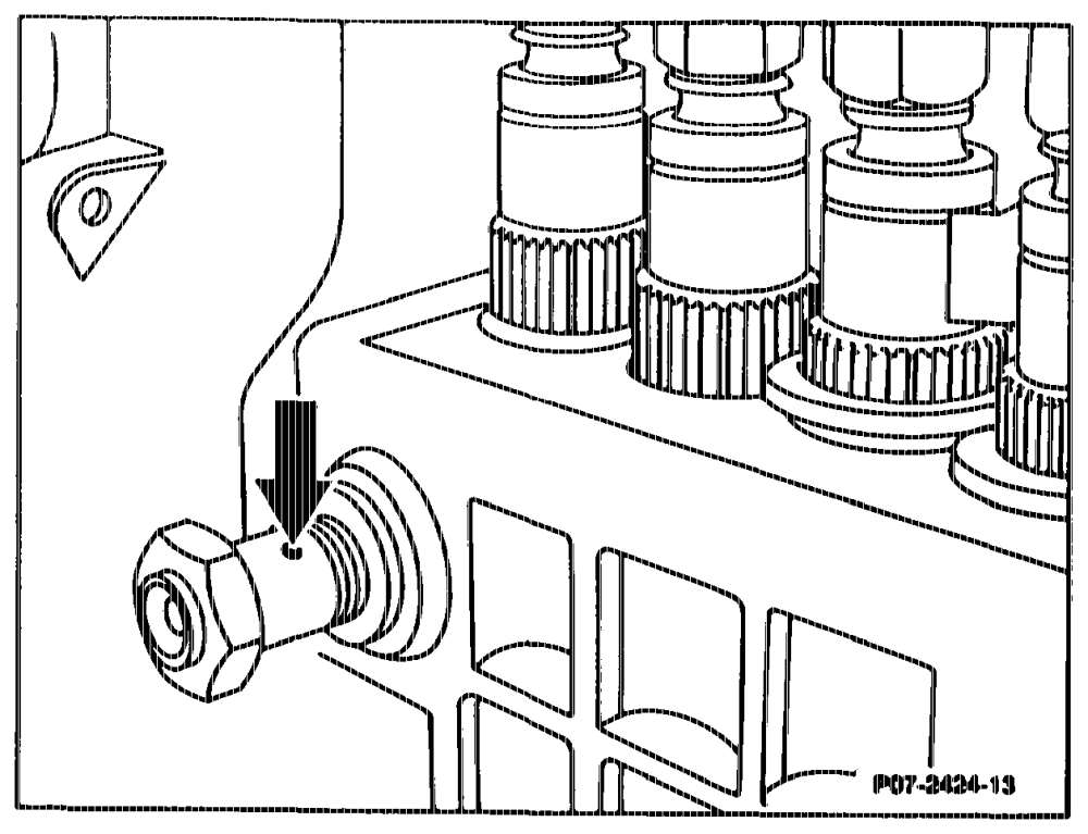
A restriction in the bypass valve at the injection pump is required for bleeding the injection pump.
Bypass valve with restriction dia. 1.5 mm (arrow).
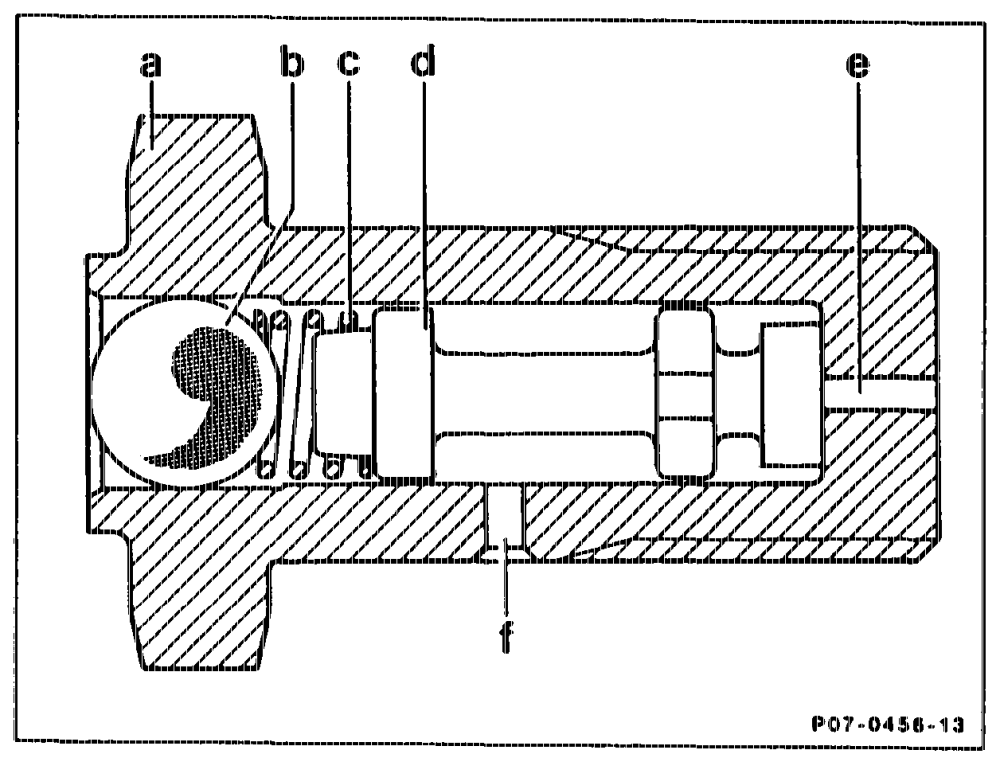
The bypass valve prevents unfilte ad fuel flowing along the return line into the injec ion pump if the inlet line is clogged (@. g. filter).
Restriction with bypass valve a _ Housing b Ball c Spring d= Slide e Inlet Restriction orifice dia. 1.5 mm
G. Start of delivery adjus
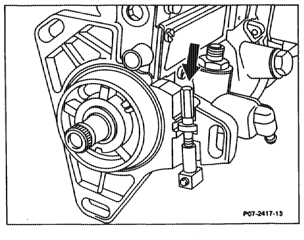
An adjusting device (arrow) is attached to the injection pump flange in order to be able to adjust the start of delivery when the engine is running.
ptthiyn =RA 07.1.1032-0010/8
H. Reverse flow damping valve in delivery valve holder
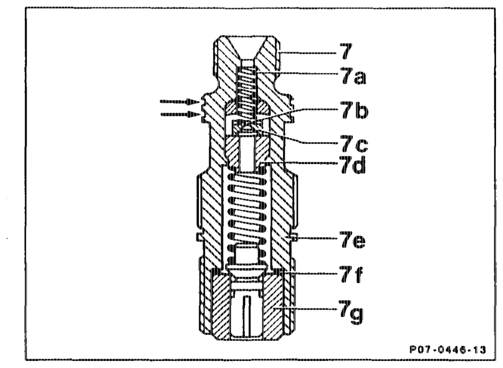
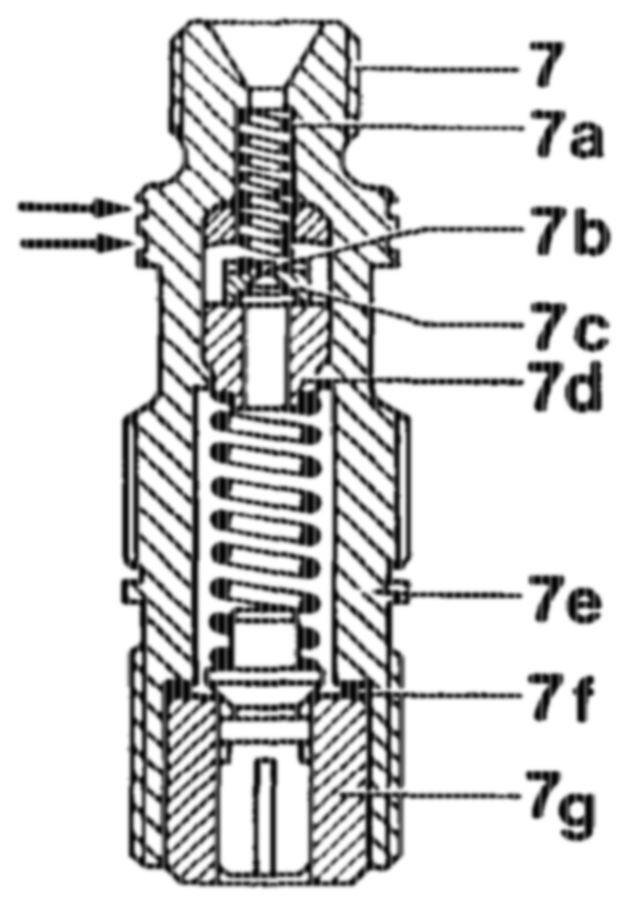
Reverse flow damping valves (7b) are installed in the delivery valve holders (7) of the injection pump in order to reduce the hydrocarbon portion in the exhaust gas. They prevent any afterspraying of the injection nozzles. Two annular grooves act as identification marks on the delivery valve holder (7) (arrows). The raverse flow damping valve (7b) is a disc valve (7c) opening in the direction of the injection nozzle with a restriction orifice of 0.5 mm dia. The valve seat (7d) is riveted into the delivery valve holder.
I. Injection timer
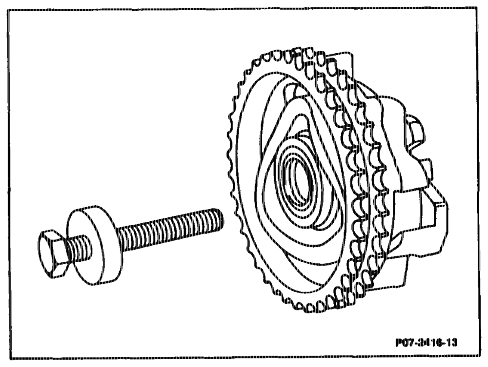
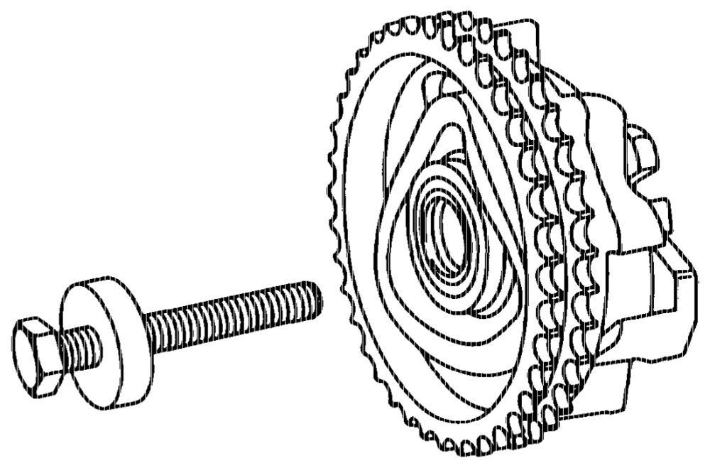
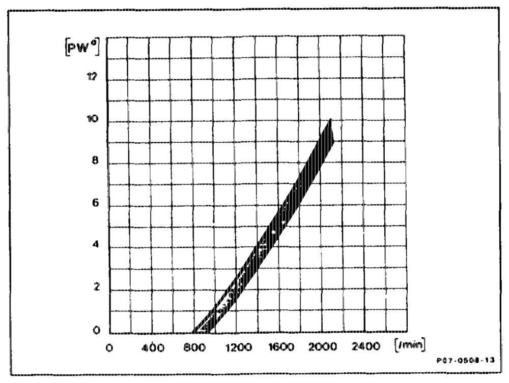
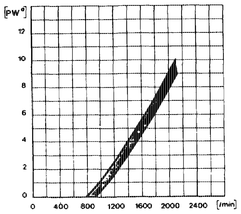
The injection timer is mounted on the injection pump shaft and is attached with a central bolt having a lefthand thread.
Injection timer adjustment curve n = rpm af injection pump Pwe == adjustment angle of injection pump
whitey RA 07.1.1032-0010/9
J. RSF Governor
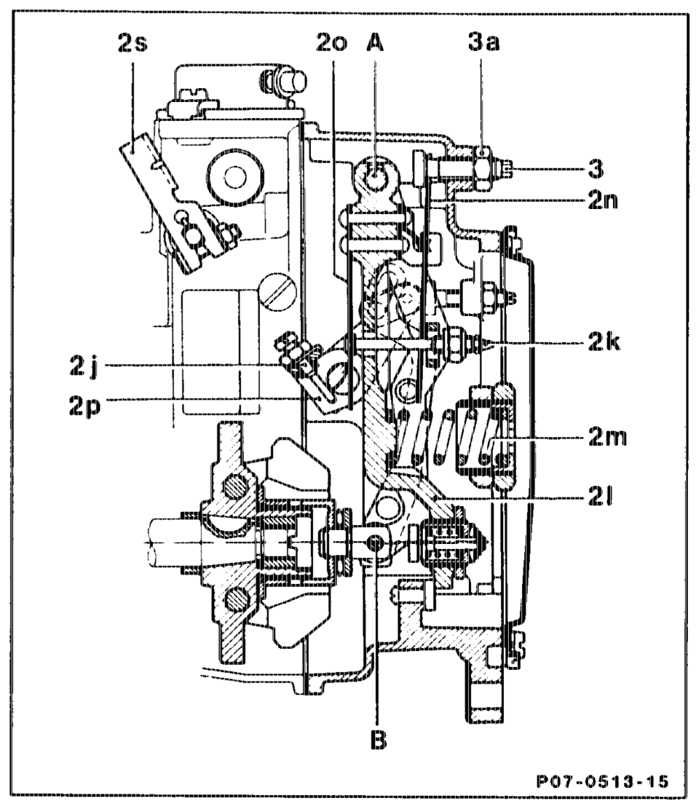
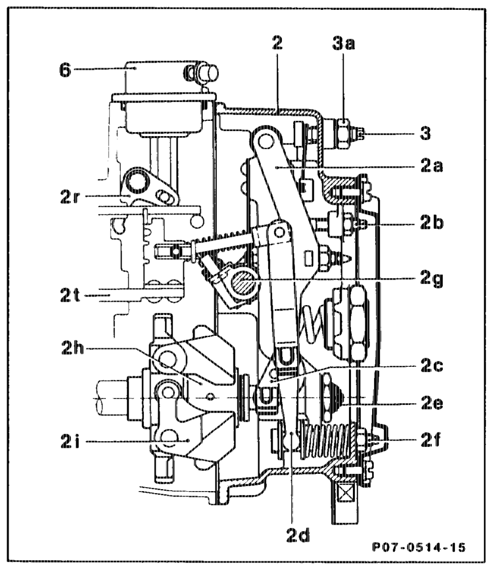
a) Design and operating principle The governor is a minimum/maximurn speed governor, the governor spring of which (2m) is sized and set in such way that it does not govern in the part load range, with the exception of torque control (refer to „Control when starting and at full load”). In the part load and full load range, the control rod (2t) of the injection pump is operated only from the accelerator pedal, which is connected through the accelerator control linkage to the control lever (2g) of the governor. The idling spring (2n) is pretensioned and the idle speed set by the adjusting screw (3).
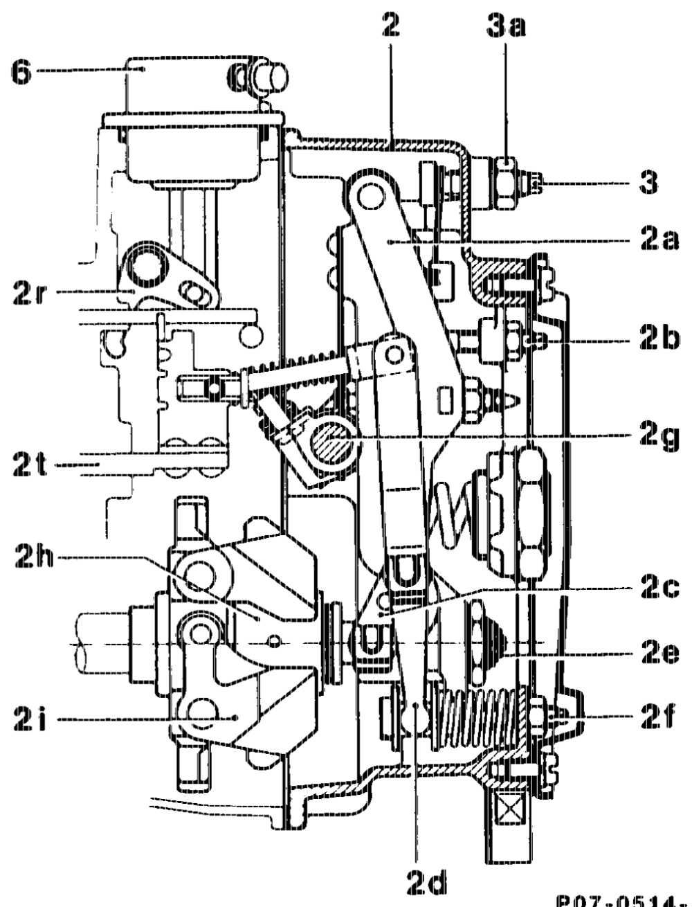
2 Govemor 2a Guide lever 2b Stop screw for idle quantity 2c Relay lever 2d) Fulcrum lever 2e Spring retainer (torque control) 2t Full load adjusting screw 2g Control lever 2h_ Sliding sleeve
2 Flyweights (pump-governor group) 2) Idling audliary spring ~ cutoff 2k Adjusting screw for idling auxiliary spring (idling stabiliser)
21 Tensioning lever 2m Govemor spring 2n_— Idling spring
20 Idling auxiliary spring (idling stabiliser) 2p Stoering arm 2r Stop lever 2s Emergency stop lever 2t Control rod 3. Adjusting screw for idle speed 3a Locking nut
6 Vacuum unit (stop)
otis = RA 07.1.1032-0010/10
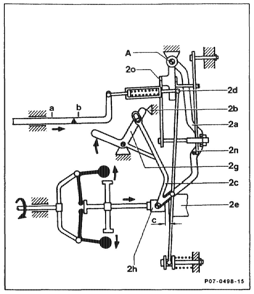
b) Control when idling Control lever (2g) is resting against the idle stop screw (2b). As the engine speed increases, the sliding sleeve (2h) passes through the idling state. Guide lever (2a) swivels around the pivot point „A” and thus operates against the idling spring (2n). At a certain engine speed, the guide lever (2a) moves against the adjusting nut of the idling auxiliary spring (20). The movement of the sliding sleeve (2h) is transmitted through the relay lever (2c) and fulcrum (2d) in the same direction to the control rod of the injection pump. After passing through the idling stage, the sliding sleeve (2h) moves against the spring retainer (2e). If the engine speed increases further (e.g. deceleration), from a certain engine speed on, first of all the spring retainer (2e) and then the governor spring (2m) is over-compressed. The control rod is thus brought into the „stop Start Stop position” (deceleration fuel cutoff). Idling stage
egtinn FLA O7.1.1032-0010/11
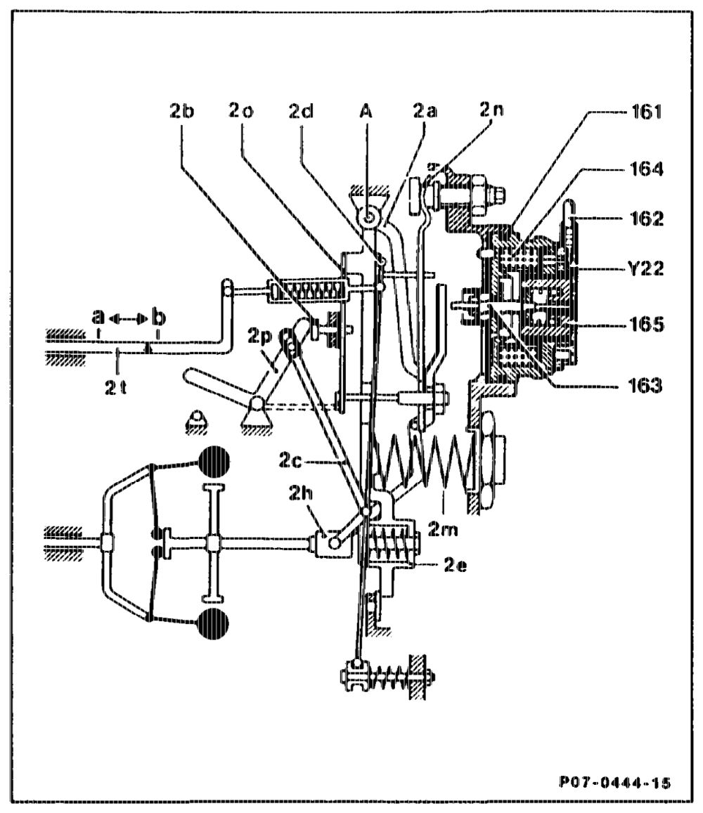
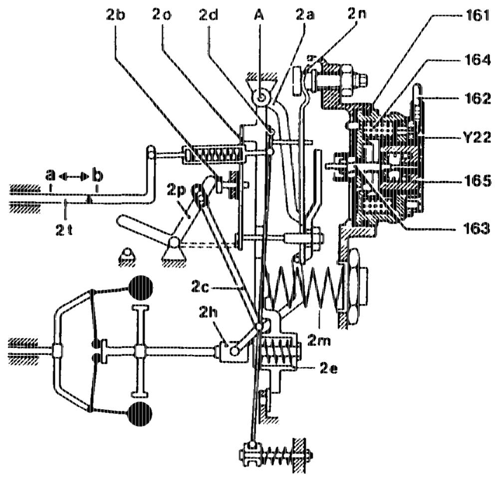
c) Control with actuator The lift rod (163) is resting against the guide lever (2a). The actuator (Y22) is fed by the control unit (electronic idle speed control) with a clocked D.C. voltage in the frequency range of approx. 50 Hz. If engine speed drops (e.g. drive position engaged or power steering turned to full lock), the actuator is energized with a higher voltage. This causes the lift rod (163) to press against the guide lever (2a) and the control rod (2t) moves in the direction „a” increased quantity. As soon as the engine speed increases, the voltage is reduced and the control rod (2t) moves in the direction of „b” reduced quantity.
161 Electrical connection 162 Lift rod 163 Solenoid coil 164
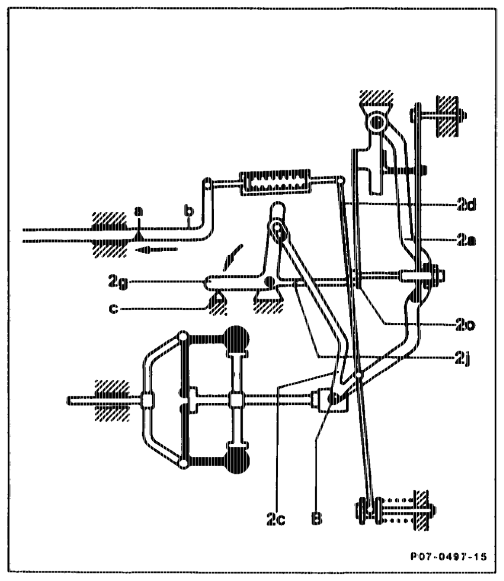
d) Start position If the control lever (2g) is moved against the full load stop (c) (fixed stop on governor housing) when the engine is not running, the relay lever (2c) moves around the pivot point „B” and moves the fulcrum lever (2d) with it in the direction of Start. When the control lever is in the full load position (2g “Full throttle”) the idling auxiliary spring (20 idling stabiliser) is pressed away from the guide lever by the cutoff idling auxiliary spring (2j). This enables a more rajfid cutoff from the start position of the governor.
apts ~=RA 07.1,1032-0010/12
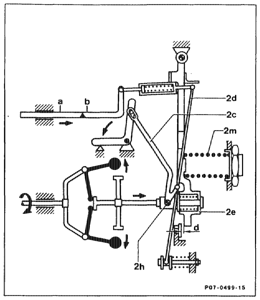
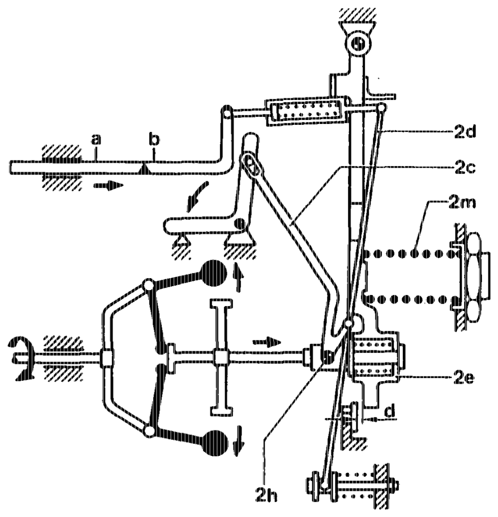
e) Full load speed regulation/adaption After passing through the idling stage (c) (refer to ill. of control when idling) the governor sleeve (2h) moves against the spring retainer (2e). This causes the relay lever (2c) and fulcrum lever (2d) to move the control rod of the injection pump into the full load position. When a certain engine speed is reached, the spring retainer (2e) is over-compressed by a certain distance (d) (adaption).
lf the engine speed continues to rise, the force of the flyweights is sufficient to over-compress the governor spring (2m) (full load speed regulation). The start of cutoff depends on the preload of the governor spring (2m).
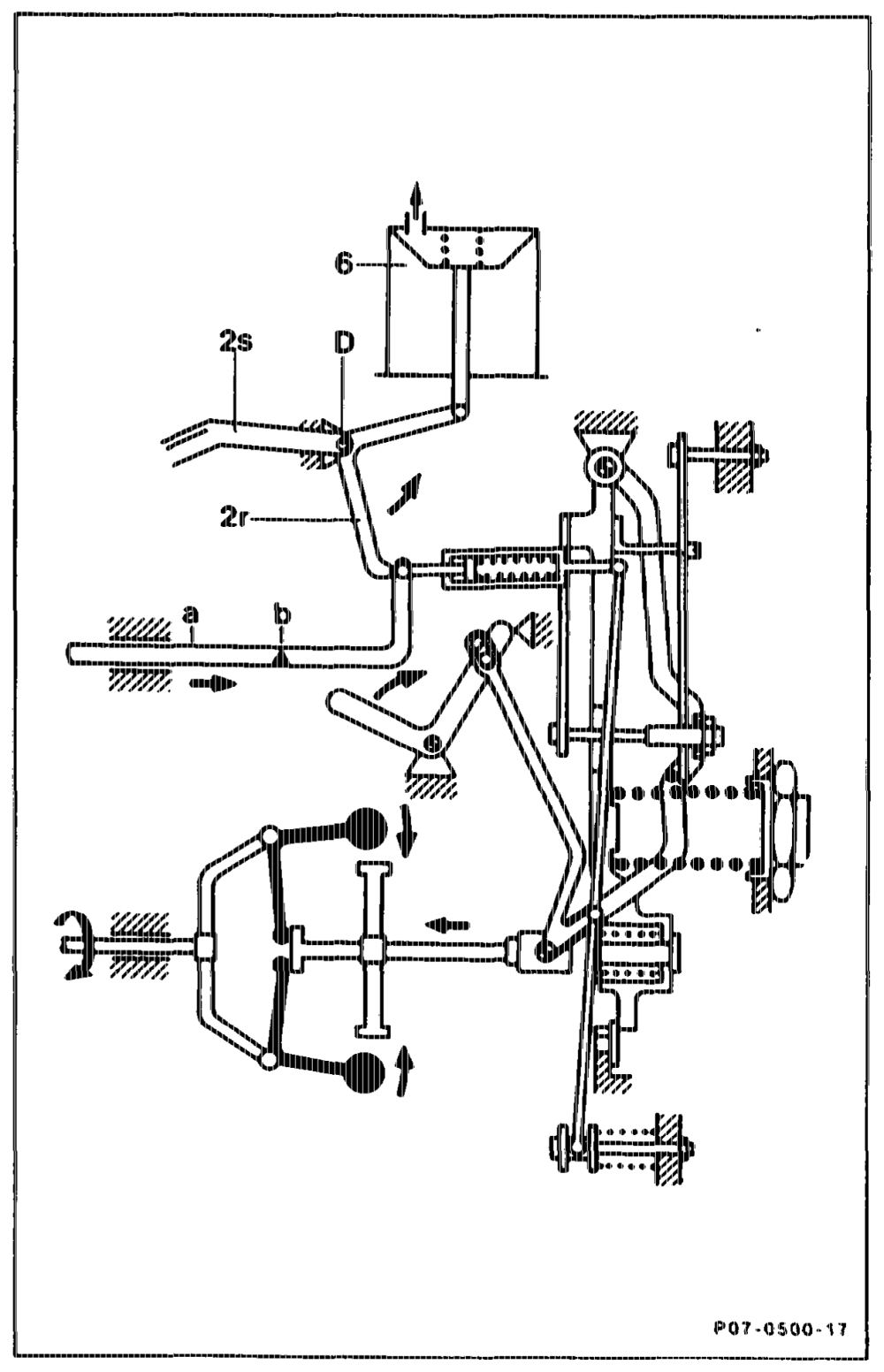
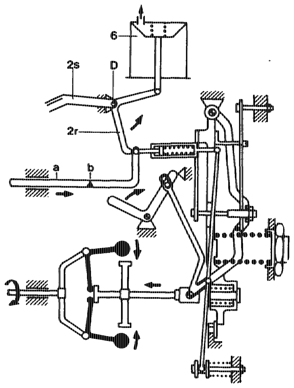
f) Engine stop The vacuum unit (6) is pressurized with vacuum from the vacuum pump through the glow start switch of the vehicle. This causes the diaphragm of the vacuum unit to move against the compression spring. The vacuum unit (6) is connected to a stop lever (2r), which swivels about the pivot point „D”, pulling the control rod of the injection pump into „Stop” position. This causes the deflecting spring of the fulcrum lever to be overcompressed. The control rod can be pulled into the „Stop” position from the outer side of the governor in the same way by means of the emergency stop lever (2s).
apie = RA 07.1.1032-0010/13
K. Intake manifold pressure compensator (ALDA)
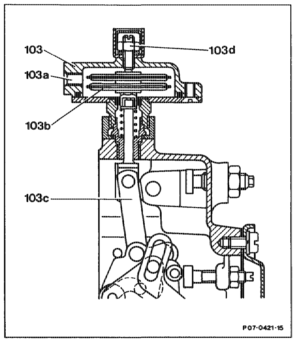
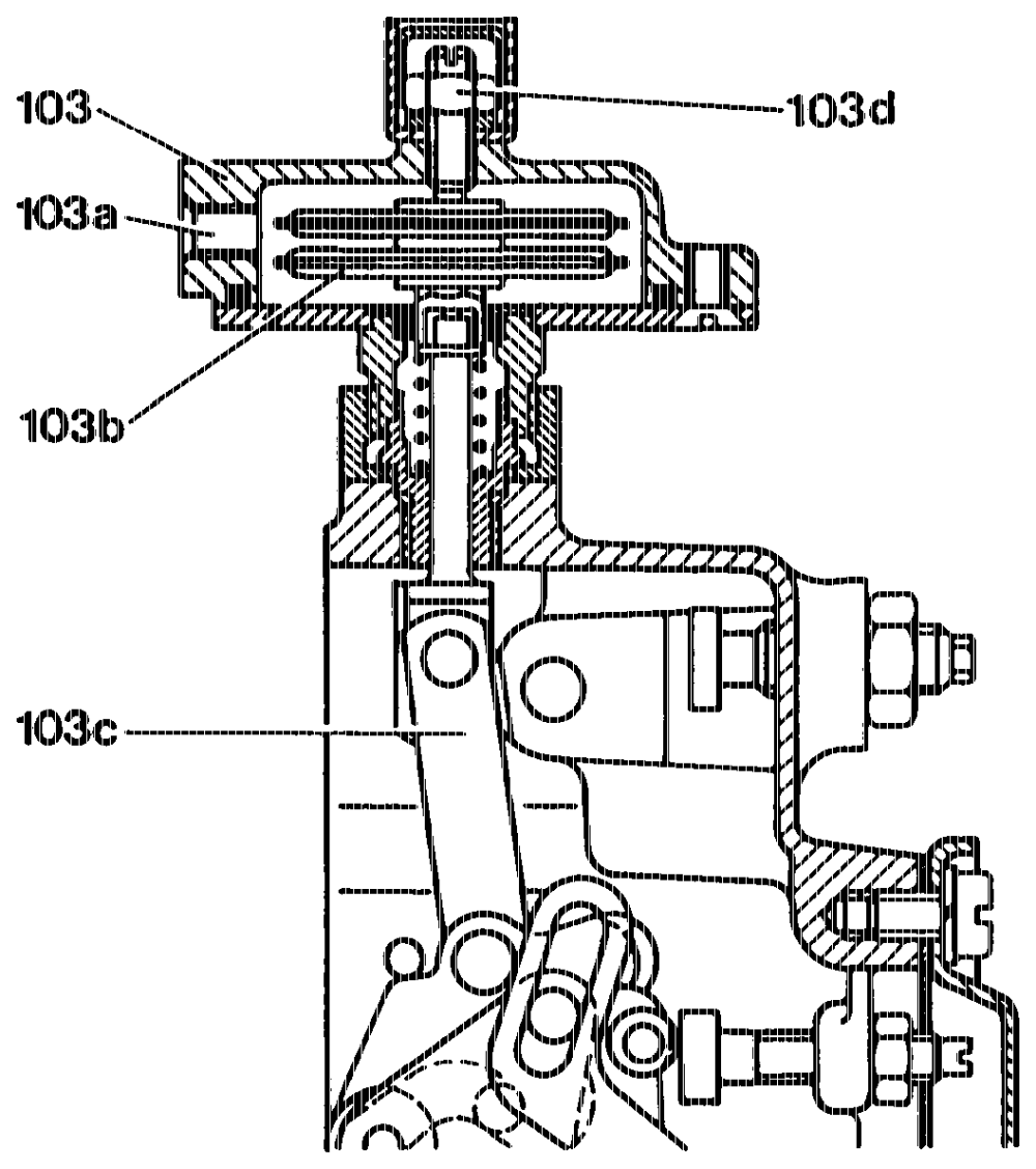
The intake manifold pressure compensator (ALDA device) comprises a housing (103) with barometer unit (103b). The absolute pressure can act on the barometer units by means of a port (103a) to the charge air pipe of the engine, and the barometer units thus react to every pressure change with a change of length. All movements are transmitted to the compound lever of the governor and to the control rod. As the absolute pressure drops, the barometer units expand. The correction linkage (103c) of the units is pressed downwards and acts on the compound lever to move the control rod in the direction of „reduced quantity”. As the absolute pressure rises, caused by a higher air and/or charge pressure, the movement is performed in
the opposite direction ~ i.e. in the direction of
„increased quantity”. The effect of the ALDA device diminishes, the more the control lever is moved in the direction of idling. When the control lever is in the idling position, the effect is 103d Adjusting screw approximately zero. te set by manufacturer)
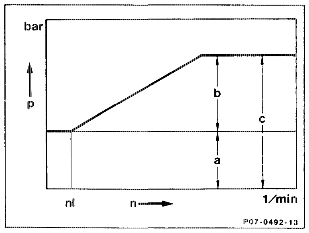
Absolute pressure with charge operation The intake air under atrnospheric pressure is further compressed by the turbocharger. Atmospheric and charge pressure together produce the absolute pressure prevailing in the charge air pipe of the engine.
nt Speed at the start of charge operation a Atmospheric pressure, corresponding to suction quantity b Charge pressure c Absolute pressure, corresponding to charge quantity Engine speed Pressure in bar
whiny =RA 07.1.1032-0010/14
L. Control rod travel sensor (L7)
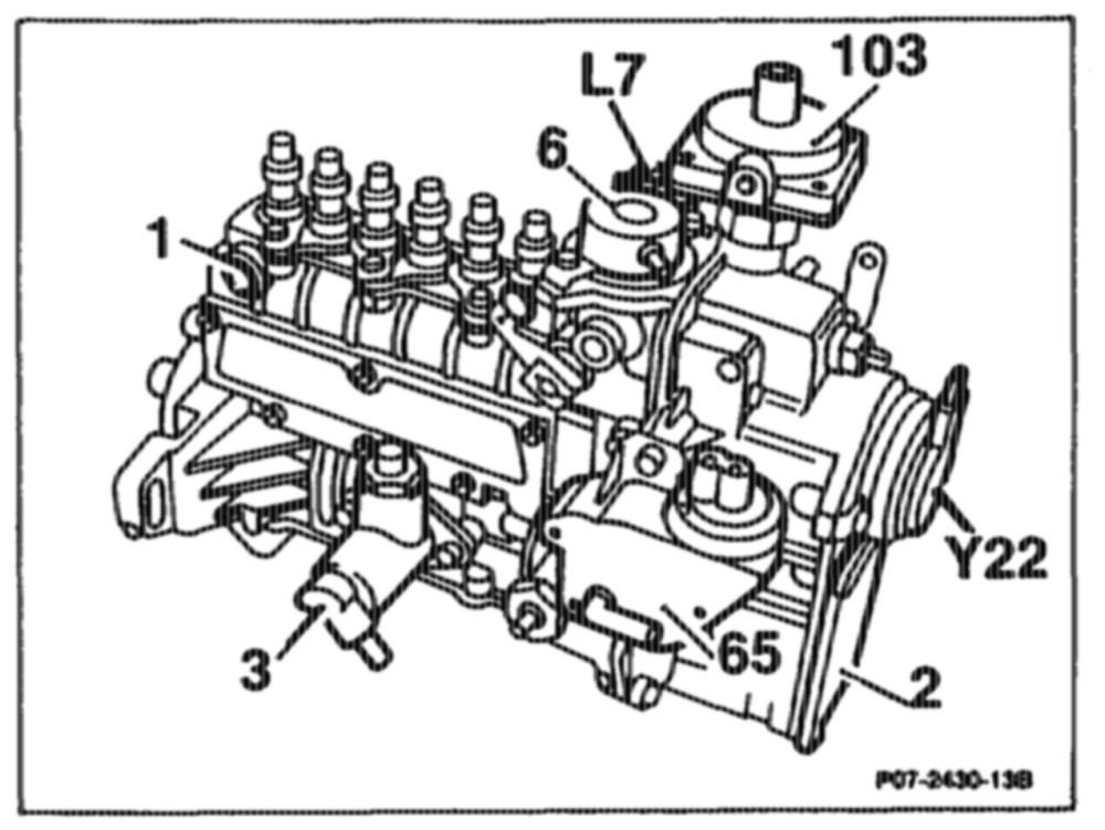
Installed in the governor of the injection pump. The control rod travel sensor consists of an iron core, two coils (measuring value and fixed value coil) and two short-circuit rings. It is connected to the electronic control unit by a 3-pin plug. The coils (b) and (d) are attached to the iron core (a) which is fixed in the housing. The shortcircuit ring (e) is connected to the control rod (2t) and is displaced with the latter without touching on the bottom leg of the iron core. The fixed value coil (b) and the short-circuit ring (c) are attached to the tap leg.
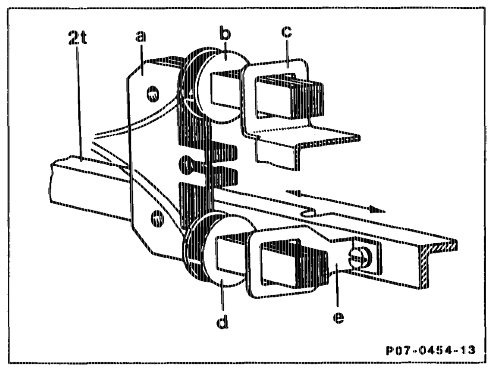
Function The fixed value coil (b) with the short-circuit ring (c) represents a constant inductance. Depending on the change in position of the control rod (2t), the distance between the short-circuit ring (e) and measuring coil (d) alters. The variable inductance which is thus produced is compared with the constant inductance. From this the electronic unit determines the control rod travel.
tie = RA 07.1.1032-0010/15
M. Reference impulse verification (RIV)
Two signals are required for checking start of A measuring instrument measures the time gap delivery when the engine is running (dynamic). of the two pulses and converts the result into an angular value, which is then indicated. ® TDC pulse from the crankshaft ® Reference impulse from the injection pump
Note
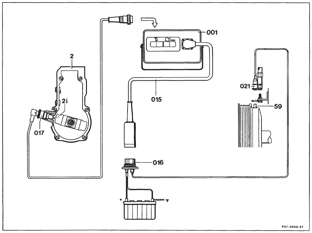
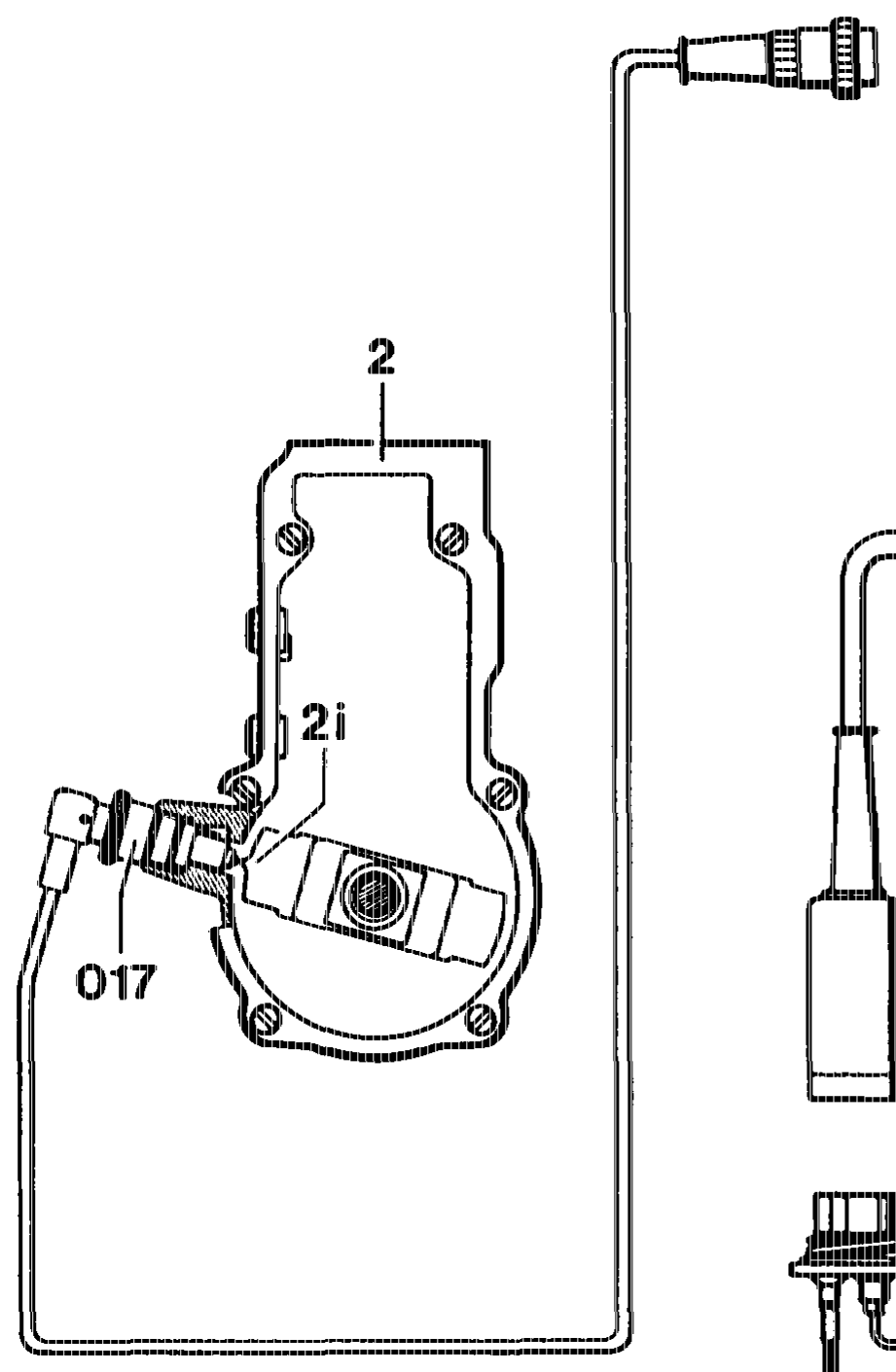
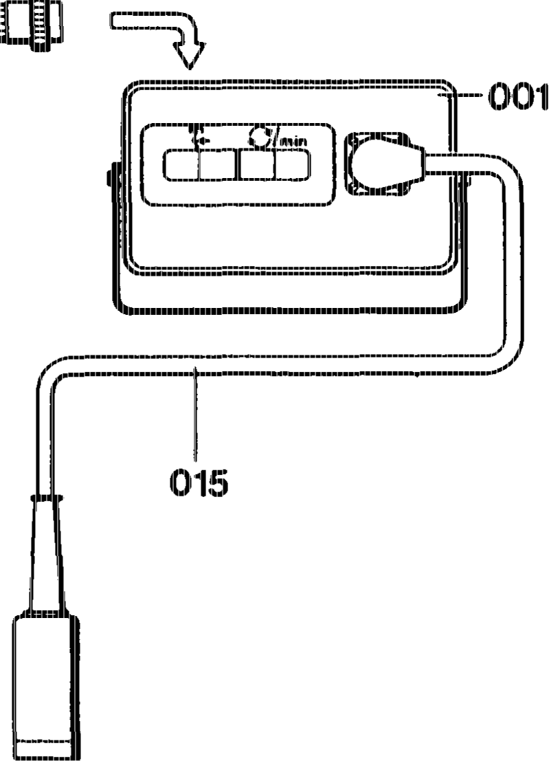
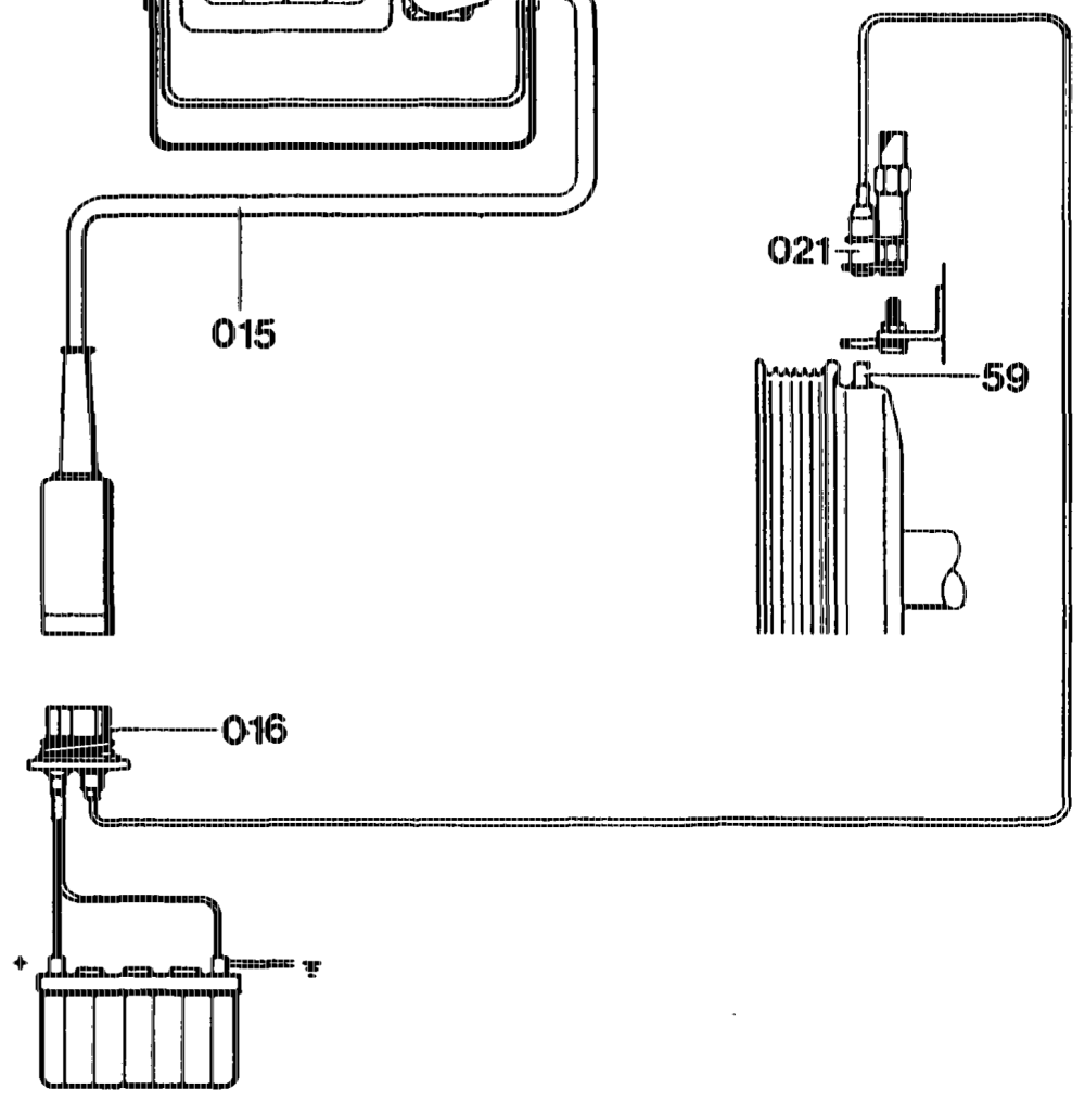
Both pulses are supplied by pulse generators. The position sensor can be used, as for To obtain a signal, the generator pins must be naturally aspirated engines, for checking start of moved passing the pulse generators at a delivery when the engine is not running minimum rate (idling speed). (stationary).
016 Diagnostic socket 001 Digital tester 017 Ri generator
2 Governor (injection pump) 021 TDC generator 2i Flyweight with Ri generator pin
59 TDC generator pin 018 Test cable
whine = RA 07.1.1032-0010/16
N. Electronic idle speed control (ELR)
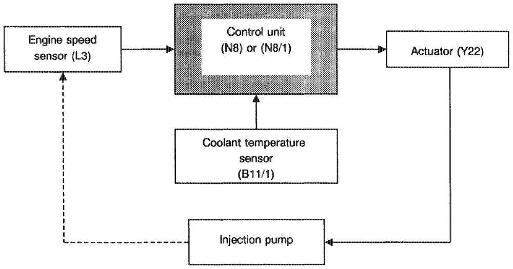
Function The starter ring gear speed sensor (L3) detects the engine speed (144 pulses/revolution) and passes these in the form of an alternating voltage to the electronic idle speed control unit (N8) or to the ELR/ARA control unit (N8/1). This processes the speed signal and performs a set/actual value comparison. Idling speed is maintained at a constant level by the actuator (Y22) irrespective of engine load. Set idling speed is raised in accordance with a specified characteristic curve by the temperature sensor (B11/1) at coolant temperatures <60 °C.
apts = RA 07.1.1032-0010/17
System diagnostics
Engine 602 The ELR system can be tested by means of the self-test routine integrated in the control unit. A signal can be retrieved with the test connector (X92 or X11/4), which provides concrete information regarding a component fault. The number of signals indicates whether and which component is faulty, or whether the components in the control loop are faulty.
Engine 603 Engine 603 is fitted with a control unit with diagnostics as of 05/88. Control unit designation: RO2 (was RO1).
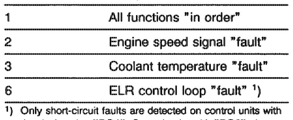
Pulse readout Component
the designation „RO1””. Control units with „RO2” also detect interrupt
epiihiy = RA 07.1.1032-0010/18
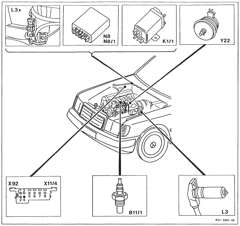
Location of components
B1i/1 Coolant temperature sensor N8/1 ELR/ARA control unit KI Overvoitage i N39 EDS control unit L3 Engine speed sensor, starter ring gear x14 Test coupling for diagnosis, pulse signal (8-pin) L3x Plug connection, engine speed sensor starter or X92 ring gear Y22 ELR actuator N8 ELR control unit
qian = RA 07.1.1032-0010/19
O. Anti-jerk control (ARA), engine 602.96 with manual transmission
General To damp the tendency to jerk on vehicles with manual transmission, a control solenoid has been fitted to the injection pump governor, which can reduce the injection quantity.
The control solenoid is actuated by an electronic control unit. This function, as well as the former ELR function is performed by the control unit located in the place of the former ELR control unit. Engine 602.96 with manual transmission CA) model year 1991 and as of model year 1992 Ca) Gm) and basic version Code 62/0 are fitted with a separate ARA control unit without ELR function. The ELR function is integrated in the EDS control unit.
Function The speed sensor (L3) detects the engine speed (144 pulses/revolution) and transmits this to the control unit (N8/1 or N8/2) in the form of an alternating voltage. Speed fluctuations or irregularities are recognised by the control unit (N8/1 or N8/2). The tendency to jerk is damped by briefly reducing the injection quantity. In order to achieve adequate damping when changing to overrun (no delivery), the overrun-jerking is minimised by a special damper.
In addition the facility exists to influence the sensitivity of the control with a resistance trimming plug, in order to damp the tendency to jerk under particular operating conditions.
aptiiay = RA 07.1.1032-0010/20
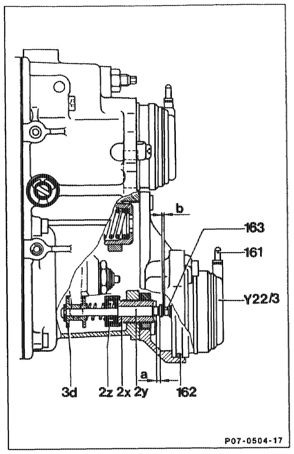
Electrical connection 161 O-ring 162 Lifter 163 ARA retainer 2x Sliding pin 2y Return spring 22 Orientation sleeve 3d ARA control solenoid Y2er3 Setting travel 0.9 + 1 mm (retainer travel) a = Control rod travel 1.35~-1.65 mm Play at full load stop 0.1–1.0 mm b
RA 07.1.1032-0010/21
ayia
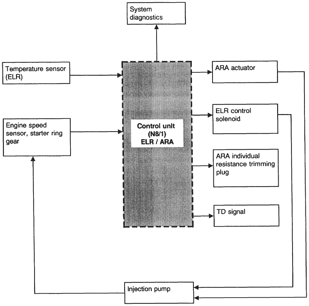
ARA/ELR block diagram
apts = RA 07.1.1032-0010/22
Location of components
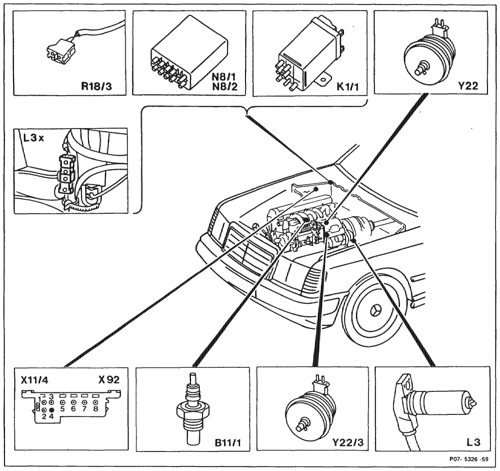
on os . Standard and (4D, version, Engine 602.96
Bit Coolant temperature sensor, electronic idle speed R18/3 ARA individual resistance trimming plug control (ELR) 11/4 Test coupling for diagnostics, pulse signal (8-pin) Ki/4 Overvoltage protection relay 87E, 7-pi or X92 L3 Engine speed sensor, starter ring gear Y22 Actuator, electronic idle speed contol L3x Plug connection, engine speed sensor, starter Y22/3 ARA control solenoid ring gear N&/1 ELRVARA control unit (not with & Neve ARA control unit (only with EDS
whine = RA 07.1.1032-0010/23
P. Facet pintle nozzle
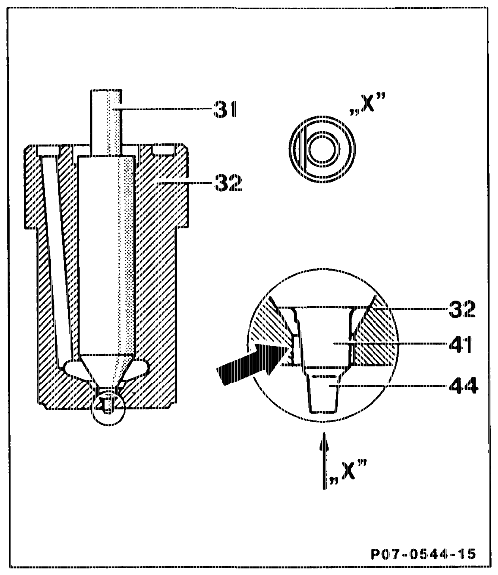
Bosch Designation DN 0 SD 265
The facet pintle nozzle differs from the pintle nozzle in having an oblique face angled at approx. 6° (arrow) on the throttling pintle (41), which improves the throttling effect.
Bosch Designation DN 0 SD 314
Facet depth on spray pintle reduced in order to improve the throttling effect and thus the idling quality of the engine.
31 Nozzle needle 32 = Nozzle body 41 Throttling pintle 44 Spray pintie
otis §=RA 07.1.1032-0010/24
Q. Nozzle holder
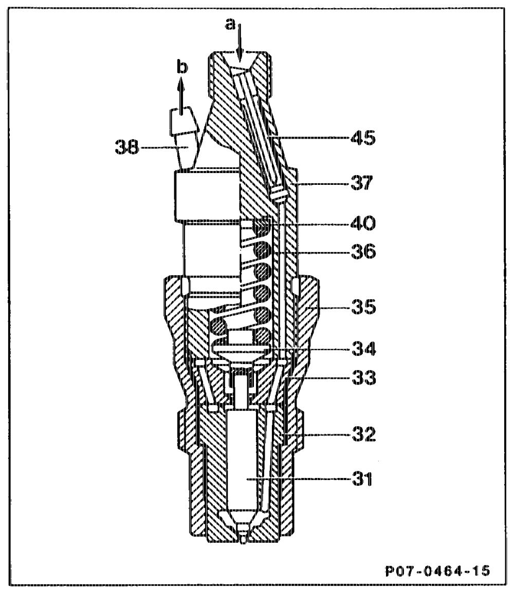
Bosch Designation: KCA 55, for oblique injection KCA 44, for vertical injection
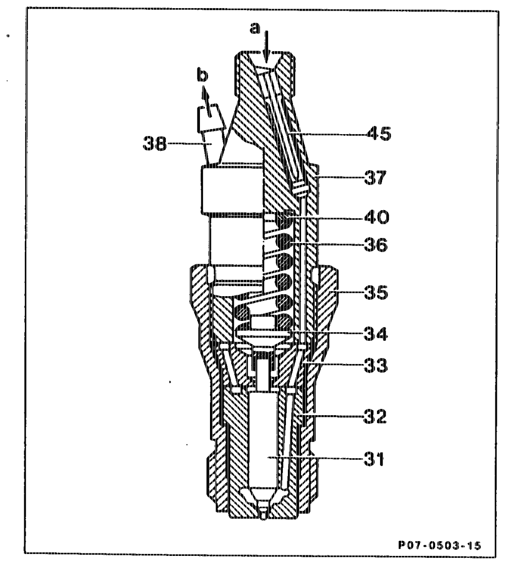
The thickness of the shim (40) determines the pre-load of the compression spring (36) and thus the opening pressure of the injection nozzle. The ejection pressure can be set by fitting shims of different thicknesses. The fuel flows to the nozzle seat through the respective inlet orifice (a) in the holder (37), intermediate disk (33) and injection nozzle. During the injection process, the injection pressure raises the no @ needle, and fuel flows through the annular ori at the throttling pintle into the pre-chamber. Onc @ the injection pressure drops, the compre sion spring (36) pushes the nozzle needle (31) ba ick down onto its seat; the injection process is completed.
Nozzle holder KCA 27 S 55 oblique injection) (for Nozzle needie 31 Nozzle body 32 Intermediate disk 33 Pressure pin 34 35 Nozzle tensioning nut Compression spring 36 Holder 37 Leak oil port 38 Shim 40 Inlet orifice 45 Fuel inlet a Leak fuel (return) b
uti =RA 07.1.103: 0010/25
R. Oblique injection
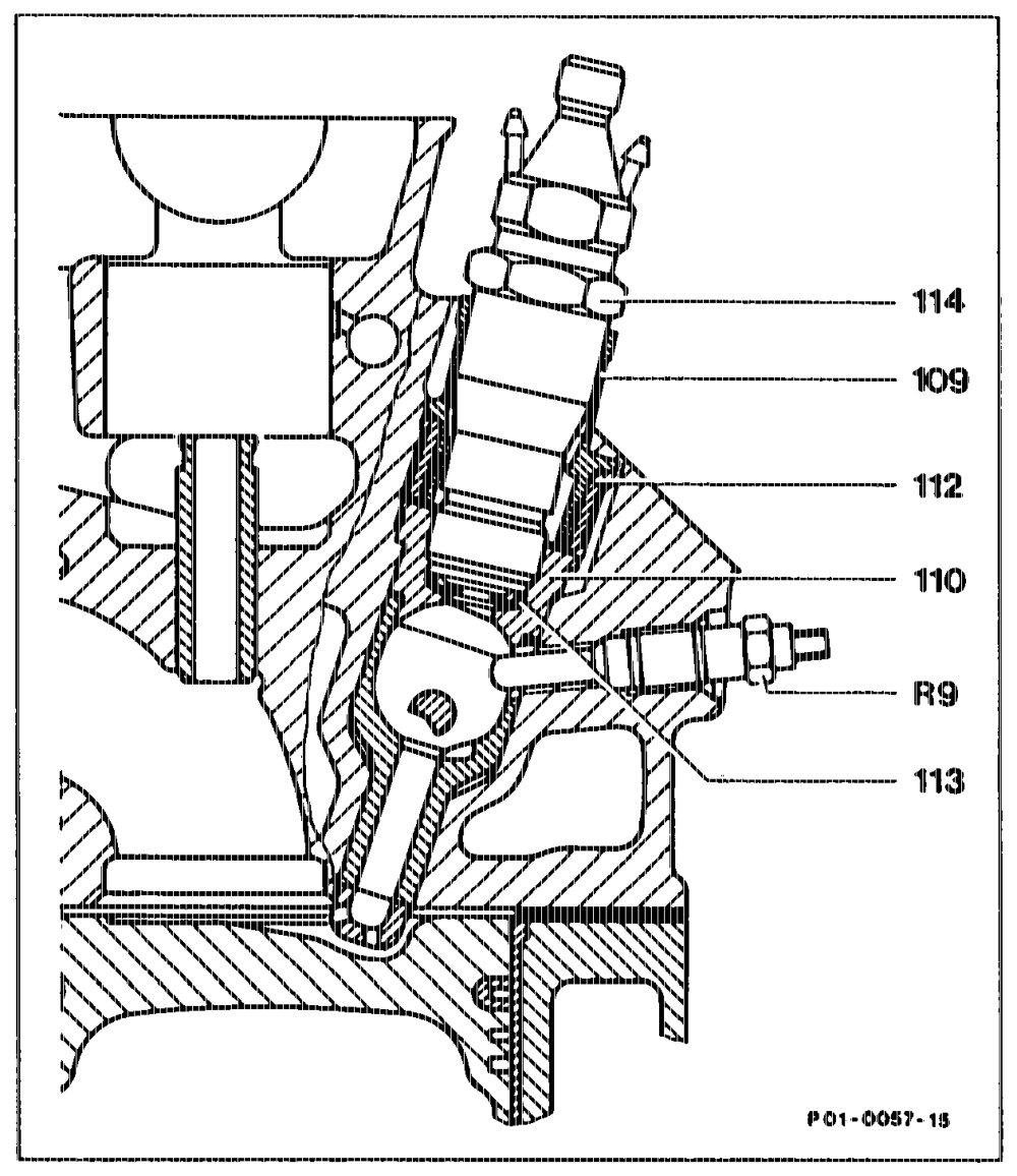
The nozzle holder combination is screwed into top section of the prechamber tilted by 5° ative to the longitudinal axis of prechamber. This oblique injection produces an even more intensive blending of air and fuel.
R9 Glow plug 109 Sealing sleeve 110 Prechamber 112 Threaded ring 113 Sealing shim 114 Nozzle holder combination
Together with the prechamber modification, this offers the following benefits: ® Improved cold start ® More favourable air/fuel blending as a result of shorter glow plug (now 23 mm was previously 25 and 27 mm) in combination with recess and the concave in the ball pin. ® Particle reduction and improvement in hydrocarbons and carbon monoxide.
phim =RA 07.1.1032-0010/26
S. Injection lines
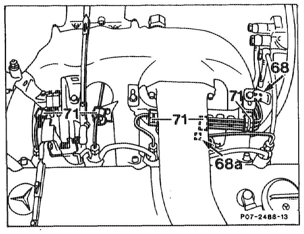
The injection lines are designed so as to allow the injection pump to swivel when the engine is i running.
The plastic clips (68 and 68a) must be fitted as close as possible to the radius of the injection lines (arrows). The plastic clips (71) must be locked in place.
«phim = RA 07.1.1032-0010/27 switch) T. Vacuum engine stop with car key (glow star
a) Models 124, 126, 201
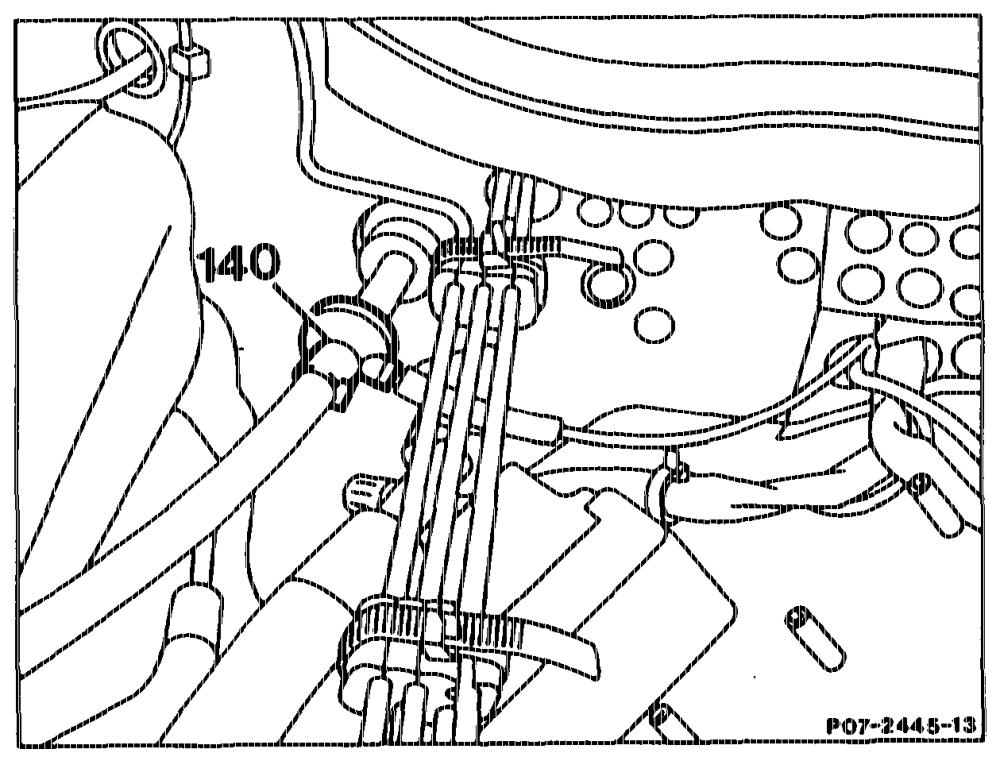
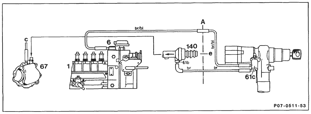
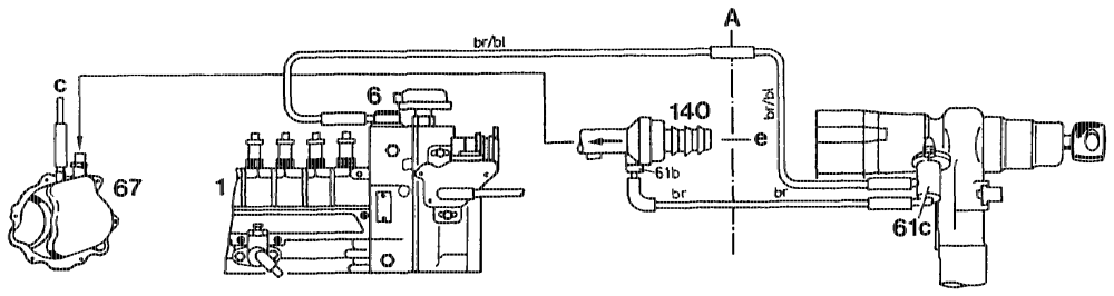
The vacuum for the key-operated engine stop is supplied by the check valve (140) of the main vacuum fine.
Vacuum line routing Intermediate panel
1 Injection purnp A Other ancillaries
6 Vacuum unit (stop) c To brake booster 6ic Valve, glow start switch e
67 Vacuum pump 140 Check valve/main vacuum line
quits = RA 07,1.1032-0010/28 b) Model 140, engine 603.971 Gsa) model year 1992
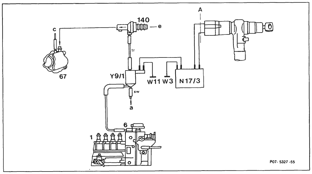
The key-opera d engine stop is no longer actuated via the glow start switch valve (61c) but via an electric switchover valve (Y9/1) and via a relay (N17/3), which at the same time also switches off the fuel.
Vacuum line routing
1 Injection pump Y9/1 Key-operated stop switchover valve
6 Stop unit
67 Vacuum pump A Intermediate panel 140 Check valve/main vacuum line N17/3 Key-operated stop relay (fuel shutoff) a Air admission to vehicle interior W3 Ground, front left wheelhouse c Other anc $ wii Ground, engine 8 To brake booster
atts = RA 07.1.1032-0010/29
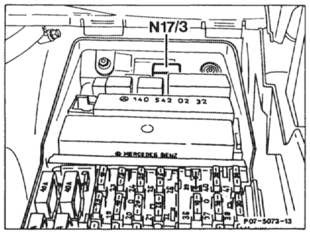
Key-operated engine stop relay (N17/3), keyoperated engine stop switchover valve (¥9/1) The key-operated engine stop relay ve is actuated for about 3 switched off and operates pe engine stop switchover valve (Y9/1).
N17/3— Key-operated engine stop relay (fuel shutoff)
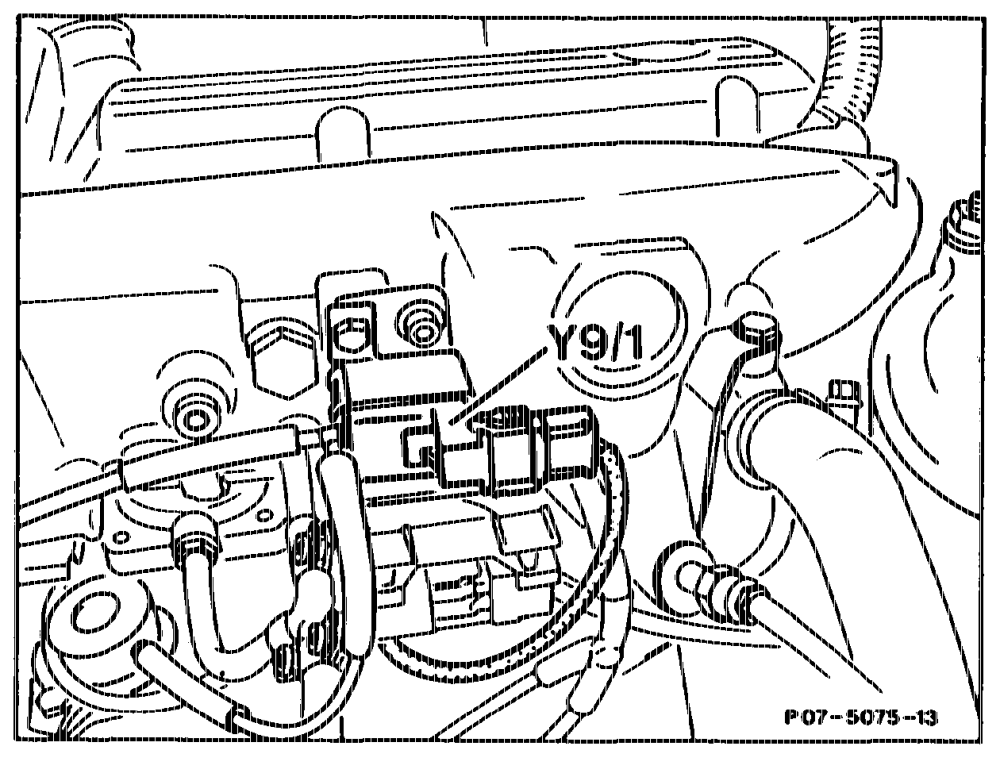
A vacuum of about 500 mbar exists at the keyoperated engine stop switchover valve (Y9/1). After this valve is actuated, the vacuum which exists at the valve operates the stop unit at the injection pump pneumatically and moves the control rod into the stop position.
Y9″ ~~“ Key-operated engine stop switchover valve
qtthipy ~=FLA 07.1.1032-0010/30
U. Electronic diesel system (EDS)
a) General
The EDS control unit (N39) processes the As a result of the integrated self-test program, faults are detected and stored which simplifies electronic idle speed control with exhaust gas diagnostics. recirculation and charge pressure control.
Design and operating principle:
Location of components Function diagrams Influencing variables of electronic diesel system (EDS) Electronic idle speed control (ELR) Exhaust gas recirculation (ARF) Recirculating air control for trap oxidizer (only Gs4) California engine 603.96 model year 1986/87). Charge pressure control (P2 control) Engine 602.96 Basic version Code 62/0 as of 06/91 as of model year 1990 CH) as of model year 1991 CA) Ci) as of model year 1992 Engine 603.971 Gsa) as of model year 1992 System diagnostics
utthis = =RA 07.1.1032-0010/31
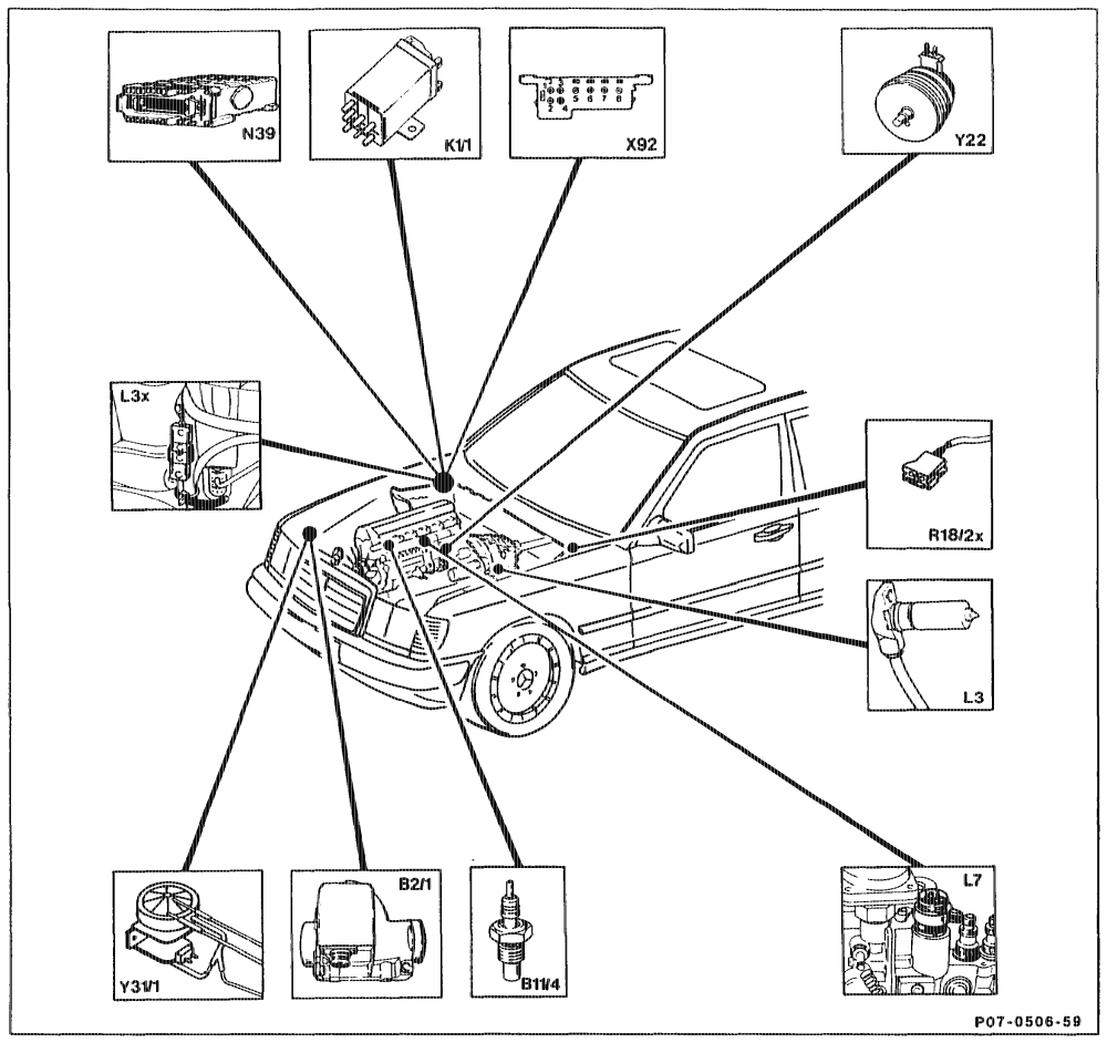
b) Location of components
Model year 1988 Cs) B21 Air flow sensor potentiometer with intake air L7 Control rod travel sensor temperature sensor, EDS N39 EDS control unit Bi1/4 Coolant temperature sensor (92 Test connector Ki/1 Overvoltage protection relay ELR actuator L3 Engine speed sensor ~ starter ring gear Y3i/1 ARF vacuum transducer Plug connector, engine speed sensor ~ starter R18/2x Plug connectioVvARF reference resistor L3x ring gear
tiie = RA 07.1.1032-0010/32
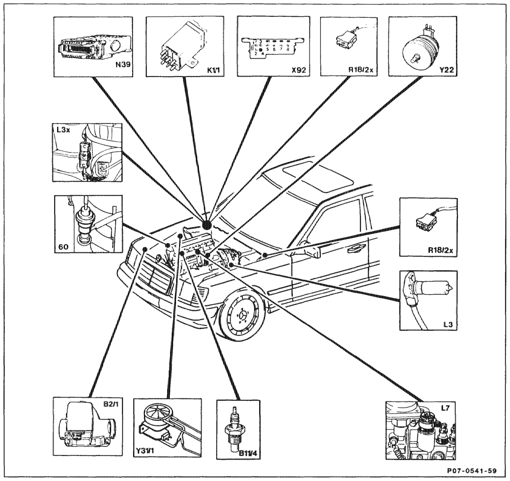
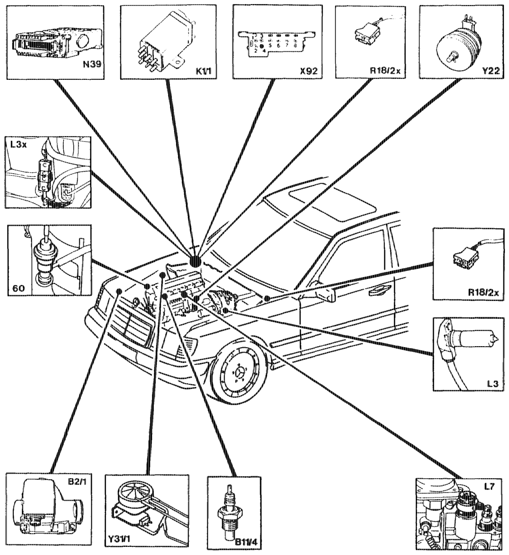
Model Year 1989 CA) C2, Models 124, 201 with Engine 602.96 EDS control unit N39 Bat Air flow sensor potentiometer with intake air Plug connectioWARF reference resistor temperature sensor, EDS R18/2x Test connector x92 Bi1/4 Coolant temperature sensor ELR actuator Y2a2 Ki Overvoltage protection relay Lg Engine speed sensor ~ starter ring gear ARF vacuum transducer YRIA L3x Plug connector, engine speed sensor ~ starter ARF valve 60 ring gear L7 Control rod travel sensor
apie = RA 07.1.1032-0010/33
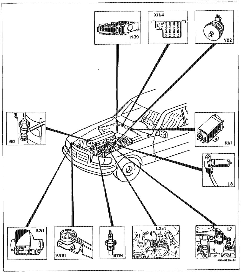
Bat Air flow sensor potentiometer with intake air N39 EDS control unit temperature sensor, EDS 11/4 Test connector Bii/4 Coolant temperature sensor Y22 ELR actuator Kw Overvoltage protection relay Y31/4 ARF vacuum transducer 1) Engine speed sensor ~ starter ring gear 60 ARF valve L3x Plug connector, engina speed sensor ~ starter ring gear L7 Control rod travel sensor
«phi = RA 07.1.1032~-0010/34
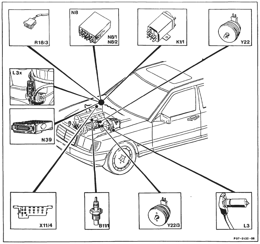
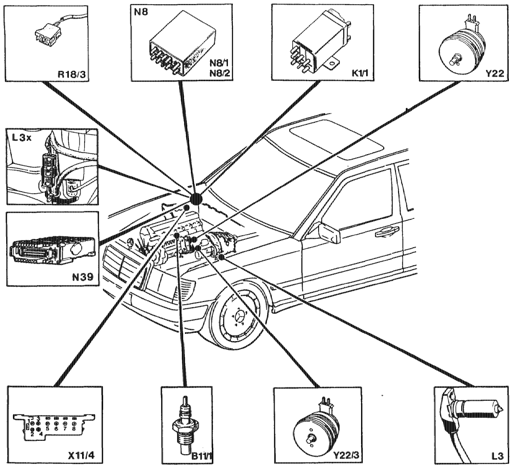
Model Year 1990 Standard, CAD, Gi), Engine 602.96 EDS control unit (CA) only) B11 Coolant temperature sensor, ELR N39 Ki Overvoitage protection relay A183 ARA reference resistor L3 Engine speed sensor — starter ring gear X14 Test connector for diagnosis (pulse signal) L3x Plug connector, engine speed sensor — starter Y22 ELR actuator ring gear Y22/3 ARA actuator N8 ELA control unit N8&/1 ELRA/ARA control unit (manual transmission only) N8/2 ARA control unit
aon = RA 07.1.1032-0010/35
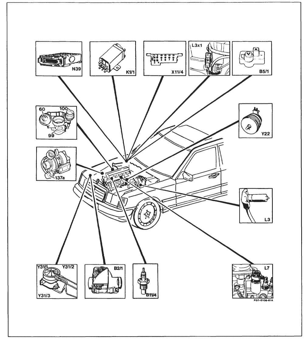
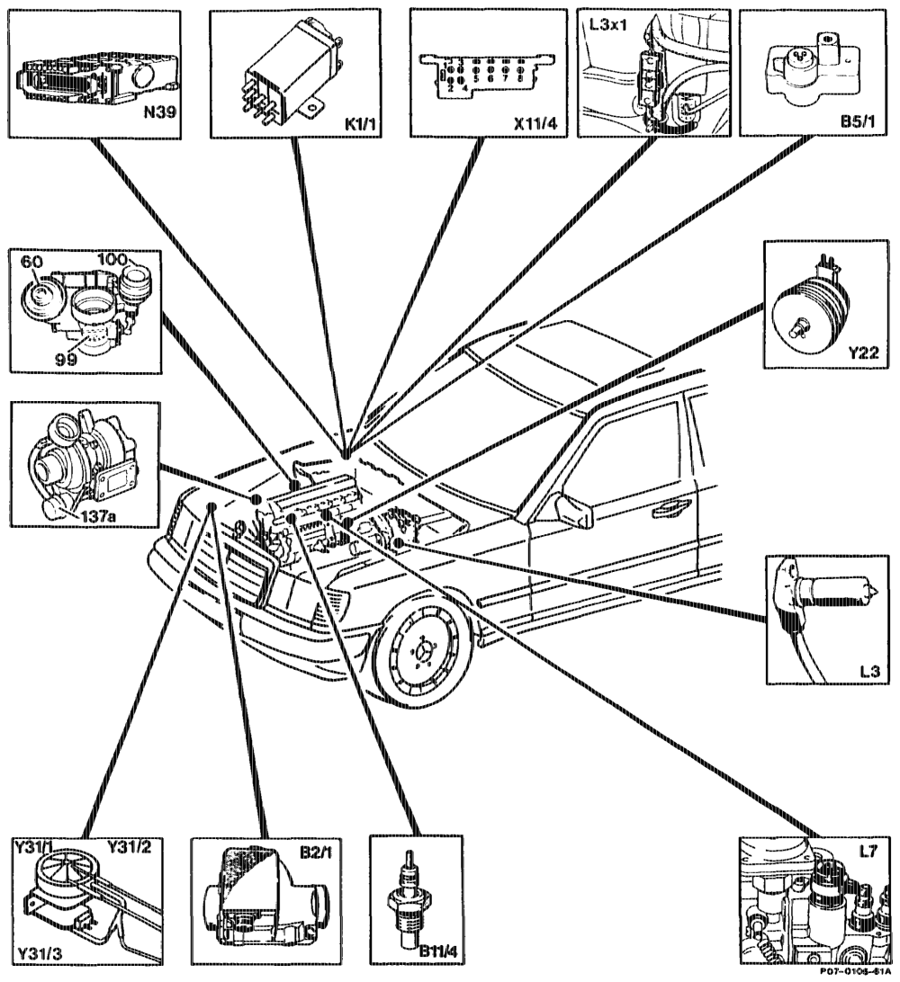
Model Year 1990, Gs), Engine 602.962 Bat Air flow sensor potentiometer with intake air Y22 ELR actuator temperature sensor, EDS YS ARF vacuum transducer B5/1 Pressure sensor (EDS) Y312 Vacuum transducer – pressure control flap Y3u3 B14 Coolant temperature sensor Vacuum transducer — charge pressure control ARF vaive KAA Overvoltage protection relay 60 La Engine speed sensor – starter ring gear Pressure control flap in micture housing Land Plug connector, engine speed sensor — starter 100 Vacuum unit, pressure control flap 137a Vacuum unit, charge pressure control valve ring gear L7 Control rod travel sensor X14 Test connector
phi = RA 07.1.1032-0010/36
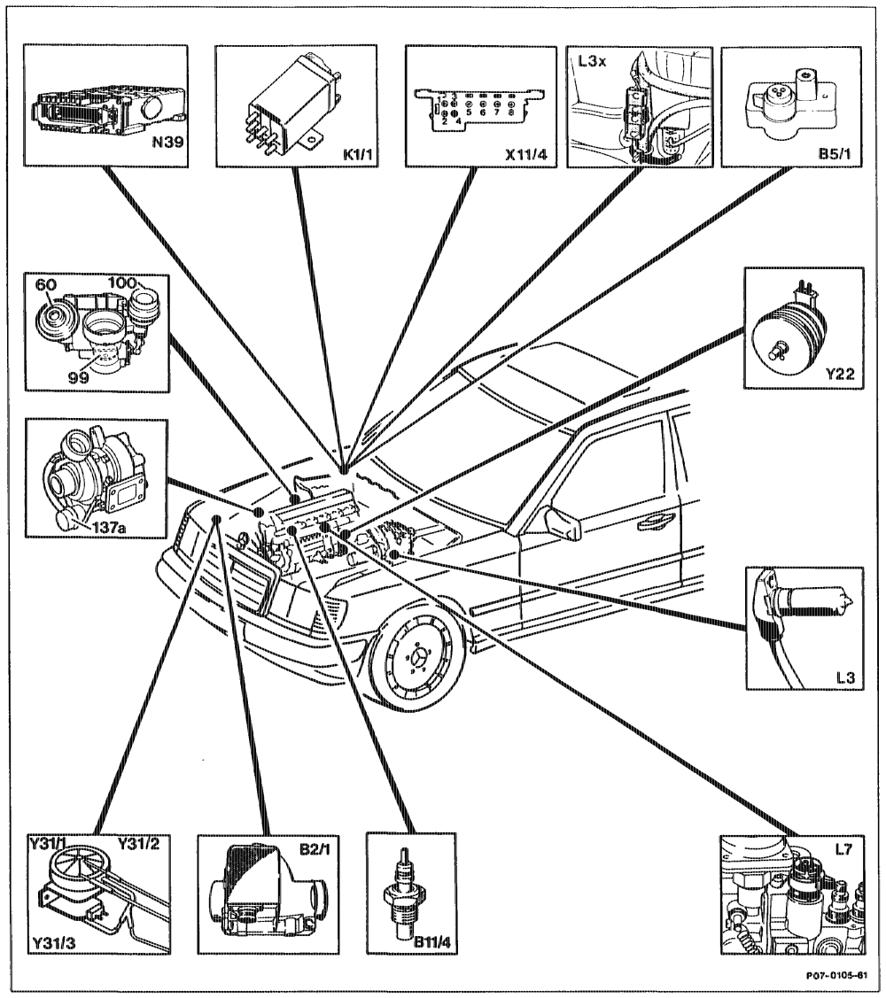
Bai Air flow sensor potentiometer N39 EDS control unit B51 EDS pressure sensor 11/4 Test connector B11/4 Coolant temperature sensor ‘ ELR actuator K1i/1 Overvoltage protection relay ARF vacuum transducer L3 Engine speed sensor – starter ring gear Vacuum transducer pressure control flap Lax Plug connector, engine speed sensor — starter 31/3 Vacuum transducer – charge pressure control ring gear 60 ARF valve L7 Control rod travel sensor
eotiian = RA 07.1.1032-0010/37
vii RA 07.1.1032-0010/38
Model Year 1992, Basic Version Code 62/0 (as of 06/91), CAD Gin) GH) CG, Engines 602.96, 603.96 in Model 124
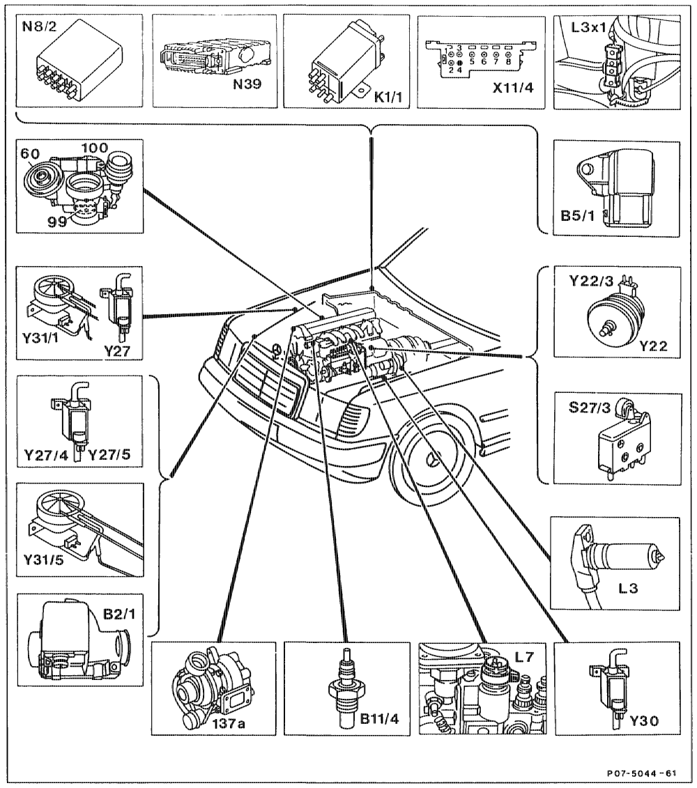
Air flow sensor potentiometer with intake air ARF switchover valve Ba/1 Y27 Switchover valve, left boost pressure control, temperature sensor, electronic diesel system Y27/4 EOS pressure sensor, engine 602.96 engine 602.96 BS/1 Coolant temperature sensor, electronic diesel Switchover valve, right vacuum control flap, Y27/5 B11/4 engine 602.96 system Switchover valve, engine overload protection, Ki Overvoltage protection relay 87E (9-pin) Y30 engine 603.96 La Engine speed sensor, starter ring gear Y31/1 ARF vacuum transducer Plug connection, engine speed sensor, starter L3x1 Y3U5 Vacuum transducer, boost pressure ring gear L7 Control rod travel sensor controlvacuum control flap, engine 602.96 ARA control unit (manual transmission only, N8/2 ARF valve engine 602.96) 60 Vacuum control flap in mixing housing, engine EDS control unit 99 N39 $2773 ARF microswitch 602.96 Vacuum unit, vacuum control flap, engine 602.96 x4 Test coupling 100 Vacuum unit, boost pressure control valve, 137a Y22 ELR actuator ARA actuator (manual transmission only, engine engine 602.96 Y22/3 602.96)
utiiije = RA 07.1.1032-0010/39
thin =RA 07.1.1032-0010/40
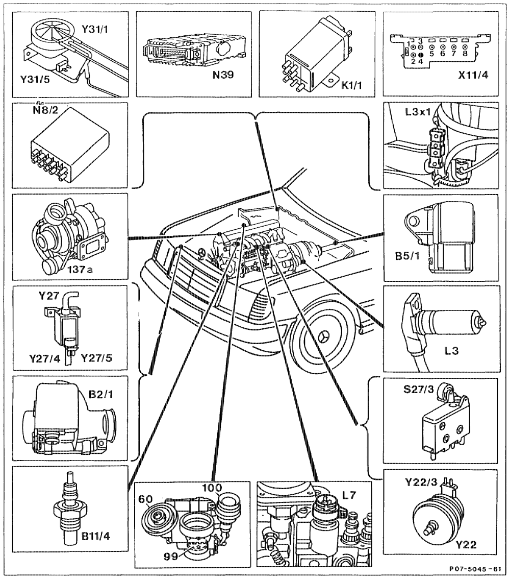
Model Year 1992, Basic Version Code 62/0 (as of 06/91), CAD GIN), Engine 602.96 in Model 201 Air flow sensor potentiometer with intake air ELR actuator Bat Y22 temperature sensor, electronic diesel system Y¥22/3 ARA actuator (manual transmission only) EDS pressure sensor B5S/1 Y27 ARF switchover valve Coolant temperature sensor, electronic diesel B11/4 Y27/4 Boost pressure control switchover valve Y27/5 Vacuum control flap switchover valve system Overvoltage protection relay 87E, 7-pin K1i/1 Y31 ARF vacuurn transducer Engine speed sensor, starter ring gear L3 Y31/5 Vacuum transducer/ooost pressure Plug connection, engine speed sensor, starter control/vacuum contro flap L3x1 ring gear Control rod travel sensor ARF valve L7 ARA control unit (manual transmission only) Vacuum control flap in mixing housing Na/2 EDS control unit Vacuum unit, vacuum control flap N39 $27/3 Vacuum unit, boost pressure control valve ARF microswitch 11/4 Test coupling
otthijm = RA 07.1.1032-0010/41
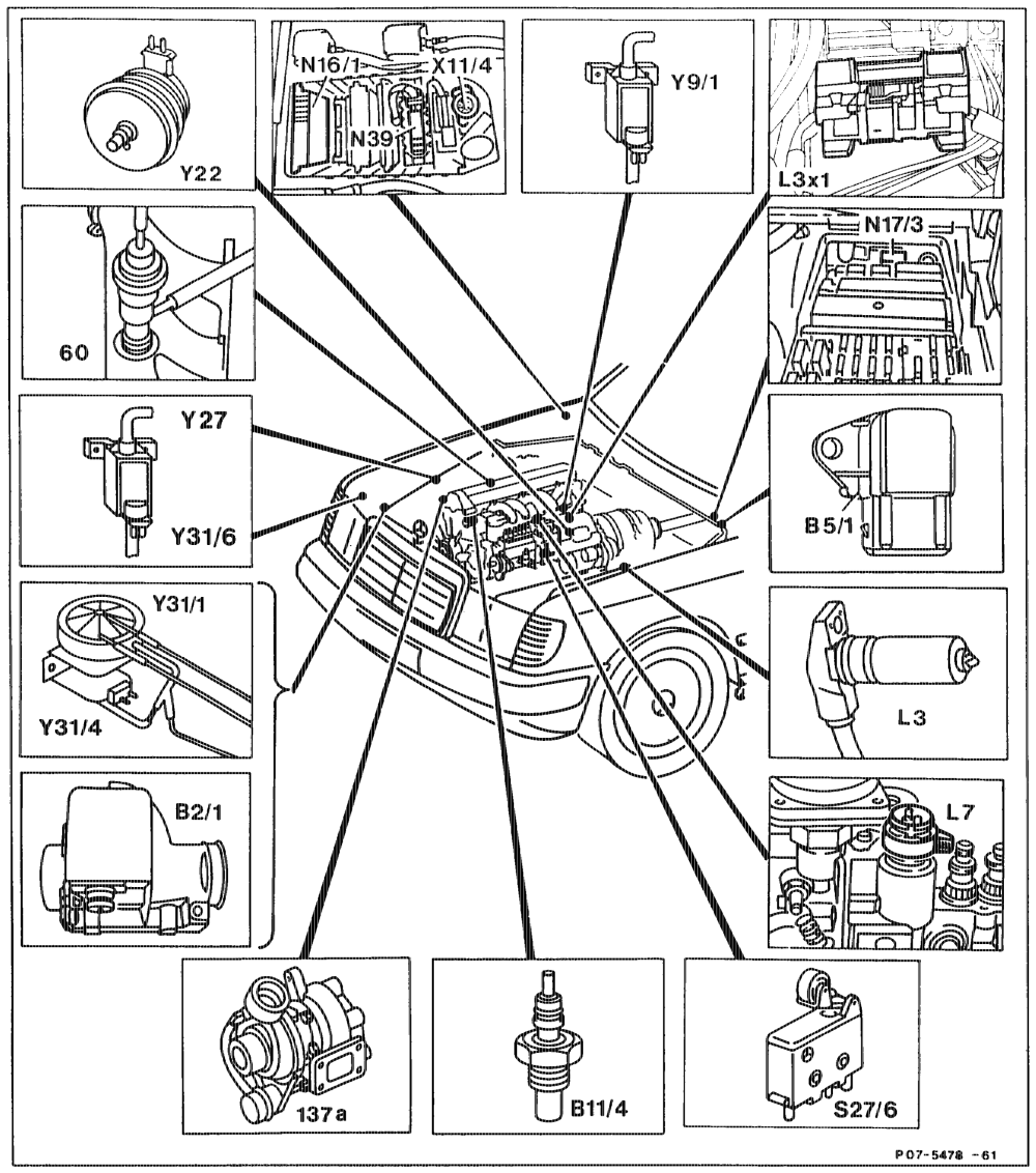
Model Year 1992, G4), Engine 603.971, Model 140 EDS control unit Air flow sensor potentiometer with intake air N39 Bat S276 AIC compressor cutouv/ARF temperature sensor, electronic diesel system EDS pressure sensor X11/4 Test coupling B5/1 YO” Key-operated engine stop switchover valve EDS coolant temperature sensor B11/4 Engine speed sensor, starter ring gear Y22 ELR actuator 3 Plug connection, engine speed sensor, starter Y27 ARF switchover valve Lax YS ARF vacuum transducer nng gear Y31/4 Control rod travel sensor Boost pressure control vacuum transducer L7 Y316 Boost pressure cutoff switchover valve N16/1 Base module Key-operated engine stop relay N17 ARF valve 60 Vacuum unit, boost pressure control valve 137a
eptthiyn §~=RA 07.1.1032-0010/42
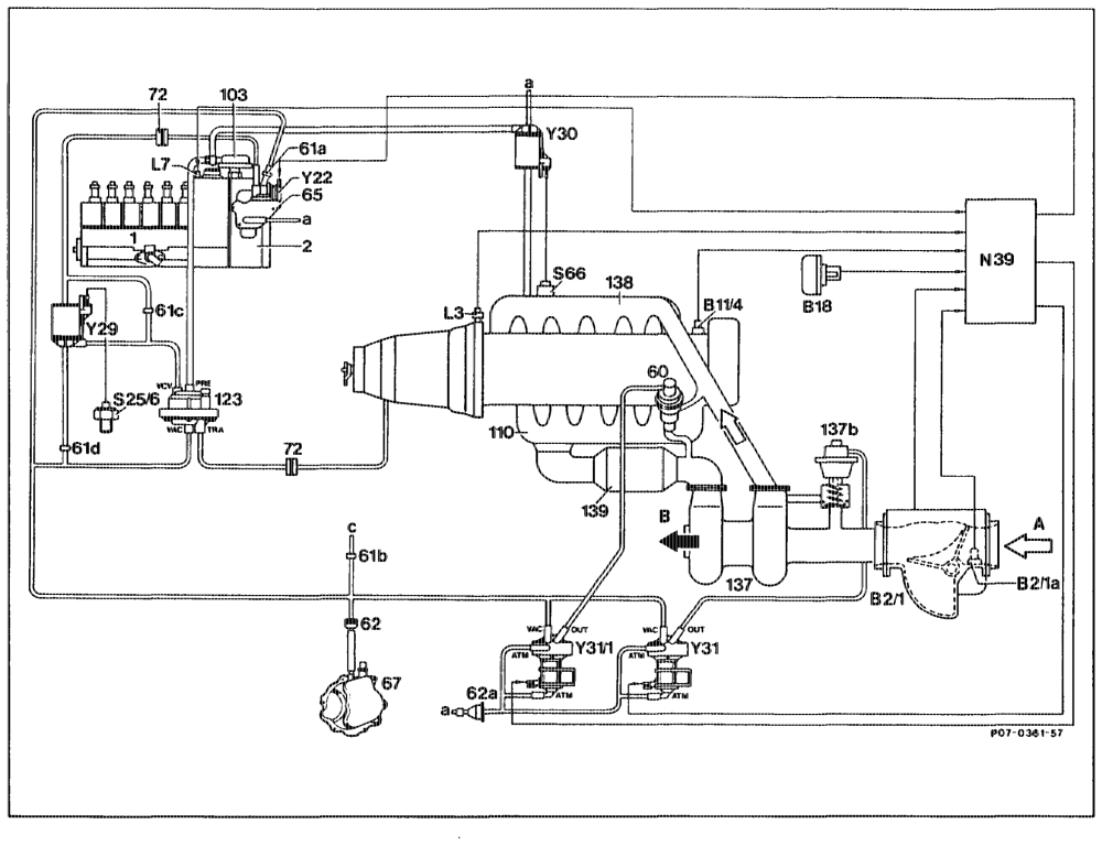
c) Function diagrams
pithy = RA 07.1.1032-0010/43
Injection pump Control rod travel sensor 1 L7 EDS control unit 2 N3g overnor Exhat s recirculating valve S25/6 60 Temperature switch 50 °C 6la Restriction, blue S66 Switch, engine overload protection 61b Restriction, orange Y22 Actuator Switch-over valve, vacuum amplifier 61c Restriction Restriction Switch-over valve, engine overload protection 61d Fitter Vacuum transducer, recirculating air valve 62 Fitter (model 126 only) 62a 65 Vacuum control valve Vacuum transducer, exhaust gas recirculating Vacuum pump 67 valve Damper Fresh air flow to car interior 72 103 ALDA unit Intake air Exhaust manifold Exhaust gas 110 Vacuum amplifier 123 Exhaust gas turbocharger Pressure and vacuum connections at vacuum 137 Recirculating air valve (Califomia onty) 137b transducer or vacuum amplifier Charge air distribution pipe 138 Trap oxidizer (California onty) Charge pressure from ALDA unit 139 PRE Bani Air flow sensor potentiometer TRA To vacuum unit of automatic transmission Bafa VAC Intake air temperature sens Vacuum from vacuum pump Coolant ternperature se B14 VCV To vacuum control valve B18 Altitude sensor ATM Fresh air flow to car interior OUT L3 Engine speed sensor, starter ring gear Exhaust gas recirculation to exhaus’ recirculating valve or recirculating air
qettajjyn
RA 07.1.1032-0010/44
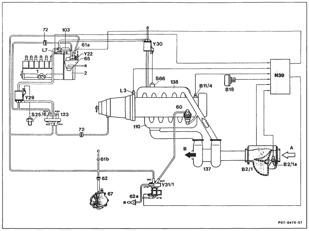
Engine 603.960 in Model 126 Model Year 1986 @sa) Federal Engine 602.961 in Model 201 Model Year 1987 Gsa) Federal Temperature switch 50 °C S256
1 Injection pump
Switch, engine overload protaction $66
2 Governor
60 Exhaust gas recirculating valve Actuator Y22 Switch-over valve, vacuum amplifier Y29 61a Restriction, blue Switch-over valve, engine overload protection Y¥30 61b Restriction, orange Vacuum transducer, exhaust gas recirculating YI
62 Fitter valve 62a Fitter Fresh air flow to car interior
65 Vacuum control valve o> Intake air
67 Vacuum pump Exhaust gas
72 Damper 103 ALDA unit Pressure and vacuum connections at vacuum 110 Exhaust manifold transducer or vacuum amplifier 123 Vacuum amplifier 137 Exhaust gas turbocharger Charge pressure from ALDA unit PRE 138 Charge air distribution pipe To vacuum unit of automatic transmission Ban Air flow potentiometer Bafta Intake air temperature sensor VAG Vacuum from vacuum pump vCv To vacuum control valve Bit/4 Coolant temperature sensor ATM Fresh air flow to car interior B18 Altitude sensor Exhaust gas recirculation to exhaust gas L3 Engine speed sensor, starter ring gear OUT recirculating valve or recirculating air valve
7 Control rod travel sensor N39 EDS control unit
ome = RA 07.1.1032-0010/45
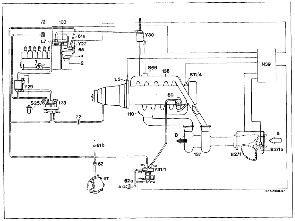
Engine 603.96 in Model 124, Model Year 1988 C)
1 Injection purnp $2546 Temperature switch 50 °C
2 Govemor $66 Switch, engine overload protection
60 Exhaust gas recirculating valve Y¥22 Actuator 6la Restriction, blue Y29 Switch-over valve, vacuurn amplifier 61b Restriction, orange ¥30 Switch-over valve, engine overload protection
62 Filter sw Vacuum transducer, exhaust gas recirculating 62a Filter valve
65 Vacuum control valve a Fresh air flow to car interior
67 Vacuum pump A Intake air
72 Damper B Exhaust gas 103 ALDA unit 110° Exhaust manifold Pressure and vacuum connections at vacuum 123 Vacuum amplifier transducer or vacuum amplifier 137 Exhaust gas turbocharger 138 Charge air distribution pipe Charge pressure from ALDA unit Ba Air flow sensor potentiometer tA, To vacuum unit of automatic transmission BeNa Intake air temperature sensor VAG Vacuum from vacuum pump B14 Coolant temperature sensor VCV To vacuum control valve L3 Engine speed sensor, starter ring gear ATM Fresh air flow to car interior L7 Control rod travel sensor OUT Exhaust gas recirculation to exhaust gas N39 EDS control unit recirculating valve or recirculating air valve
spt = RA 07.1.1032–00 10/46
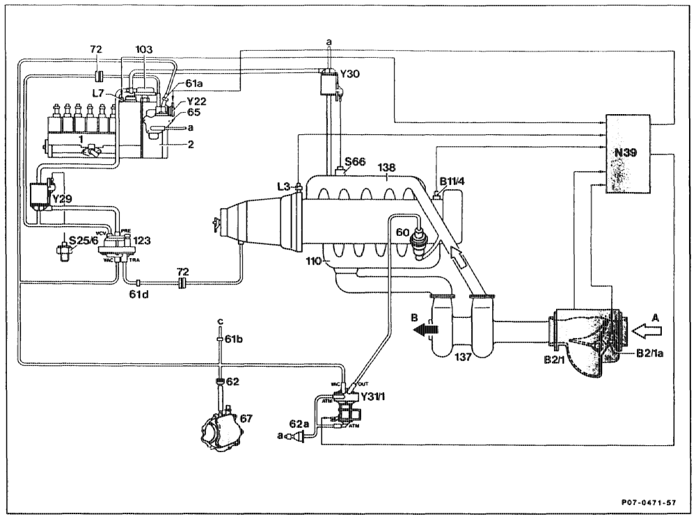
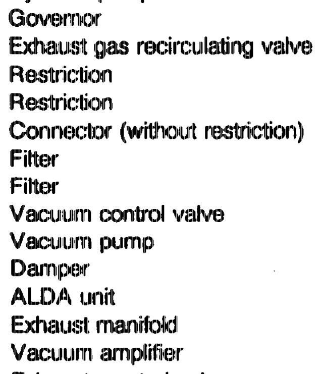
Engine 602.96, 603.96, Model Year 1989 CA) G>, Model Year 1991 CN) injection pump NQgO EDS contol unit 1 Govemor S256 Temperatura switch 50 °C 2 Switch, engine overioad protection Exhaust gas recirculating valve 60 6la Rastriction, blue Actuator Switch-over valve, vacuum amplifier 61b Restriction, orange Connector (without restriction) Switch-over valve, engine overload protection 61d Fitter Vacuum transducer, exhaust gas recirculating Filter valve Fresh air flow to car interior Vacuum control valve Vacuum pump Intake air Damper Exhaust gas ALDA unit Exhaust manifold Pressure and vacuum connections at vacuum Vacuum transducer, up to 01/91 transducer or vacuum amplifier Exhaust gas turbocharger Charge air distribution pipe Charge pressure from ALDA unit PRE Air flow sensor potentiometer TRA To vacuum unit of automatic transmission Vacuum from vacuum pump VAC Intake air temperature sensor VCVv Coolant temperature sensor To vacuum control valve Fresh air flow to car interior ATM Engine speed sensor, starter ring gear Control rod travel sensor Exhaust gas recirculation to exhaust gas OUT recirculating valve or recirculating air valve
eotiiiyn = RA 07.1.1044-0010/47
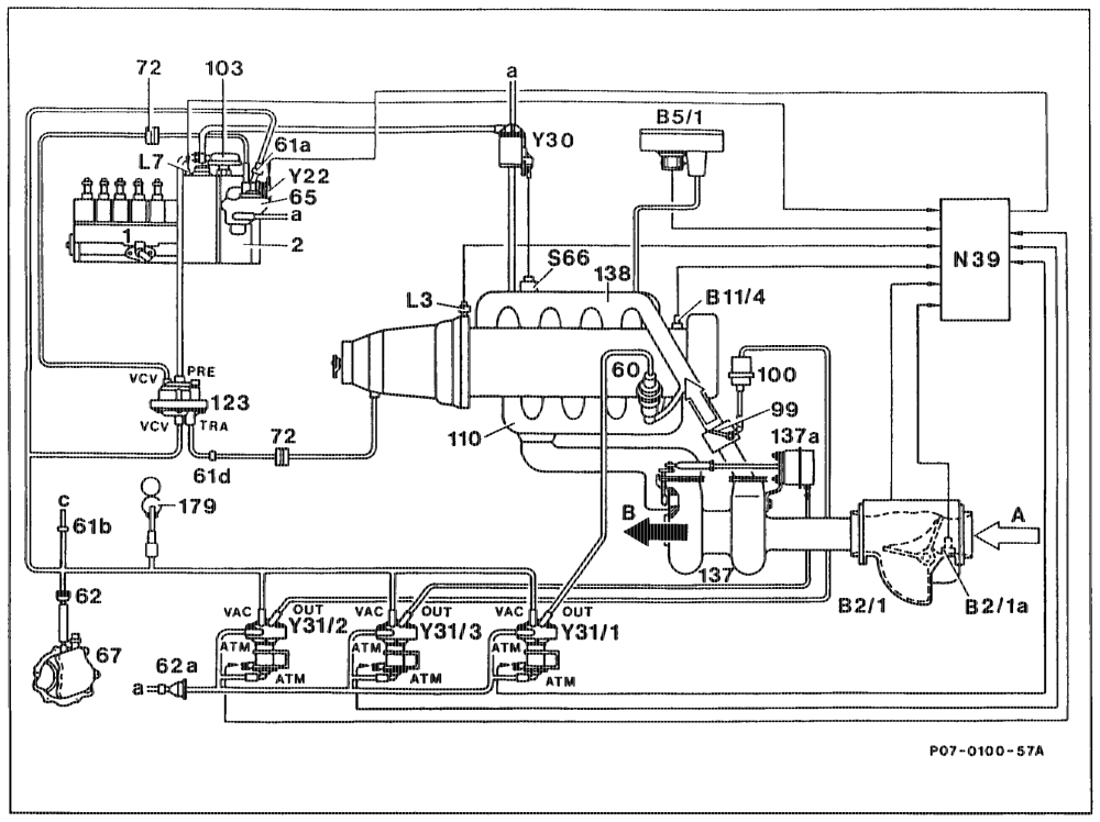
Engine 602.962, @s® Model Year 1990 and GH) © Model Year 1991
1 Injection pump N39 EDS control unit
2 Governor S66 Switch, engine overload protection
60 Exhaust gas recirculating valve Y22 ELR actuator 6la Restriction Y30 Switchover valve, engine overload protection 61b Restriction YS Vacuum transducer, exhaust gas recirculating 61d Connector (without restriction) valve
62 Filter ¥31/2 Vacuum transducer, pressure control flap 62a Fitter Y31/3 Vacuum transducer, charge pressure control
65 Vacuum control valve
67 Vacuum pump a Fresh air flow to car interior
72 Darnper c Other ancillaries
99 Pressure control flap in mixture housing A Intake air 100 Vacuum unit, pressure control flap B Exhaust air 103 ALDA unit 110 Exhaust manifotd Pressure and vacuum connections at vacuum 123 Vacuum transducer, up to 01/91 transducer or vacuum amplifier 137 Exhaust gas turbocharger 1397a Vacuum unit, charge pressure control valve PRE Charge pressure from ALDA unit 138 Charge air distribution pipe TRA To vacuum unit of automatic transmission 179 Vacuum reservoir VAC Vacuum from vacuum pump Bel Air flow sensor potentiometer with intake air VCV To vacuum control valve temperature sensor, EDS. ATM Fresh air flow to car interior Baa Intake air temperature sensor OUT Output from vacuum transducer Y31/1 to ARF BSA EDS pressure sensor valve Bi EDS coolant temperature sensor OUT Output from vacuum transducer Y31/2 to vacuum L3 Engine speed sensor, starter ring gear unit of pressure control flap L7 Control rod travel sensor OUT Output from vacuurn transducer Y31/3 to vacuum unit of charge pressure control valve
antiiiys = RA 07.1.1044-0010/48
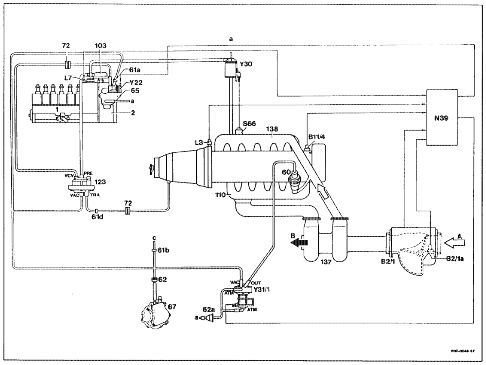
Engine 603.970 Gs), Model Year 1990 EDS control unit N39 Injection pump Switch, engine overload protection Y22 ELR actuator Switch-over valve, engine overload protection Y30 Vacuum transducer, exhaust gas recirculating Y31/1 valve
Fresh air flow to car interior Bros Other ancillaries Intake air Exhaust air
Pressure and vacuum connections at vacuum transducer or vacuum amplifier Exhaust gas turbocharger Charge air distribution pipe PRE Charge pressure from ALDA unit Air flow sensor potentiometer with intake air To vacuum unit of automatic transmission VAG temperature sensor, EDS Vacuum from vacuum pump vcv Intake air temperature sensor To vacuum control valve EDS coolant temperature sensor ATM Fresh air flow to car interior OUT Engine speed sensor, starter ring gear Exhaust gas recirculation to exhaust gas Control rod travel sensor recirculating valve or recirculating air valve
epitin =RA 07.1.1032-0010/49
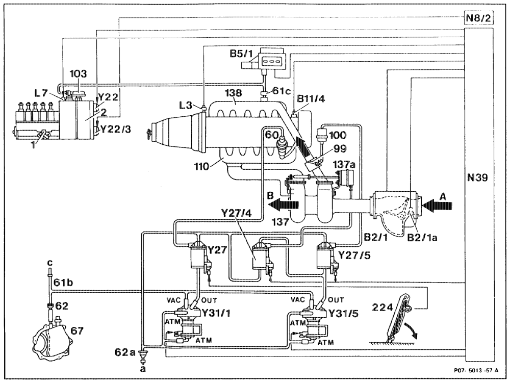
Engine 602.96 with manual transmission, Basic Version Code 62/0 as of 06/91, CA GN) Model Year 1992
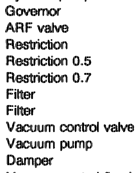
Injection pump Y22 ELR actuator 3° Governor Y22/3 ARA actuator Y27 ARF switchover valve ARF valve Restriction 0.5 Ve74 Boost pressure control switchover valve Restriction 0.7 Y275 Vacuum control flap switchover valve Y3W ARF pressure transducer Fitter Y3US Pressure transducer, boost pressure Fitter Vacuum pump contro/vacuum control flap Vacuum coritrol flap in mixing housing Intake air Vacuum unit, vacuum control flap o> oo ALDA unit Exhaust air Exhaust manifold Fresh air to car interior Other components Exhaust gas turbocharger Vacuum unit, boost pressure control valve 137a Charge air distribution pipe Pressure and vacuum connections at 138 Accelerator pedal vacuum transducers 224 Bast Air flow sensor potentiometer VAC Vacuum from vacuum pump Bala Intake air temperature sensor ATM Fresh air flow to car interior EDS pressure sensor OUT Qutlet from pressure transducer (Y31/1) to BS/1 EDS coolant temperature sensor switchover valve (27) (exhaust gas Biii4 Engine speed sensor, starter ring gear recirculation) OUT Control rod travel sensor Outlet from pressure transducer (31/5) to the L7 switchover valves (Y27/4) and (27/5) ARA control unit N&/2. EDS control unit N39
utiim = RA 07.1.1032-0010/50
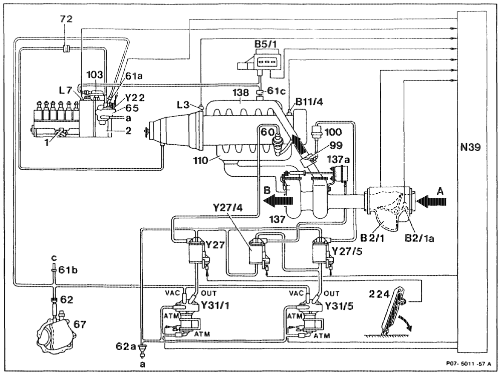
Engine 602.96 with automatic transmission, Basic Version Code 62/0 as of 06/91, CAD Gin) GD Ge) Gs) Model Year 1992
Control rod travel sensor L7 Injection pump 1 EDS control unit N39 2 Y¥22 ELR actuator 60 Y27 ARF switchover valve 61a Y27/4 Boost pressure control switchover valve 61b Y275 Vacuum control flap switchover valve 6ic Y3IA ARF vacuum transducer Y3VS Vacuum transducer, boost pressure 62a contol/vacuum contro! flap 67 O> or Intake air 72 Exhaust air Vacuum control flap in mixing housing Fresh air flaw to car interior Vacuum unit, control flap vacuum unit 100 Other components ALDA unit 103 Exhaust manifold 110 Exhaust gas turbocharger Pressure and vacuurn connections at 137 Vacuum unit, boost pressure contro! valve 1374 vacuum transducers Charge air distrioution pipe VAC Vacuum from vacuum pump 138 Accelerator pedal ATM Fresh air flow to car interior OUT Outiet from vacuurn transducer (¥31/1) to Bat Air flow sensor potentiometer Intake air temperature sensor switchover vatve (Y27) (exhaust gas Baia EDS pressure sensor recirculation) BS/1 OUT EDS coolant temperature sensor Outiet from vacuum transducer (¥31/5) to the B14 Engine speed sensor, starter ring gear switchover valves (Y27/4) and (Y27/5)
oii RA 07.1.1032-0010/51
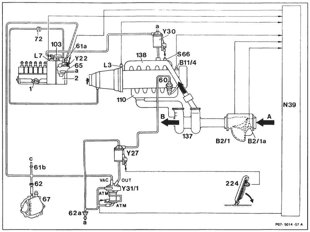
Engine 603.96, Basic Version Code 62/0 as of 06/91, (> Git) GD Model Year 1992
Control rod travel sensor
1 Injection pump L7 EDS control unit
2 Govemor
60 ARF valve Engine overload protaction switch ELR actuator 61a Restriction ARF switchover valve 61b Restriction 0.5
62 Filter Engine overload protection switchover valve ARF vacuum transducer 62a Fitter
65 Vacuum control valve Intake air
67 Vacuum pump Exhaust air
72 Damper Fresh air flow to car interior 103 ALDA unit Other components 110 Exhaust manifold 137 Exhaust gas turbocharger 138 Charge air distribution pipe Pressure and vacuum connections at 224 Accelerator pedal vacuum transducers Bat Air mass sensor potentiometer VAG Vacuum from vacuum pump Baia Intake air temperature sensor ATM Fresh air flow to car interior Bi1/4 EDS coolant temperature sensor OUT Outlet from vacuum transducer (¥31/1) to
3 Engine speed sensor, starter ring gear switchover valve (Y27) (exhaust gas recirculation)
hin =RA 07.1.1032-0010/52
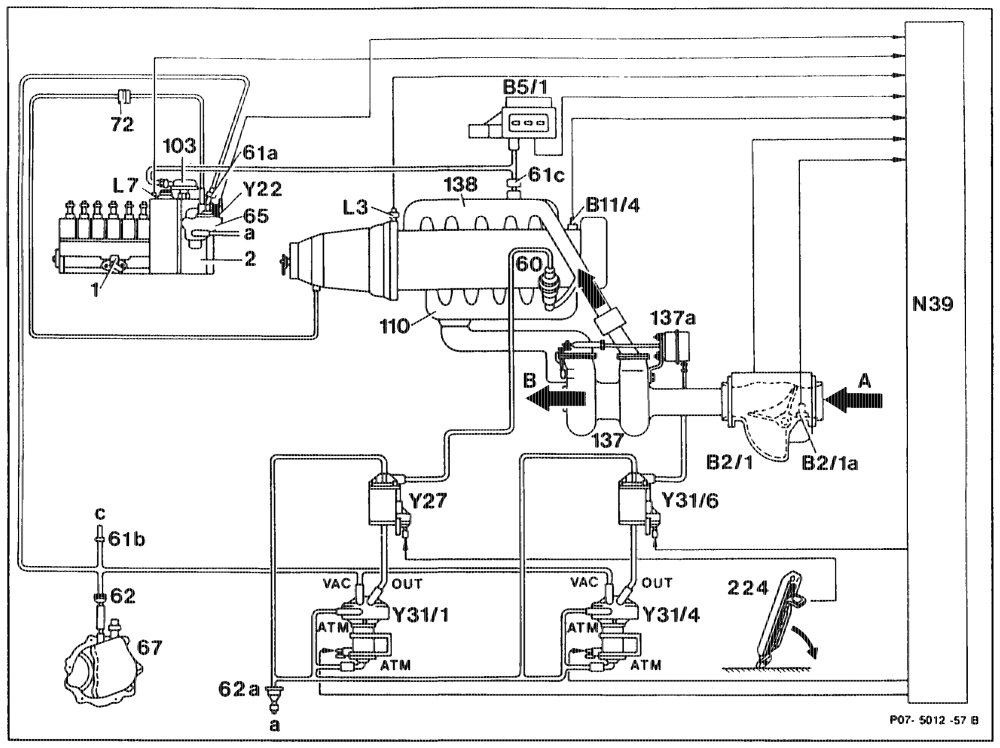
Engine 603.971 base version Code 62/0, G4, model year 1992 EDS control unit Injection pump N39 Y22 ELR actuator Ye7 ARF switchover valve YS Exhaust gas recirculation valve vacuum transducer Y31/4 Boost pressure control vacuurn transducer Y31/6 Boost pressure cutoff switchover valve Fitter Vacuum control valve ono, Intake air Vacuum pump Exhaust air Damper Fresh air flow to car interior Other components ALDA unit Exhaust manifold Exhaust gas turbocharger Pressure and vacuum connections at Vacuurn unit, boost pressure control valve vacuum transducers Charge air distribution pipe VAG Vacuum from vacuum pump Accelerator pedal ATM Fresh air flow to car interior Air mass sensor potentiometer OUT Outlet from vacuum transducer (¥31/1) to Intake air temperature sensor switchover valve (Y27) (exhaust gas EDS pressure sensor recirculation) OUT EDS coolant temperature sensor Outlet from vacuum transducer (Y31/4) to Engine speed sensor, starter ring gear switchover valve (Y31/6) or to vacuum unit, Control rod travel sensor boost pressure control valve (1374)
gdm = RA 07.1.1044-0010/53
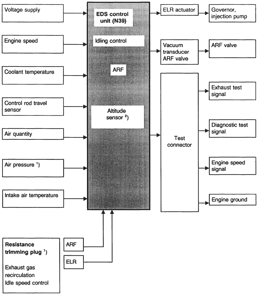
d) Influencing variables of electronic diesel system (EDS) Engines 602.96 and 603.96 up to Model Year 1991
1) Model Year 1986/87 only 2) Effective Model Year 1988 integrated in control unit.
oti = RA 07.1.1032-0010/54
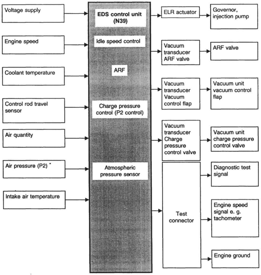
Engine 602.96 (cH) CX) Model Year 1991 Model Years 1990, 1991
Pressure upstream of inlet valves
antiis = RA 07.1.1032-0010/55
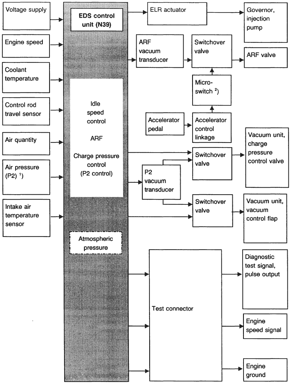
62/0 as of 06/91 )as of Model Year 1992
1) Pressure upstream of inlet valves. 2) Switchover valve is actuated by microswitch of accelerator control 10° before full load.
uti = RA 07.1.1032-0010/56
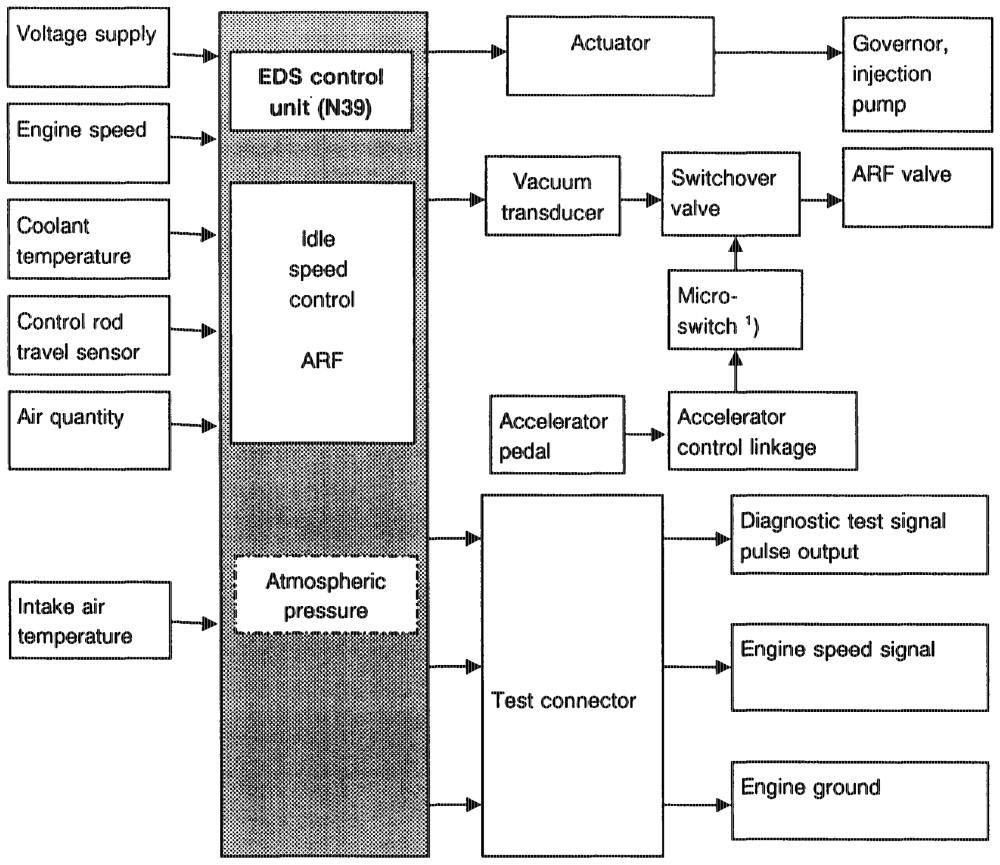
Engine 603.96 Basic Version Code 62/0 as of 06/91 CD Git) GD as of Model Year 1992
1) The switchover valve is actuated by the microswitch of the accelerator control 10° before full load.
eptihigm = RA 07.1.1032-0010/57
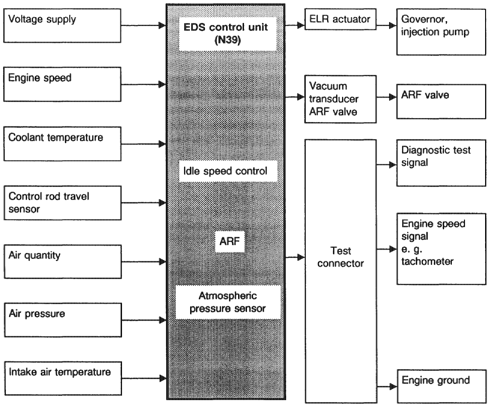
E ngine 603.970 @4) Model Year 1990 only see
otis =RA 07.1.1032-0010/58
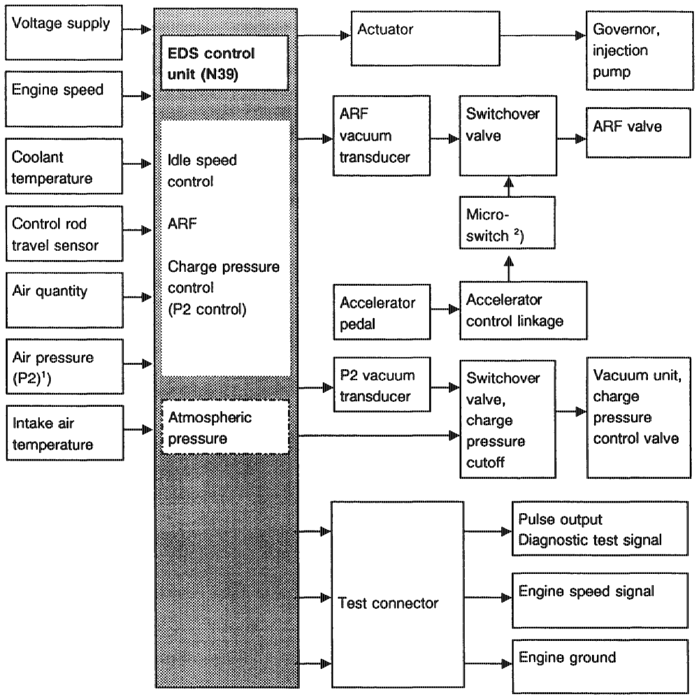
Engine 603.971 Base version Code 62/0, Gs) as of model year 1992
’) Pressure upstream of inlet vatves. 2) The switchover valve is actuated by the microswitch of the accelerator control 10° before full load.
pti = RA 07.1.1044-0010/59 e) Electronic idle speed contro! (ELR) The engine speed sensor detects the engine speed (144 pulses/revolution) and passes it on to the EDS control unit in the form of an alternating voltage. The EDS control unit processes the engine speed signal and performs the set value/actual value comparison. This enables idling speed to be maintained at a constant level by the actuator irrespective of engine load. Set idling speed is raised in accordance with a fixed characteristic curve by the temperature sensor at coolant temperatures < 60 °C.
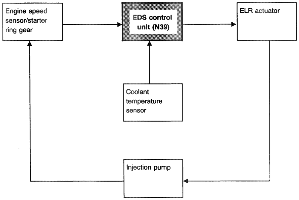
Block diagram of idle speed control (ELR)
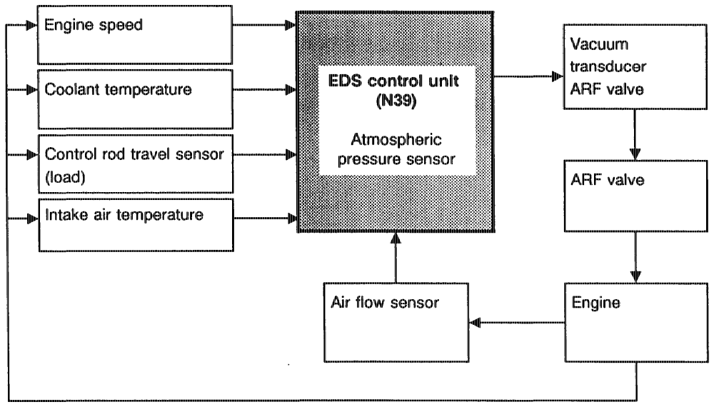
otiiiy §=RA 07.1.1032-0010/60 f) Exhaust gas recirculation (ARF) The ARF quantity is reduced as engine load and Exhaust gas recirculation is initiated as soon as speed increase. This means the following conditions are met: Increase in the control current = increase in ARF ® Coolant temperature between 60 °C and quantity. 110 °C Reduction in control current = reduction in ARF ® Engine speed between idle and 2800/min or quantity. 3500/min on Engine 602.96 12 from Model Additionally as of Model Year 1992: ARF sey Year 1990 Gsa) shutoff at 10° before full load by means of @ Engine speed up to approx. 3500/min as of microswitch of accelerator control and Model year 1992, Engines 602.96, 603.96 switchover valve in vacuum line. This reduces smoke emissions during load change in full load and 603.971 ® Control rod travel less than 9 mm direction. ® Battery voltage 11–14 Voit
Note Depending on the input signals of the sensors Temperature and engine speed are dependent e.g. control rod travel, engine speed etc., the on the control unit version. Refer to test routine IS control unit determines the matching for exact data. £ c quantity of recirculated exhaust gas for each operating state. The vacuum transducer is energized and supplies the corresponding vacuum to the ARF valve.
ram ARF up to Model Year 1991 (inclusive)
Block d
pttiijn = RA 07.1.1032-0010/61
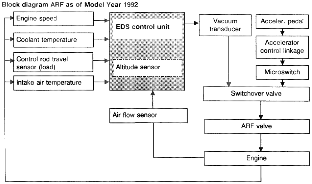
The ARF system with vacuum transducer, switchover valve (as of Model Year 1992), ARF co valve, air flow sensor and EDS control unit operates as a closed control loop.
within =RA 07.1.1032-0010/62 g) Recirculating air control for trap oxidizer (GA California Engine 603.96 Model Year 1986/87 only)
In order to achieve more favourable combustion conditions for the trap oxidizer, the recirculating air valve is continuously opened or closed cording to a performance characteristic map.
Following the closing operation, a residual vacuum of approx. 30 mbar is retained at the recirculating air valve. The recirculating air valve is open between 1000 and 3400/min. The control rod travel must be <9 mm.
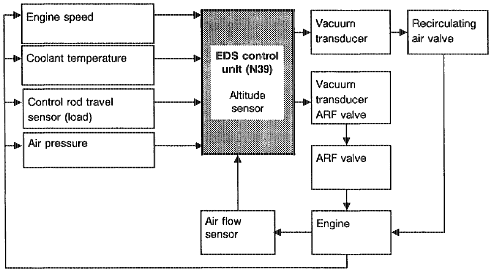
Block diagram recirculating air control
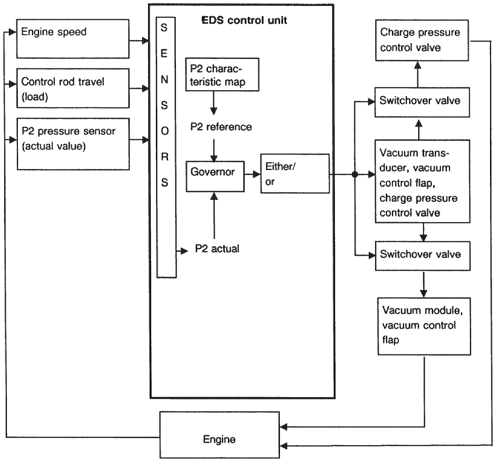
ephin =RA 07.1.1032-0010/63 h) Charge pressure control (P2 control) Engine 602.96 Basic Version Code 62/0 as of 06/91 as of Model Year 1990 CH) as of Model Year 1991 C2 GN) as of Model Year 1992 Engine 603.971 Base version Code 62/0 GS as of model year 1992
A „characteristic map” (P2 control) is stored in the EDS control unit. The pressure values obtained as a function of injection quantity and engine speed produce an optimum engine operation in respect of performance, NO,, HC and particle emissions.
Function Particle emissions are lowered by reducing the pressure (P2) in front of the inlet valves under part load conditions.
A control circuit exists in the EDS control unit through which a pressure comparison of ”P2 actual” and ”P2 reference” is performed (refer to block diagram).
Any pressure difference is compensated for by the charge pressure control valve or by the pressure control flap. These pressure actuators are operated by the vacuum transducers by means of an electronically adjustable vacuum.
Charge pressure control is dependent on: ® Coolant temperature (up to 1991) Intake air temperature (up to 1991) ® Intake air pressure (pressure upstream of inlet valves) ® Engine speed Position of control rod (control rod travel)
gttiny = RA 07.1.1044-0010/64
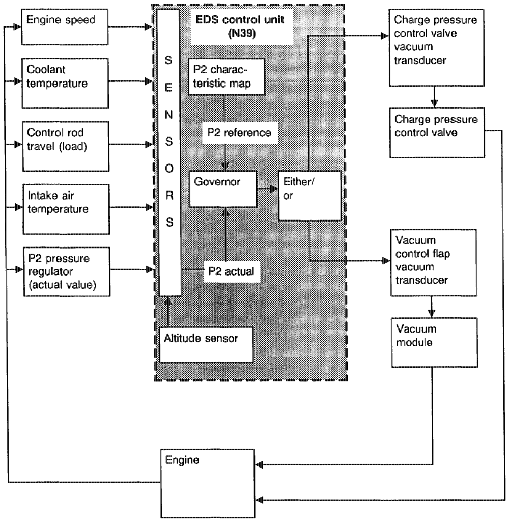
Block diagram charge pressure control (P2 control), Engine 602.962 Model Year 1990 CG) Model Year 1991
ewtihija =RA 07.1.1032-0010/65
gtitim = RA 07.1.1032-0010/66
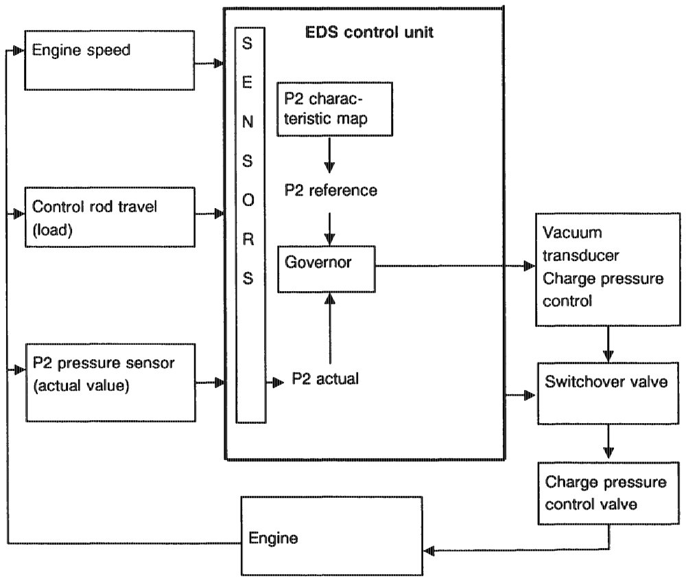
Block diagram boost pressure control! (P2 control), engine 603.971 Base version Code 62/0 as of model year 1992
eptihipn = RA 07.1.1044-0010/67 i) System diagnostics
With the self-test program integrated in the EDS sontrol unit, the „electronic diesel system” can be checked and faults recorded and stored. Temporary faults of more than 4 seconds duration are also memorized. E.g. sensor faults with the exception of speed sensors are memorised, as well as short-circuits in the actuators or their lines. The pulse display can be tapped via the tes connector (X11/4), socket 4 and the individual faults evaluated with the aid of a pulse counter. Depending on the readout, the defective component or its leads can be determined.
Model Year 1986/87 C1) Gsa)
=DS control unit with fault detection. Only perrnanently occurring faults are detected.
Model Year 1988 CG Basic Version Code 6 as of 06/91 (of Am 2, CAD Ga) GD) 1K) GO As of Model Year 1992 (sa) a
EDS control unit with fault memory. Intermittently occurring faults are also stored.
apie = RA 07.1.1032-0010/68
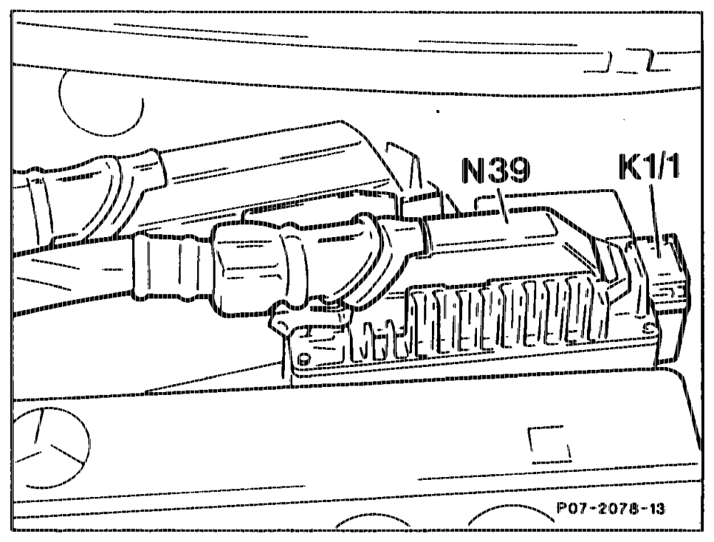
j) Location and function of components
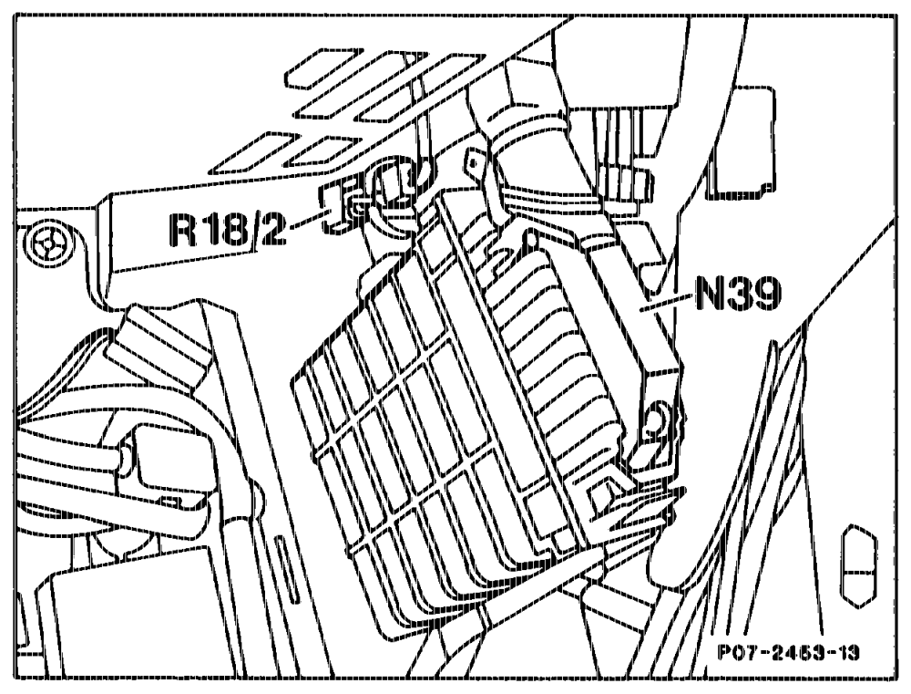
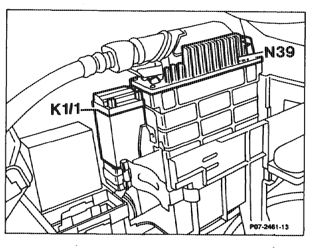
EDS control unit (N39) The control unit processes the incoming signals and supplies a current (mA) to the vacuum transducers, switchover valves, as well as to the actuator of the injection pump. The entire signal can be checked with the pulse counter by means of a signal, or the fault memory read via an outlet which runs to the test coupling (92) or (X11/4).
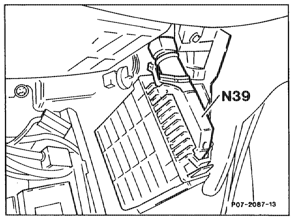
Model 126 in right footweill behind side panelling
Model 126.13 (Engine 603.970) Installed on right in interior
auhis = RA 07.1.1032-0010/69
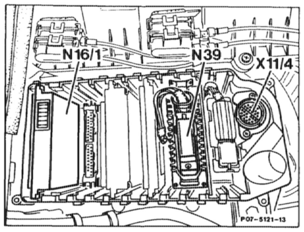
Model 140 Engine 603.971
Mode! 201 behind battery in component compartment
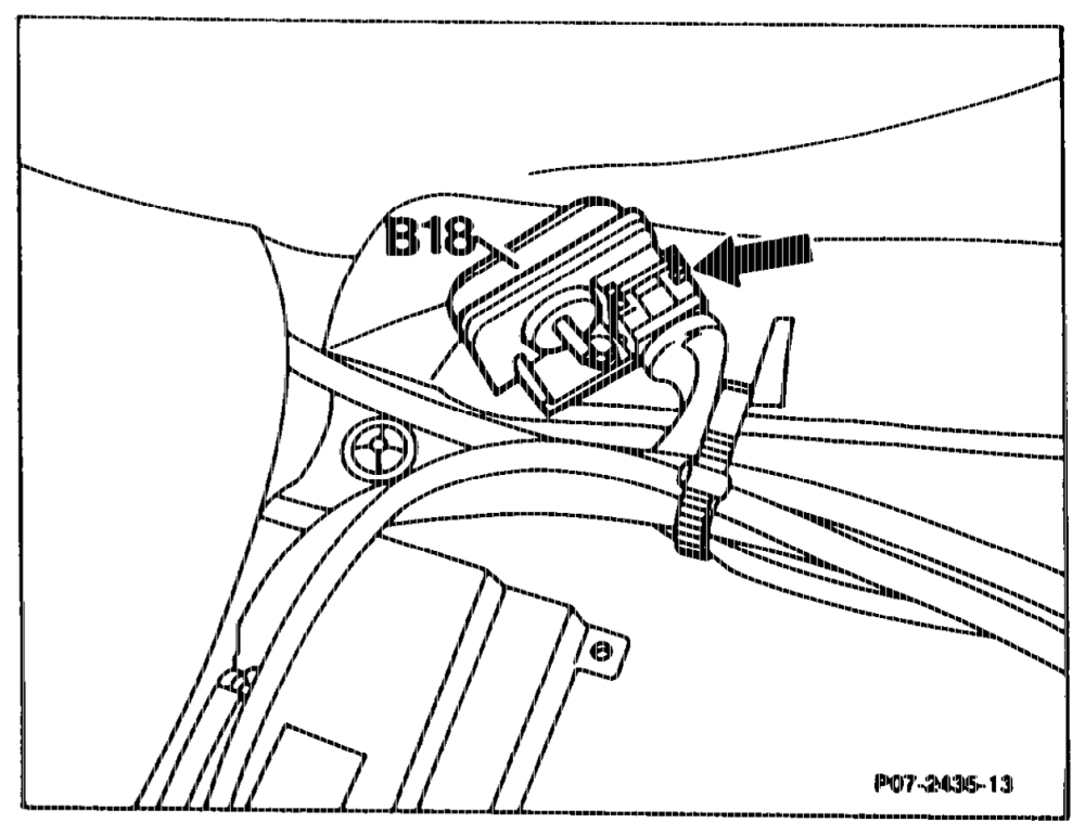
Altitu ade » sensor (Bi 1 8)
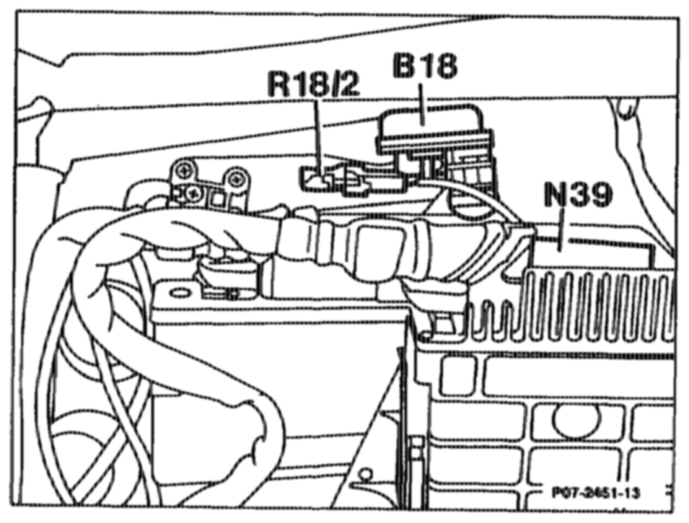
The quan tity of recirc ulated exhaust gas is influenced by the atmospheric pressure sensor as a function of altitude or air pressure. The altitude sensor supplies a voltage signal to the control unit which drops ir pressure drops (increasing altitude). The control unit matches the quantity of exhaust gas recirculated to the respective air pressure by reducing the vacuum transducer current.
Models 124, 201 in component compartment
oii = RA 07.1.1032-0010/70
Model 126 in right footwel!
Altitude sensor (integrated In control unit) CA) CD Gk) Gin) GSA) as Of Model Year 1990 Basic Equipment Code 62/0 as of 06/91 ©) as of Model Year 1992 The quantity of recirculated exhaust gas is influenced by the atmospheric pressure sensor as a function of altitude or air pressure. The atmospheric pressure sensor supplies a voltage signal to the control unit which is proportional to air pressure (i. e. low voltage with low air pressure). The control unit matches the quantity of exhaust gas recirculated to the respective air pressure by reducing the vacuum transducer current.
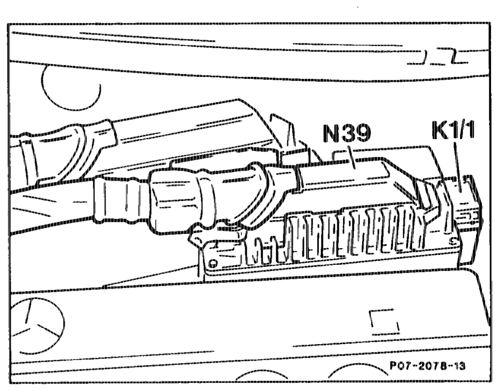
Overvoltage protection (K1 or K1/1) The power for the electronic control units is supplied through the overvoltage protection relay.
Models 124, 201 behind battery in component compartment
ptiiyn = RA 07.1.1032-0010/71
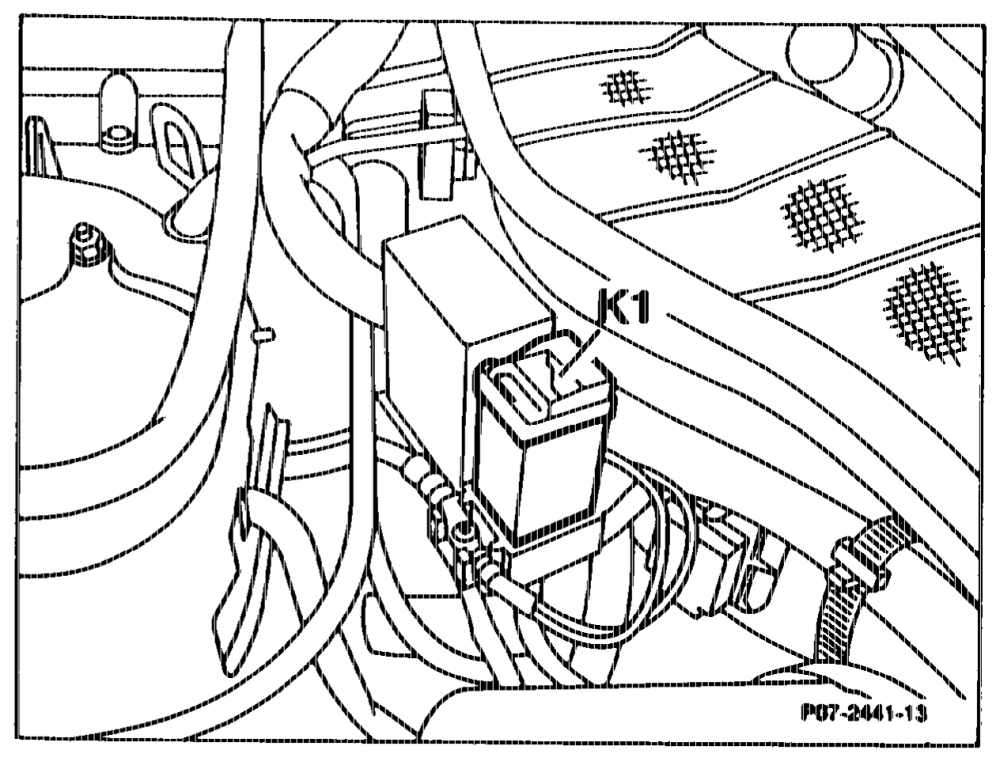
and 30a. The fault memory is energized through terminal 30a. When the ignition is switched on, the relays are actuated through terminal 15 by an electronic unit. The EDS control unit is thus energized through terminal 87E and other ancillaries through terminal 87. The overvoltage protection is achieved by means of a 22 volts Zener diode. Voltage peaks in excess of 22 volts occurring upstream of the overvoltage protection are switched directly to ground by the Zener diode. An overload is prevented by a fuse. Terminals 87E and 87L are protected separately. Monel 126 in component compartment next to ABS control
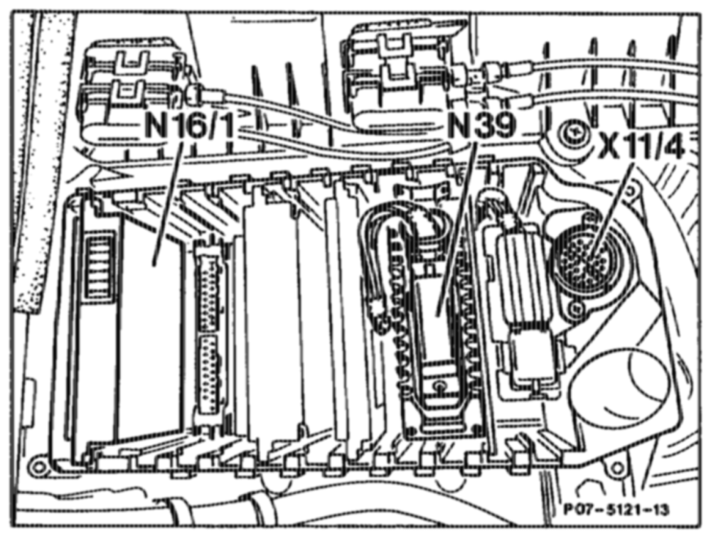
Base module (N16/1) Engine 603.971, Model 140 base version Code 62/0, GA as of model year 1992 The base module (N16/1) performs the function of the overvoltage protection relay.
eptitin = RA 07.1.1044-0010/72
Test coupling (X92) or (X11/4)
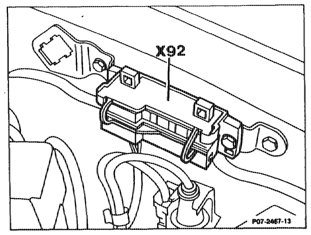
Test coupling (X92) CE Model Year 1986/87 The diagnostic test signal can be tapped via the test coupling.
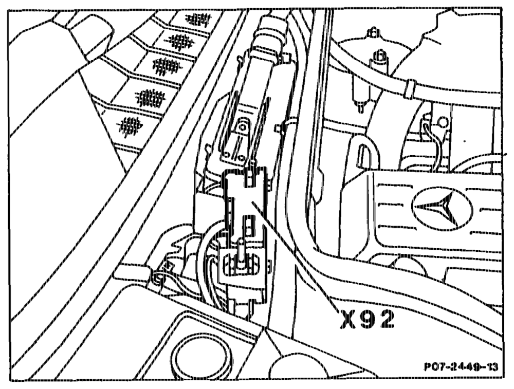
Model 124 and 201 in right of component compartment
Model 126
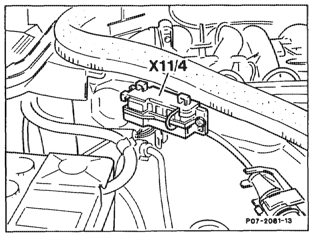
Test coupling (11/4) The pulse readout for the diagnosis of the EDS can be tapped via test coupling, contact 4.
Model 124, 201
tii = RA 07.1.1032-0010/73
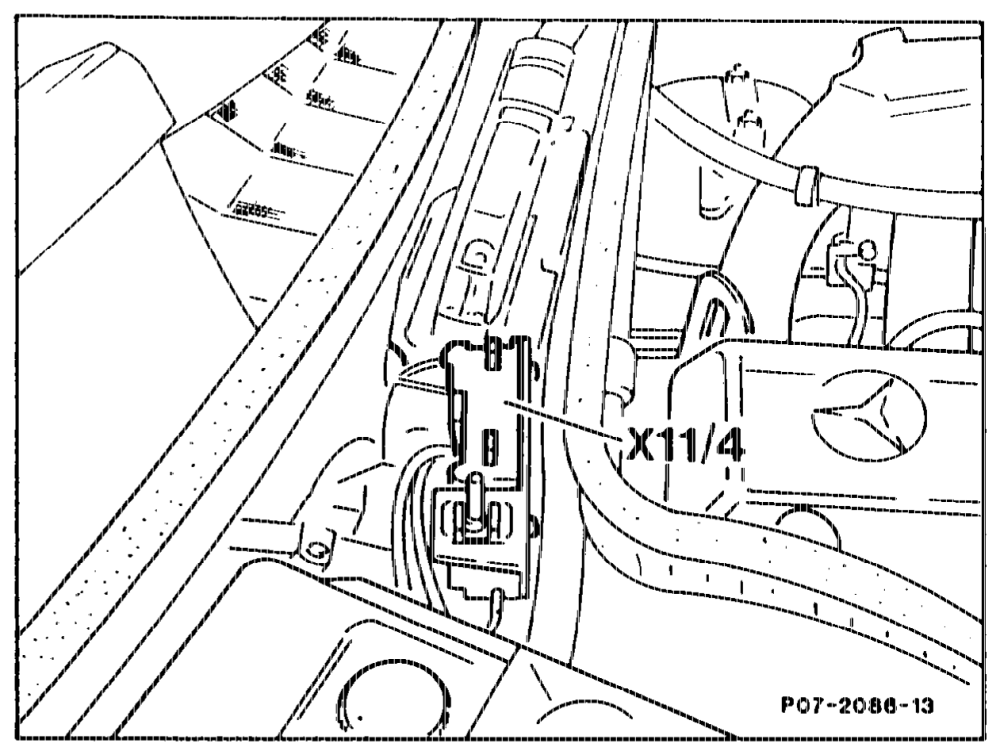
Model 126
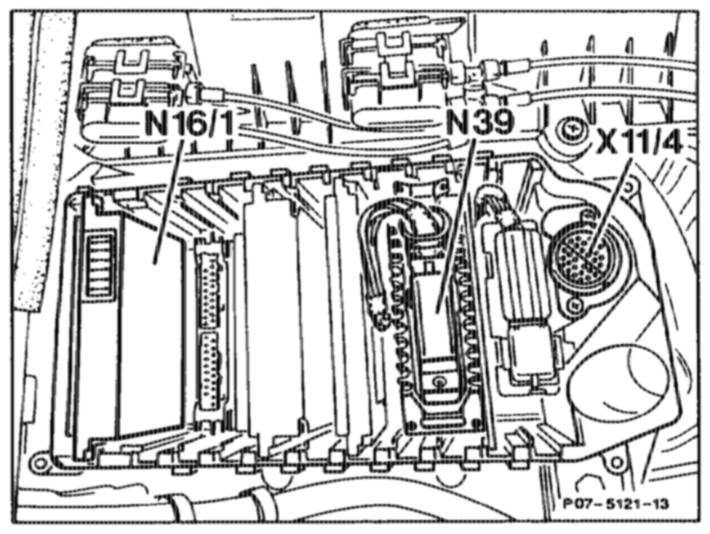
Test coupling (X11/4) integrated in module box Model 140 Gs) Model Year 1992 The pulse readout for diagnosis can be tapped at contact 4 of the 38-pin test coupling.
Model 140
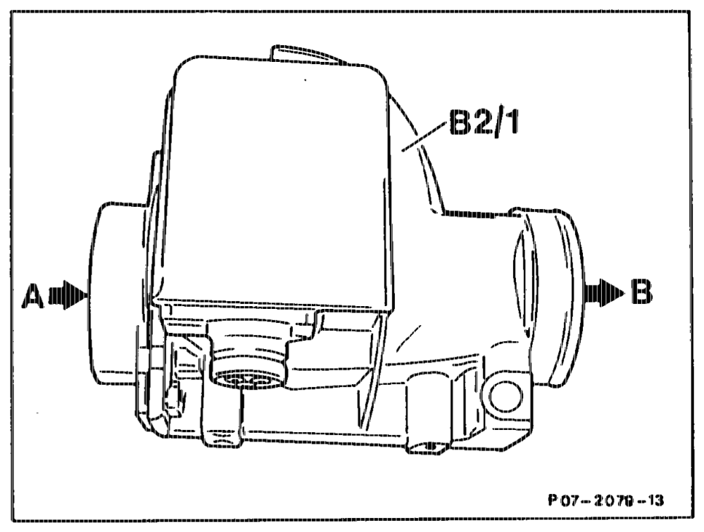
Alr flow sensor potentiometer (B2/1) Fitted in the air flow between air filter and exhaust gas turbocharger.
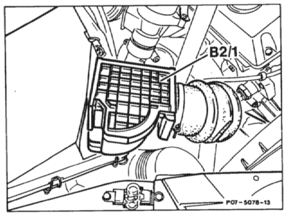
A from air filter B to exhaust gas turbocharger
Model 140
otis = RA 07.1.1032-0010/74
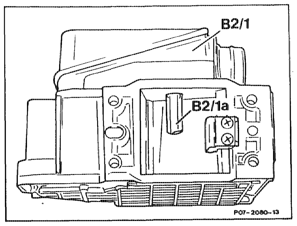
The intake air deflects the air flow sensor flap against the restoring force of a spring into a defined angular position. The position is measured by means of a potentiometer, and converted into a voltage ake air temperature is detected by a ature sensor (B2/1a) in the air flow ( sensor.
Air flow sensor Model 201 without round flange
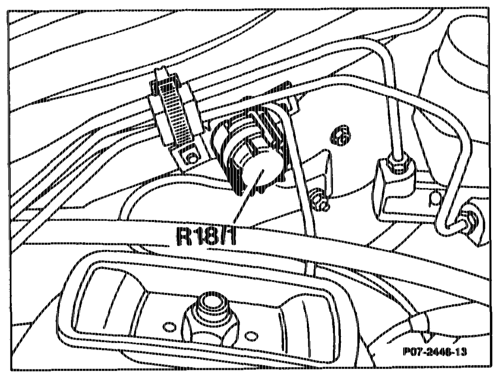
sistance trimming plug (R181) for idling speed Model Year 1986, 1987, 1988 For setting the idling speed. Specification: 630 + 20/min.
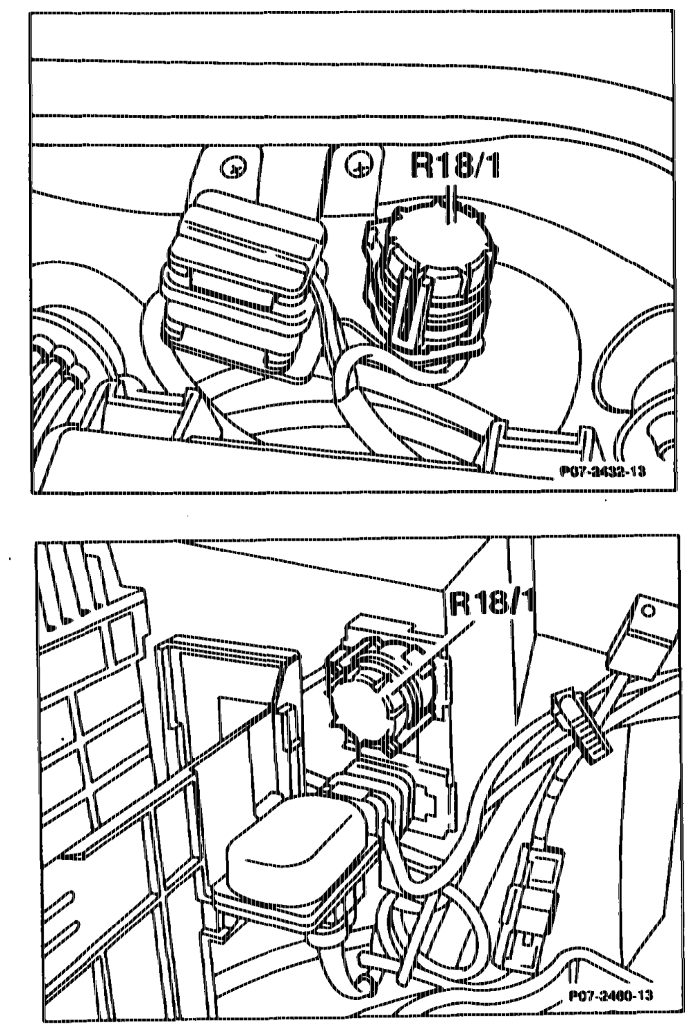
Model 124
Model 126
Model 201
eotihim = RA 07.1.1032-0010/75
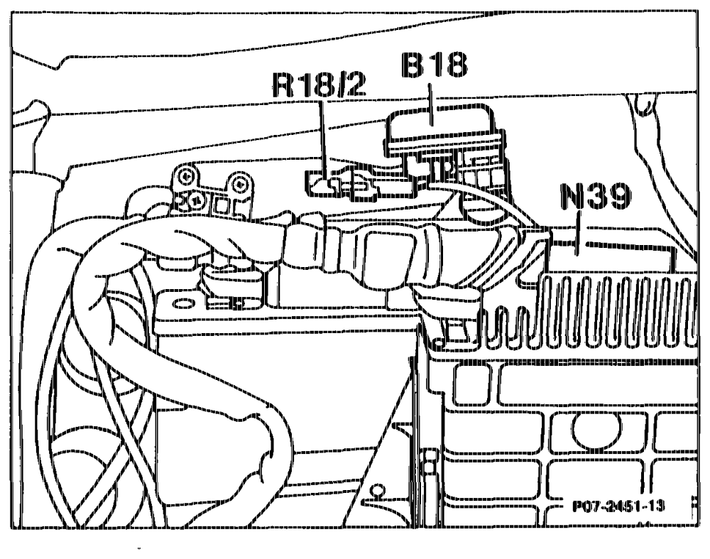
nce resistor (R18/2) for exhaust gas Refere ation, Model Year 1986, 1987, 1988 recir
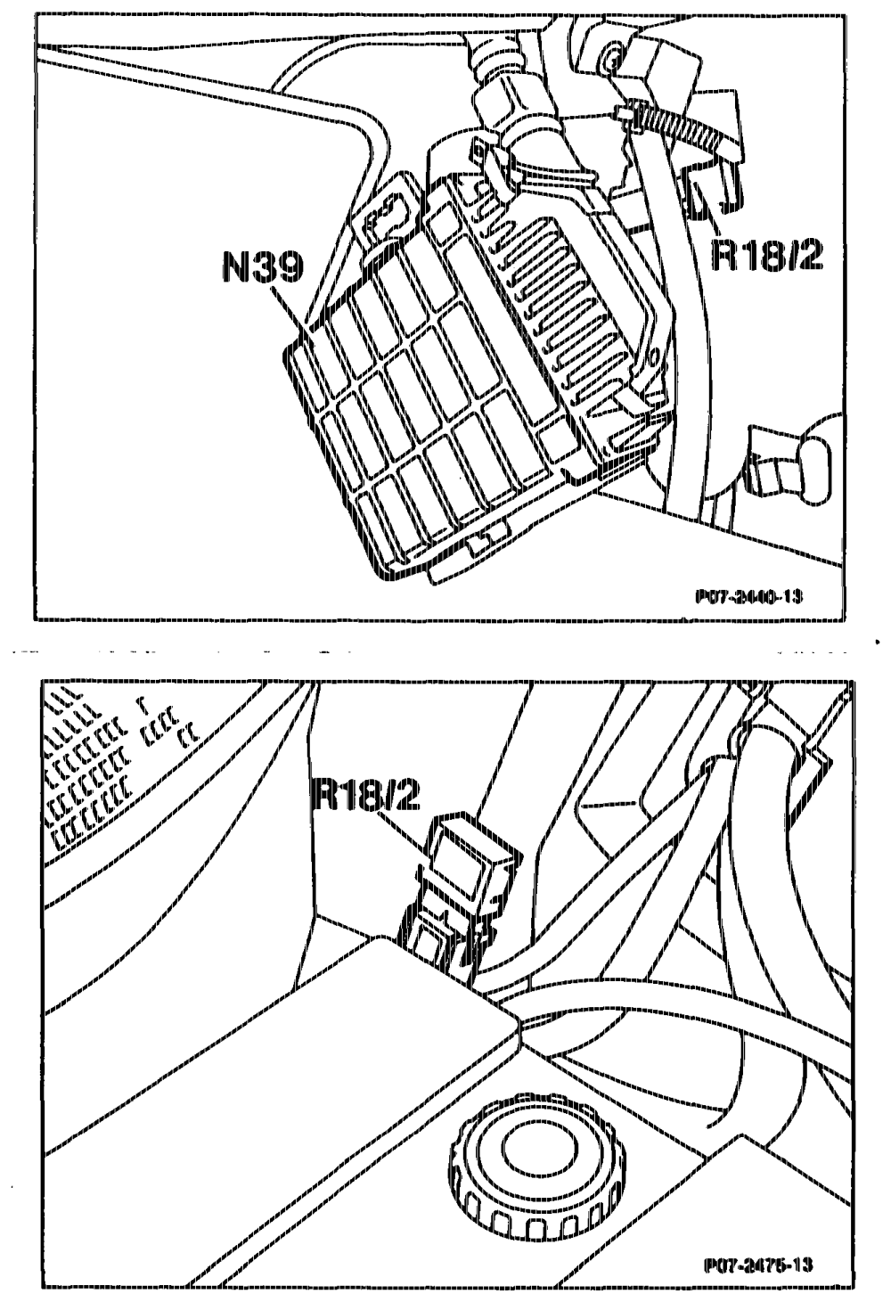
Model 124 in components compartment
Model 126 at right of car interior next to control unit (N39)
Model 201 in component compartment next to battery
gttiiyn = RA O7.1.1032-0010/76
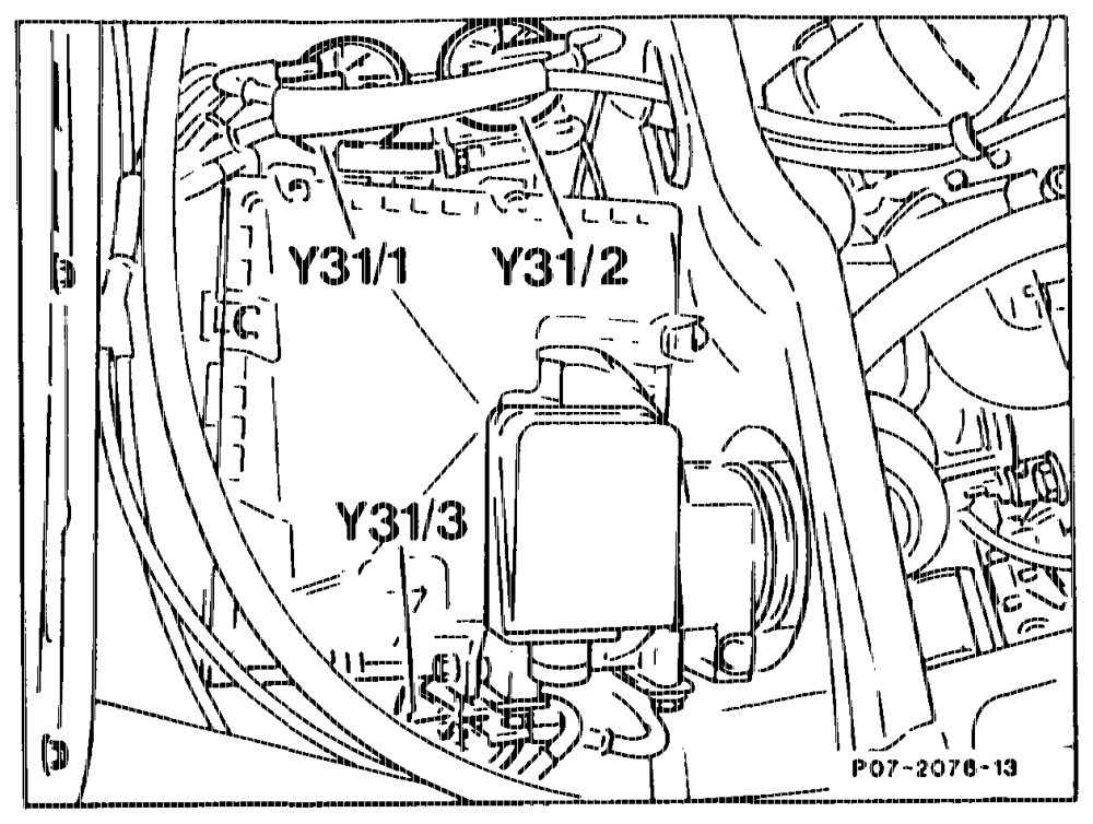
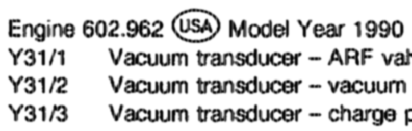
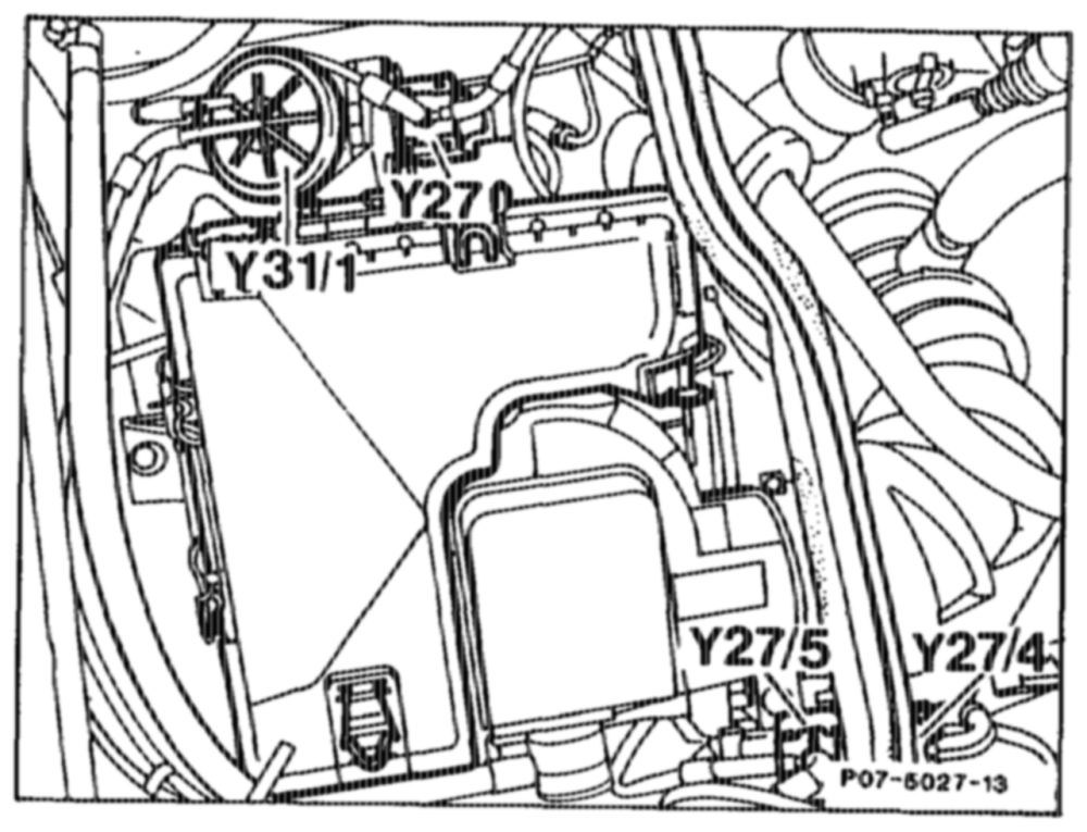
Vacuum transducer (¥31/1, ¥31/2, ¥31/3) up to Model Year 1991 Vacuum transducer (Y¥31/1, Y31/4, ¥31/5) as of Model Year 1992 The vacuum transducers are supplied with a control current as an input signal from the control unit depending on the operating state. The vacuum transducer then supplies the appropriate vacuum for the actuators. As of model year 1992 the vacuum is transmitted from the vacuum transducers through electrical switchover valves to the ARF valve and to the vacuum unit of the vacuum control flap or charge pressure control.
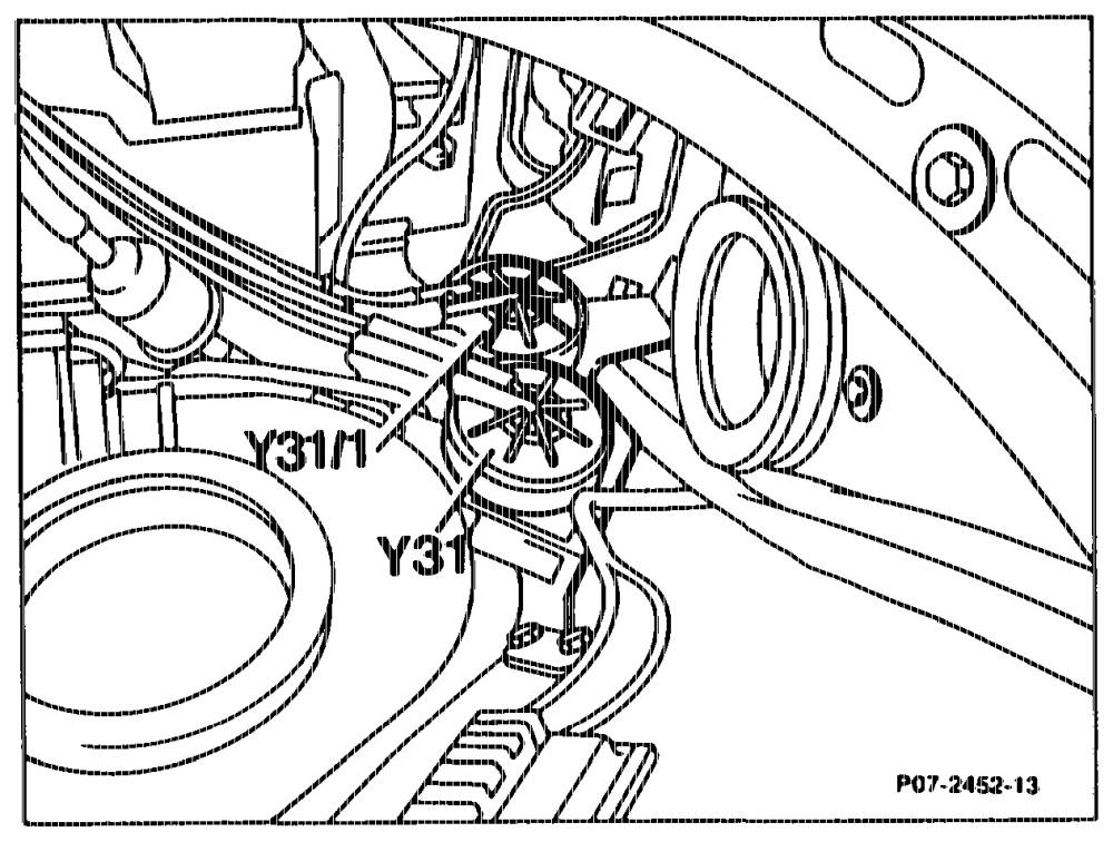
control flap pressure control
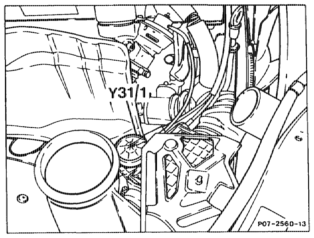
Engine 603.96 in Mode! 124
Engine 603.96/97 in Model 126 Y31/1 Vacuum transducer ARF valve
emia = RA 07.1.1032-0010/77
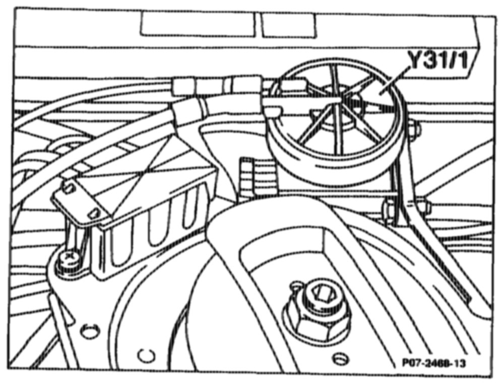
Engine 602.96 in Model 201
Engine 602.96 Model 124 Bas sic Ve ersion Code e & 10 as of 06/91 Ca) Gin) GSA) as of Model Year 1992
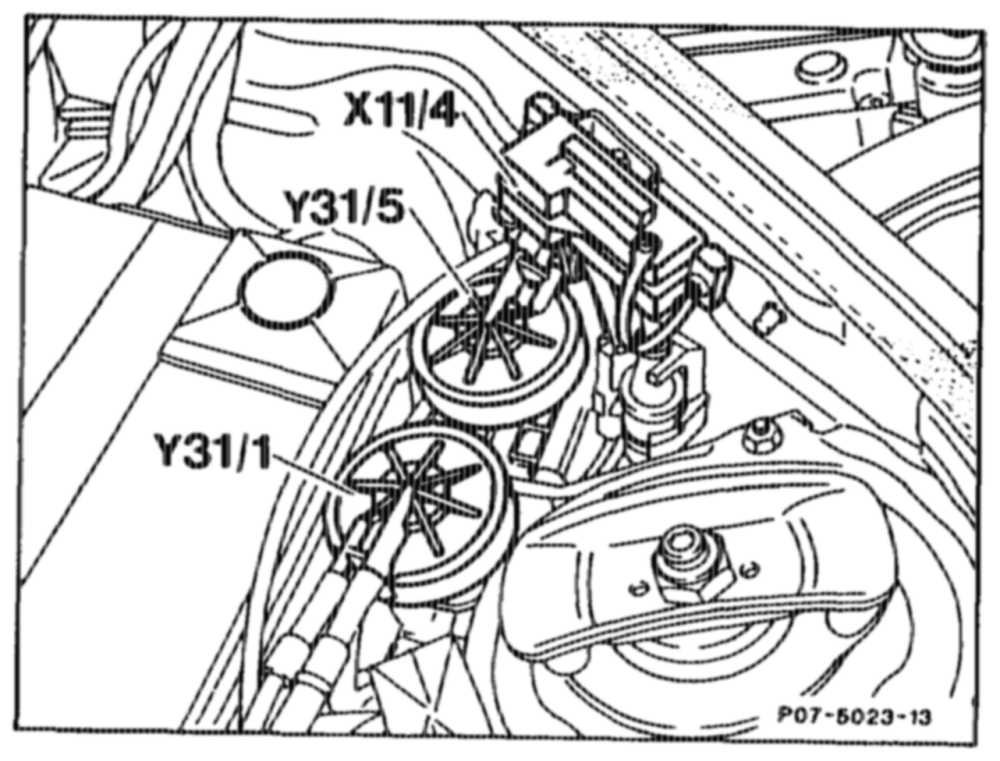
Y31/1 Vacuum transducer ARF valve Y31/5 Vacuum transducer charge pressure contro/vacuum control flap (not visible fitted below air filter)
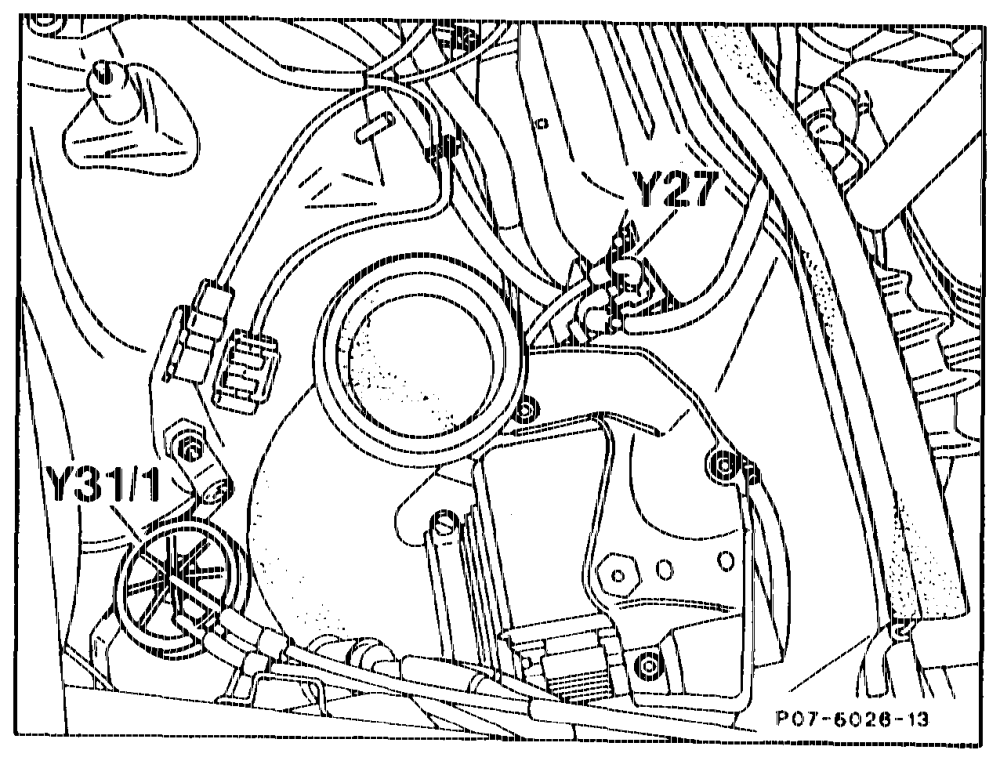
Engine 602.96 Made! 201 Basic Version Code 62/0 as of 06/91 me CA) GN) as of Model Year 1992 Y¥31/1 Vacuum transducer ARF valve Y31/5 Vacuum transducer charge pressure controvvacuum control flap
Engine 603.96 Model 124 E > Ver sion Code 62/0 as of 06/91 Cin) C5) as of Model Year 1992 oe Y27 ARI hover valve Y¥31/1 Vacuum transducer, ARF valve
«myn ~~ RA 07.1.1032-0010/78
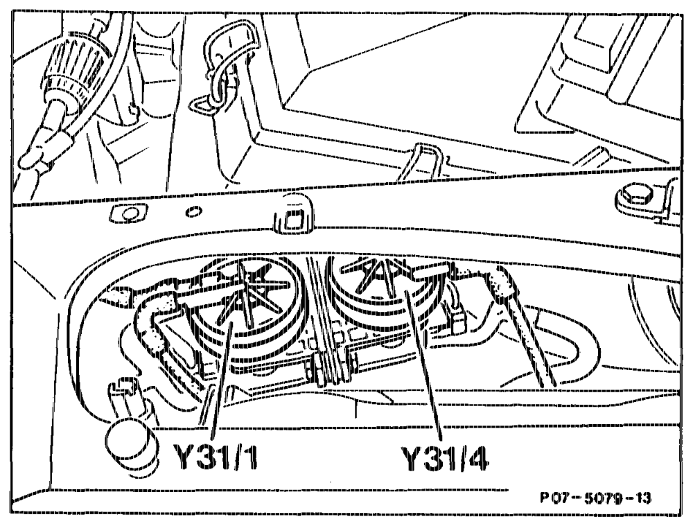
Engine 603.971 Mode! 140 Base version Code 62/0 Pon (USA) as of model year 1992 Y31/1 Vacuum transducer ARF valve Y31/4 Vacuum transducer charge pressure control
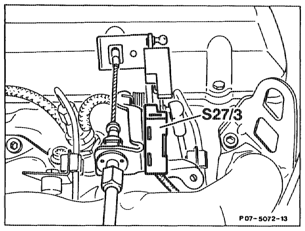
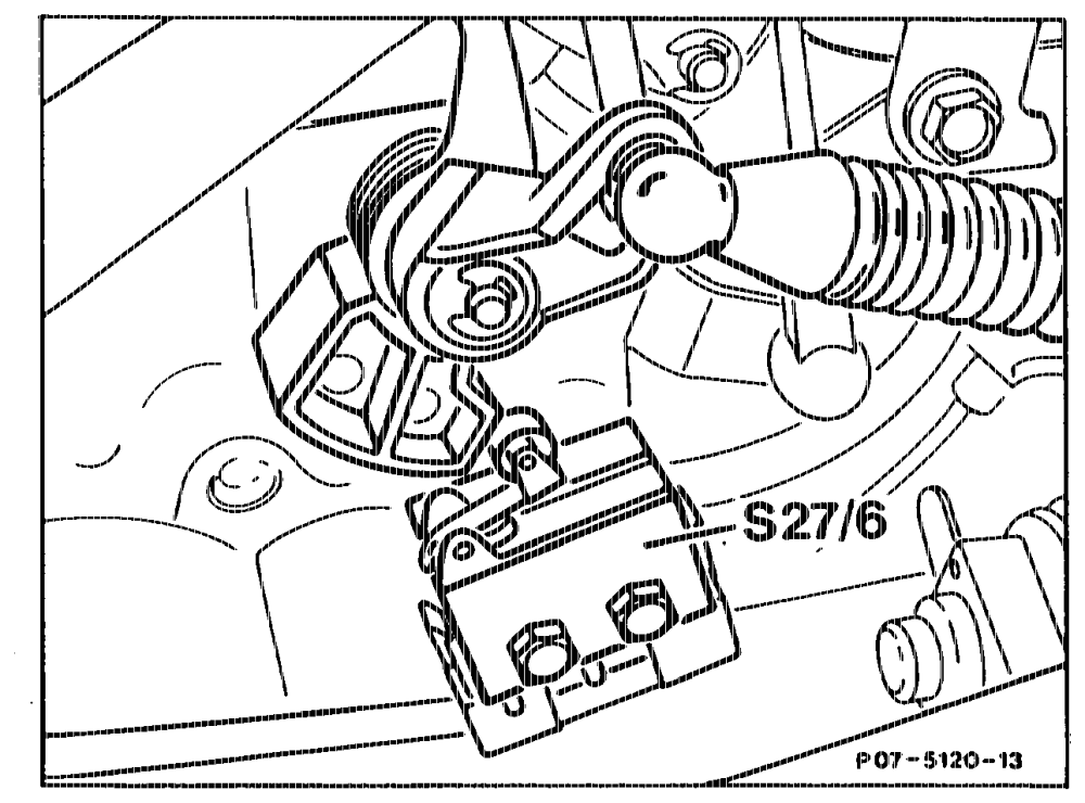
ARF electrical switchover valve (¥: ARF microswitch ($27/3) Basic Version Code 62/0 as of 06/91 CD) GY G) OD GD) CG as of Model Year 1992 Microswitch, compressor cutoff/ARF (S27/6) only Gs) Model 140 as of Model Year 1992 The ARF switchover valve (¥27) is actuated 10° before full load by the ARF microswitch (S27/3) of the accelerator control, or by the compressor cutoff/ARF microswitch (S27/6) of the accelerator control. This closes the ARF valve.
Note
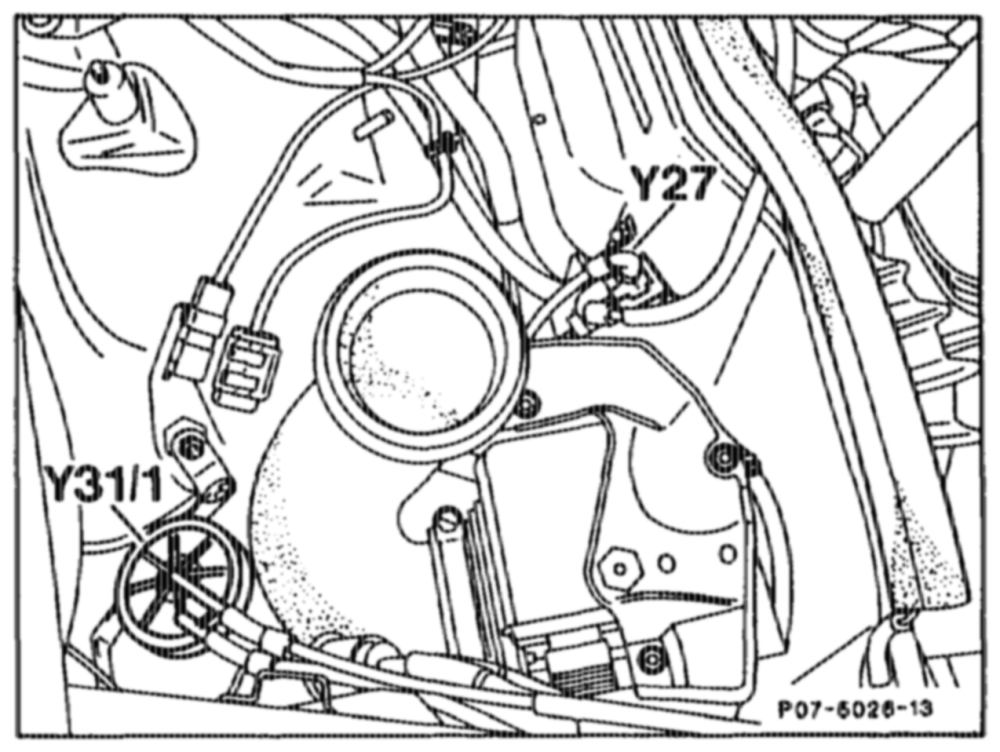
The illustration of the ARF electrical switchover valve (¥27), engine 602.96 can be found in the section „electrical switchover valves charge pressure control (Y27/4) or vacuum control flap (Y27/5)”.
Engine 603.96 Model 124 Ye7 ARF switchover valve
emia RA 07.1.1044-0010/79
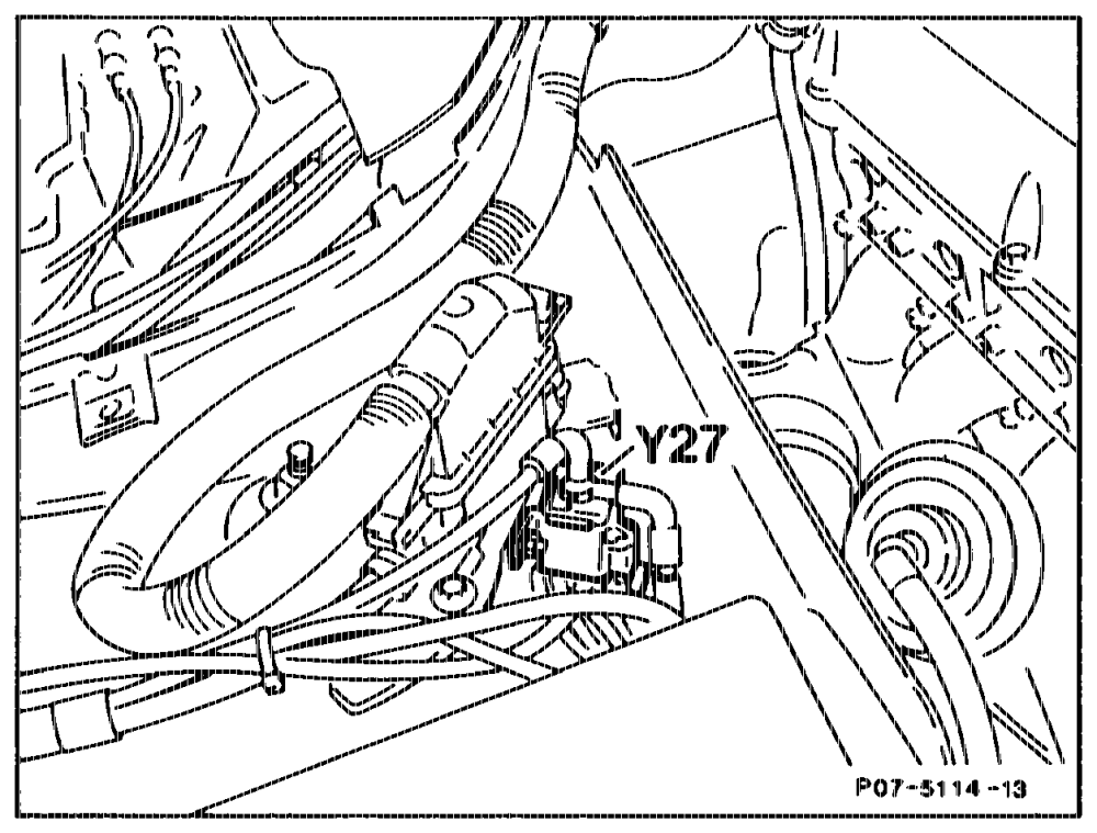
Engine 603.971 Model 140 Base eé version Code 62/0 Gsa) as of model year 1992 Y27 ARF switchover valve
Engine E 3 603.971 Model 140 Gsay as of Model Year 1992 $27/6 Compressor cutoff/ARF microswitch
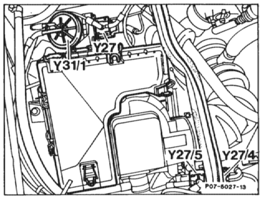
Electrical switchover valves, charge pressure control (Y27/4) or vacuum control flap (¥27/5), Engine 602.96 Basic Version Code 62/0 as of 06/91 ¢ C ) Gin) ¢ ¢ CH 1) € OK) ) sa) as of Model Year 1992 The electrical switchover valves are supplied with a control current as an input signal from the control unit depending on the operating state, and with the vacuum from the transducer. They transmit the vacuum in line with the command of the control unit to the charge pressure control valve vacuum unit or vacuum control flap vacuum unit.
Engine 602.96 Model 124 Y27 ~~ Exhe st gas recirculation switchover valve Y27/4 Charge pre re control switchover valve Y¥27/5 Vacuum control flap switchover valve
que = =RA 07.1.1044-0010/80
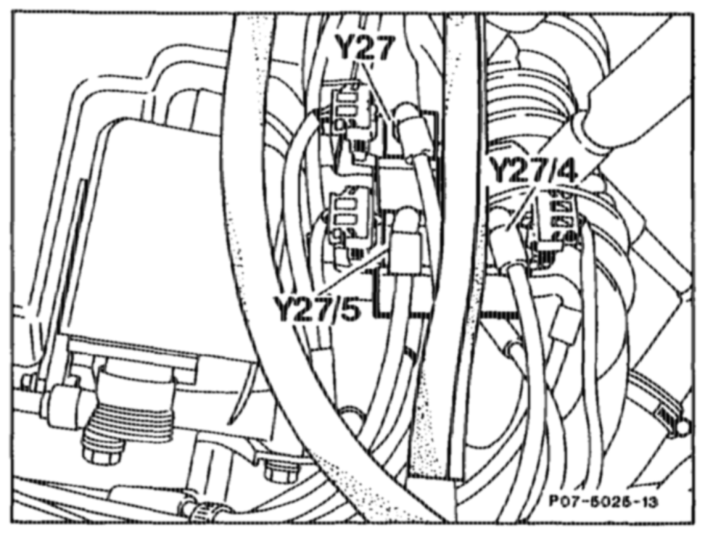
Engine 602.96 Mode! 201 Y27 Exhaust gas recirculation switchover valve Y27/4 Charge pressure control switchover valve Y27/5 Vacuum control flap switchover valve
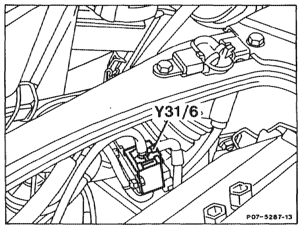
Electrical switchover valve, charge pressure cutoff (¥31/6), only Engine 603.971 Model 140 G4) Model Year 1992 If a fault occurs in the charge pressure control loop, the electrical switchover valve (Y31/6) admits air to the charge pressure control valve. Consequently, no charge pressure is built up and no turbocharger quantity is released by the injection pump.
Charge pressure cutoff switchover valve Y31/6
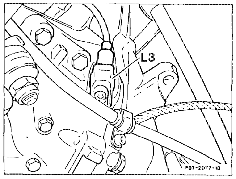
Engine speed sensor (L3) It detects the engine speed at the starter ring gear (144 pulses/revolution) and passes it to the control unit in the form of an alternating voltage.
wii RA 07.1.1032-0010/81
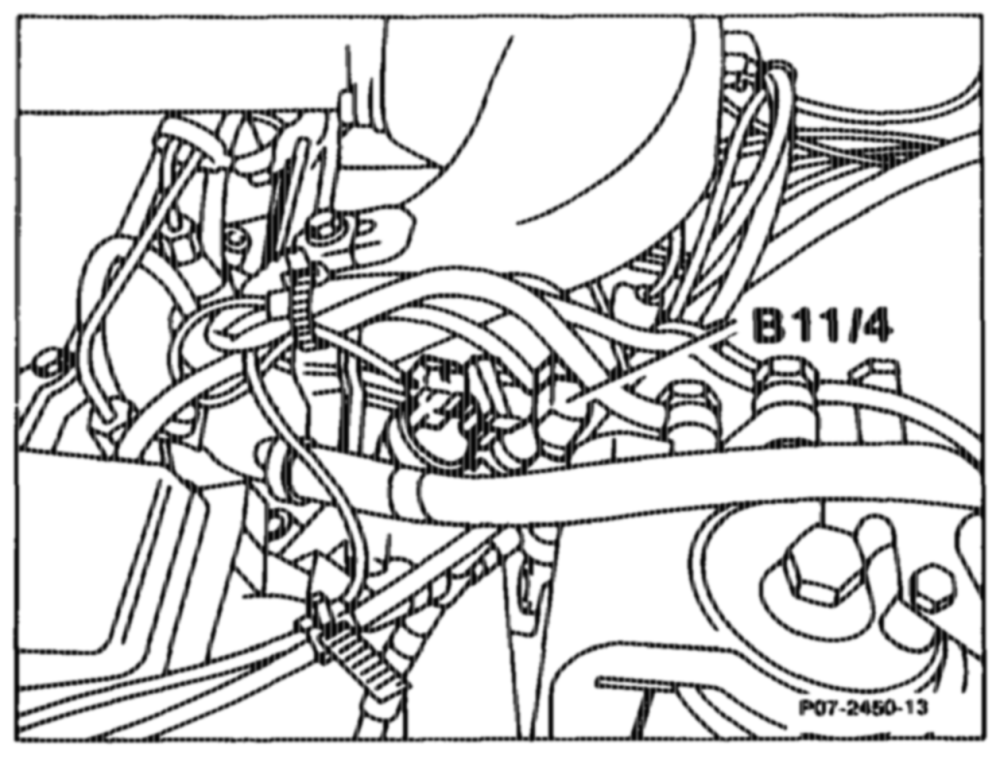
Coolant temperature sensor (EDS) (B11/4) The coolant temperature is detected by the coolant temperature sensor (EDS) (B11/4). The sensor is actuated by the EDS control unit. The resistance of the EDS coolant temperature I) Cb
sensor varies as a function of coolant temperature.
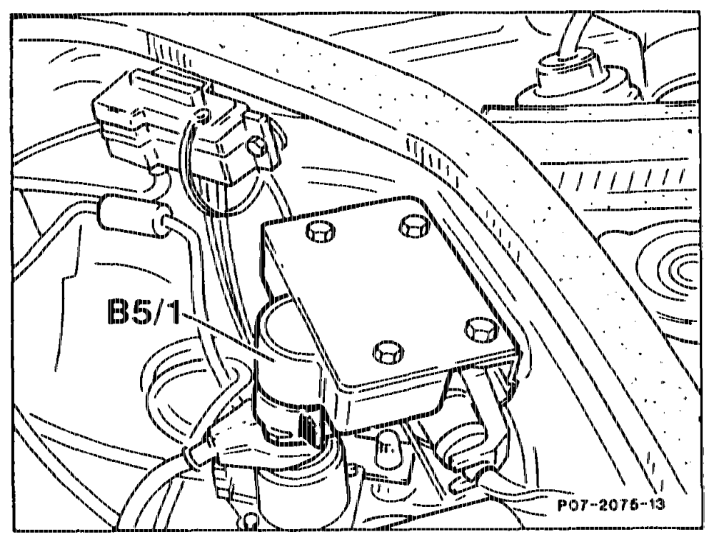
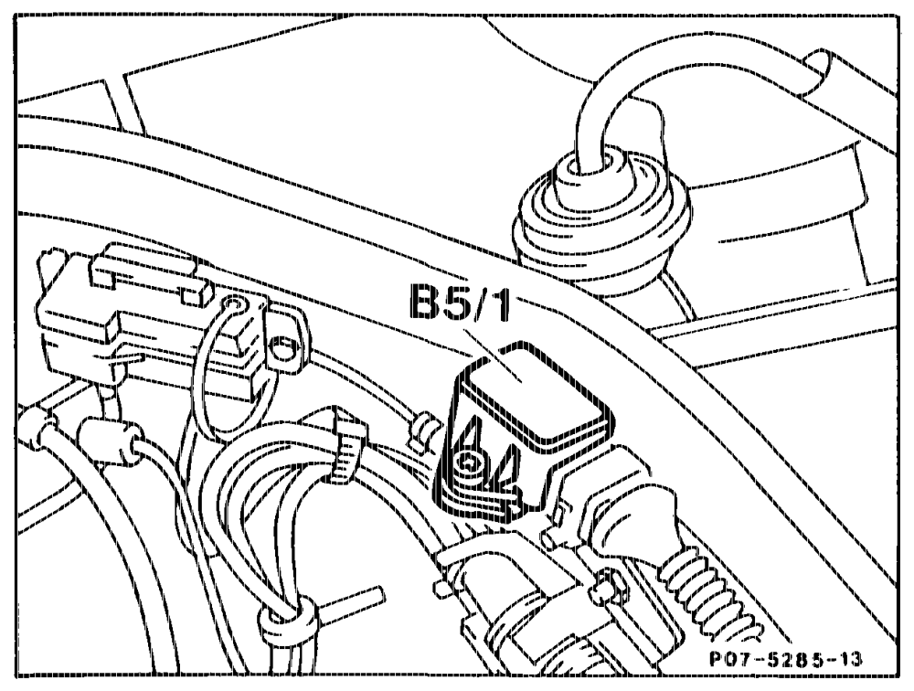
Bosch pressure sensor (B5/1) The pressure sensor detects the existing pressure (P2) and converts it into a voltage which is used as an input signal by the EDS control unit.
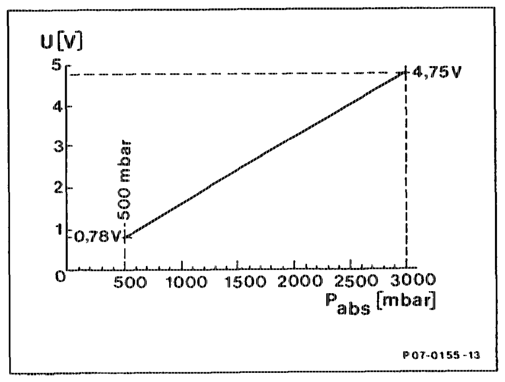
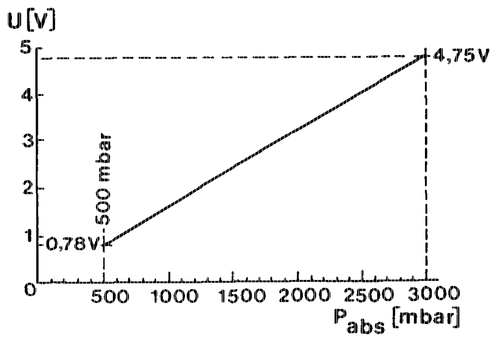
Engine 602.96 up to Model Year 1992 Fitted on right behind firewall in direction of travel
Bosch pressure sensor Absolute pressure characteristic curve (Pabs in mbar) at 5 V voltage
wtrivim = RA 07.1.1032~-0010/82
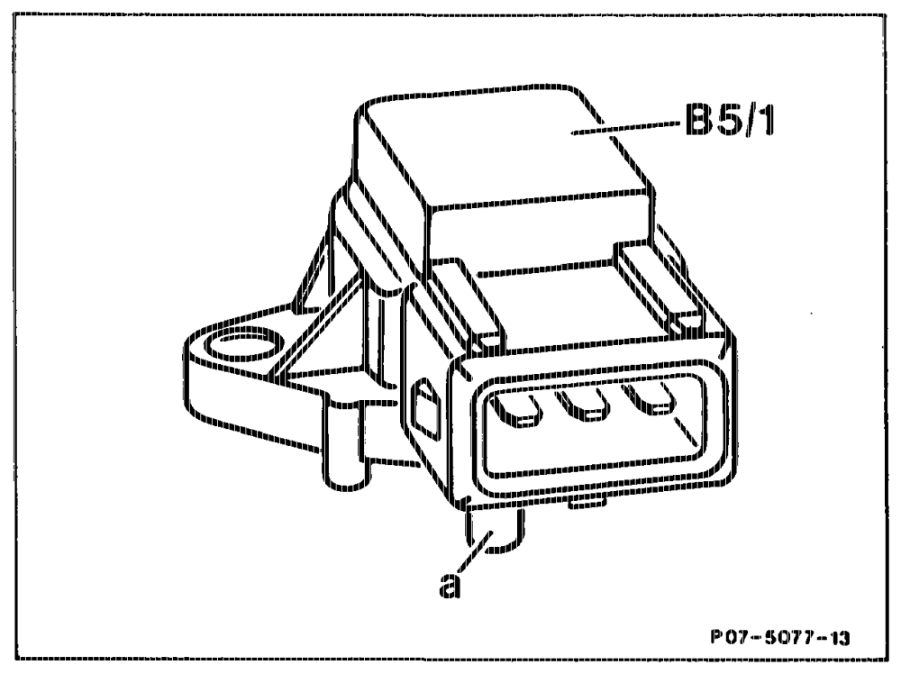
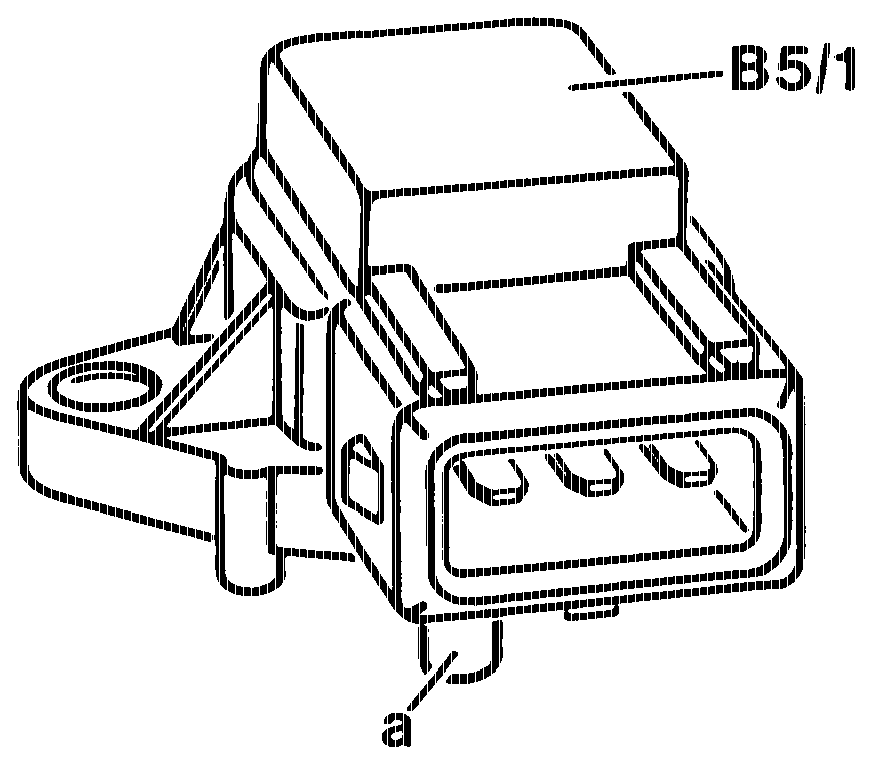
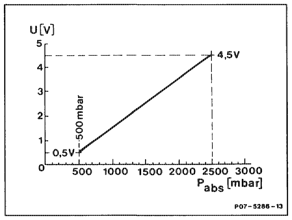
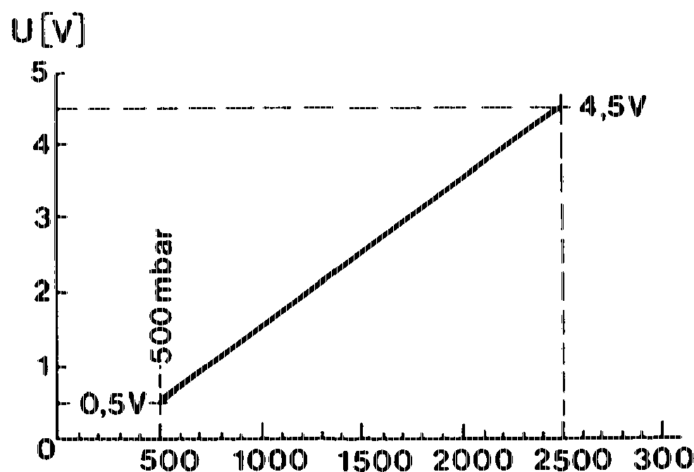
Nippon Denso pressure sensor (5/1 Engines 602.96, 603.971 as of Model Year 1992 The function is the same as for the Bosch pressure sensor.
Nippon Denso pressure sensor Absolute pressure characteristic curve (Pabs in mbar) at 5 volts voltage
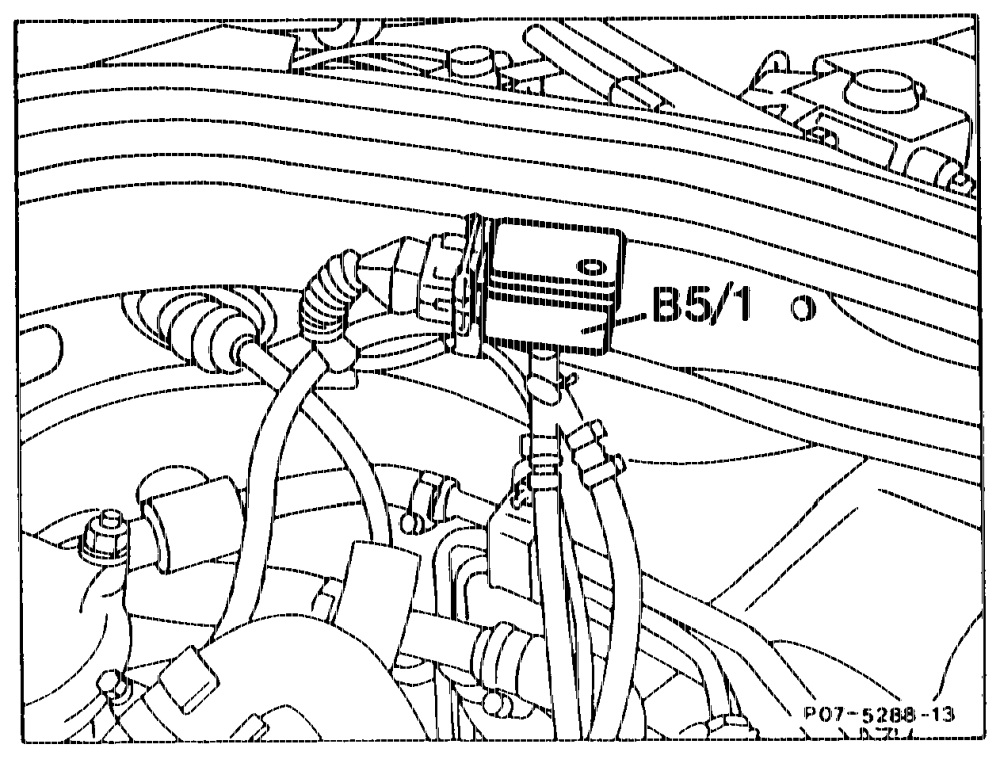
Model 124 On right behind firewall in direction of travel
Model 201,140 ee On left in front of firewall in direction of travel
wim RA 07.1,.1032-0010/83
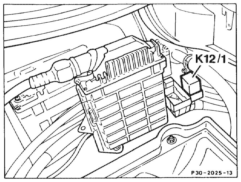
‘Tempomat crulse control, Model Year 1990 In order not to influence the control of the Tempomat cruise control in the part load range, the charge pressure cutoff is rendered inoperative by the Tempomat cruise control/charge pressure cutoff relay (12/1) during use of the cruise control.
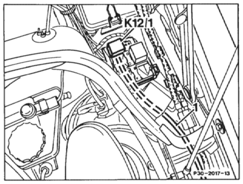
K12/1 Ternpomat cruise control/charge pressure Cutoff relay
Model 201 K12/1 Tempomat cruise control/charge pressure cutoff relay
Note For wiring diagrams see Wiring Diagrams Volume 4 for Model 124 and Volume § for Model 201 Group 30.
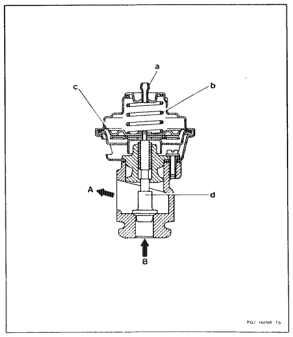
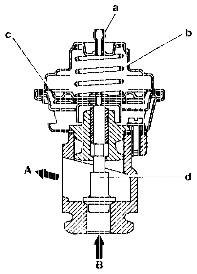
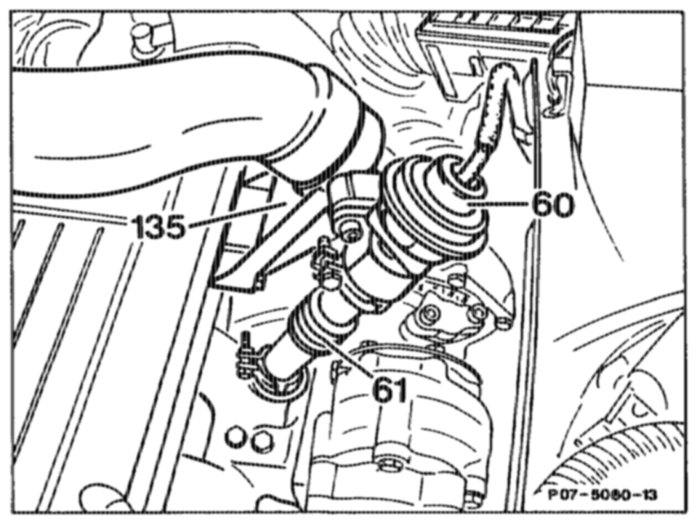
ARF valve The ARF valve is bolted to the mixing pipe on the side of the cylinder head. It is connected to the exhaust manifold by means of a corrugated pipe. The ARF valve is operated by means of a controlled vacuum from the vacuum transducer (Y31/1).
Version up to July 1991
A Exhaust gas to charge air distribution pipe B Exhaust gas from exhaust manifold a Vacuum connection b = Spring c Diaphragm d Valve
awume RA 07,1.1032-0010/84
Notes
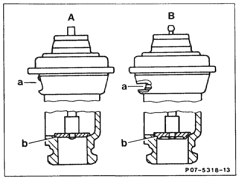
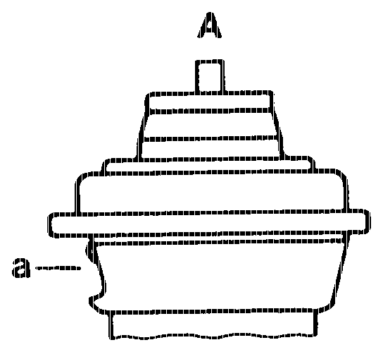
ARF valve of 06/91 For noise reasons, the ARF valve is provided with a smaller air passage (a) and a shaped valve seat (b). The connection fitting for the vacuum connection is designed in a tulip shape.
A. Version up to 06/91 B. Version as of 06/91 a Air passage b= – Valve seat
60 ARF valve 61 Corrugated pipe 135 Mixing pipe
Engine 602.961/962, 603.960/963/971 Cast valve (was steel). Reason: cost and weight reduction.
ote = RA 07.1.1044-0010/85
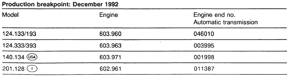
Production breakpoint: January 1993 Model Engine Engine end no. Automatic transmission
124.128/188 602.962 017093
201.128 602.961 011441
Engine 603.960/962/97 1 EGR valve vent restrictor modified.
Production breakpoint as of June 1993 Model Engine Engine end no. Automatic transmission
124.133/193 603.960 048091
124.333/393 603.963 004100
140.134 603.971 004832
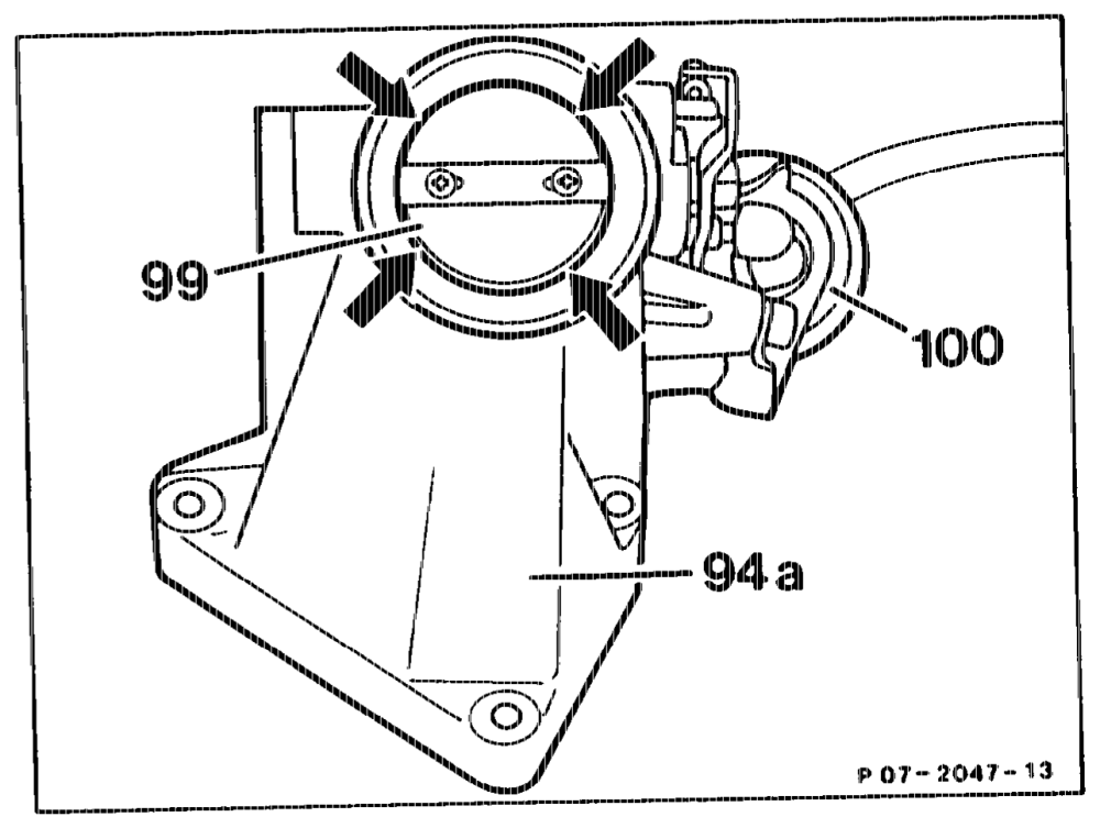
Mixture housing (94a) with vacuum control flap (99) and vacuum unit (100), Engine 602.96 @s4) as of Model Year 1990 Cat) @K) as of Model Year 1991 Basic Version Code 62/0 as of 06/91 CA) Gn) as of Model Year 1992 In order to increase the vacuum in the charge air distribution pipe, a pneumatically operated vacuum control flap is fitted to the mixing housing. The vacuum control flap closes the fresh air port during engine operation with ARF. A minimum opening (arrows) between the vacuum control flap and the mixing housing is retained. As of Model Year 1992 the vacuum unit (100) is actuated by the charge pressure controlvacuum control flap via the vacuum control flap electrical switchover valve (see function diagram).
wii = RA 07.1.1044~-0010/86
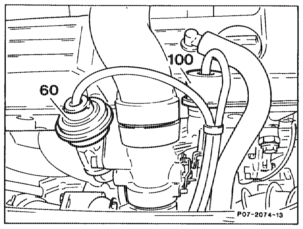
60 ARF valve 100 Vacuum unit
V. Engine overload protection
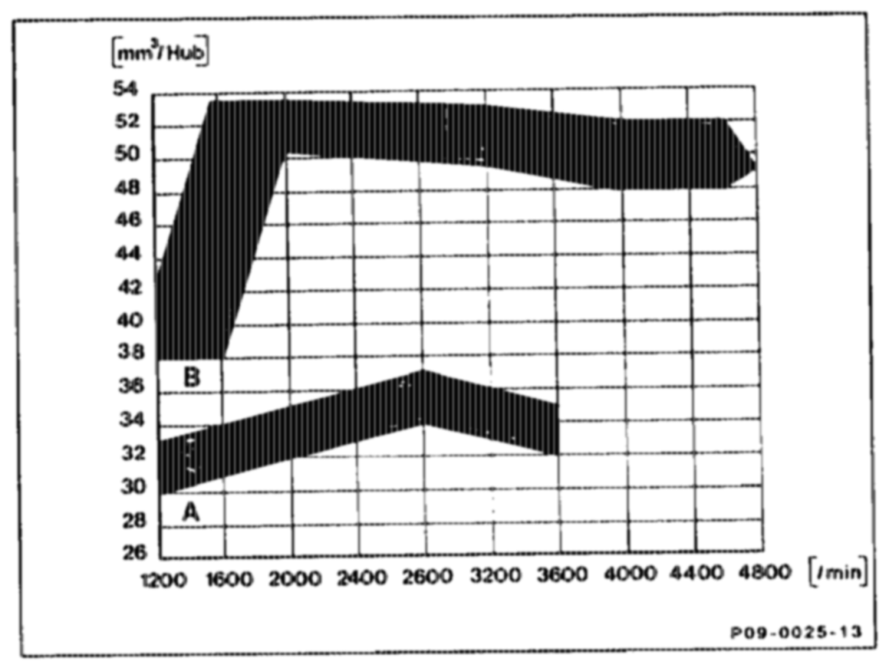
Engines with boost pressure control (P2 control) do not as a general rule have an engine overload protection.
A pressure switch is fitted in the charge air pipe for overload protection of mechanical parts of the engine. If the charge pressure rises above 1.1 + 0.15 bar gauge pressure, air is admitted to the ALDA unit through the switchover valve and the quantity of fuel is limited to that of a naturally aspirated engine.
A Full load quantity without charge pressure (P = 1050 mbar) B Full load quantity with charge pressure
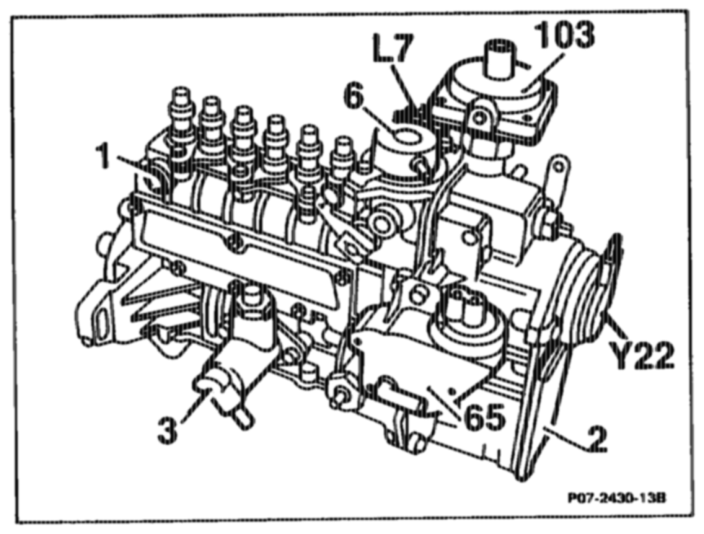
Location of components
1 Injection pump
2 Governor
3 Fuel pump
6 Stop unit 103 ALDA unit Y¥22 Actuator
«wine = RA 07.1.1044-0010/87
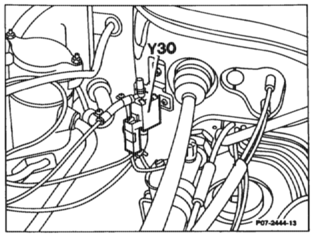
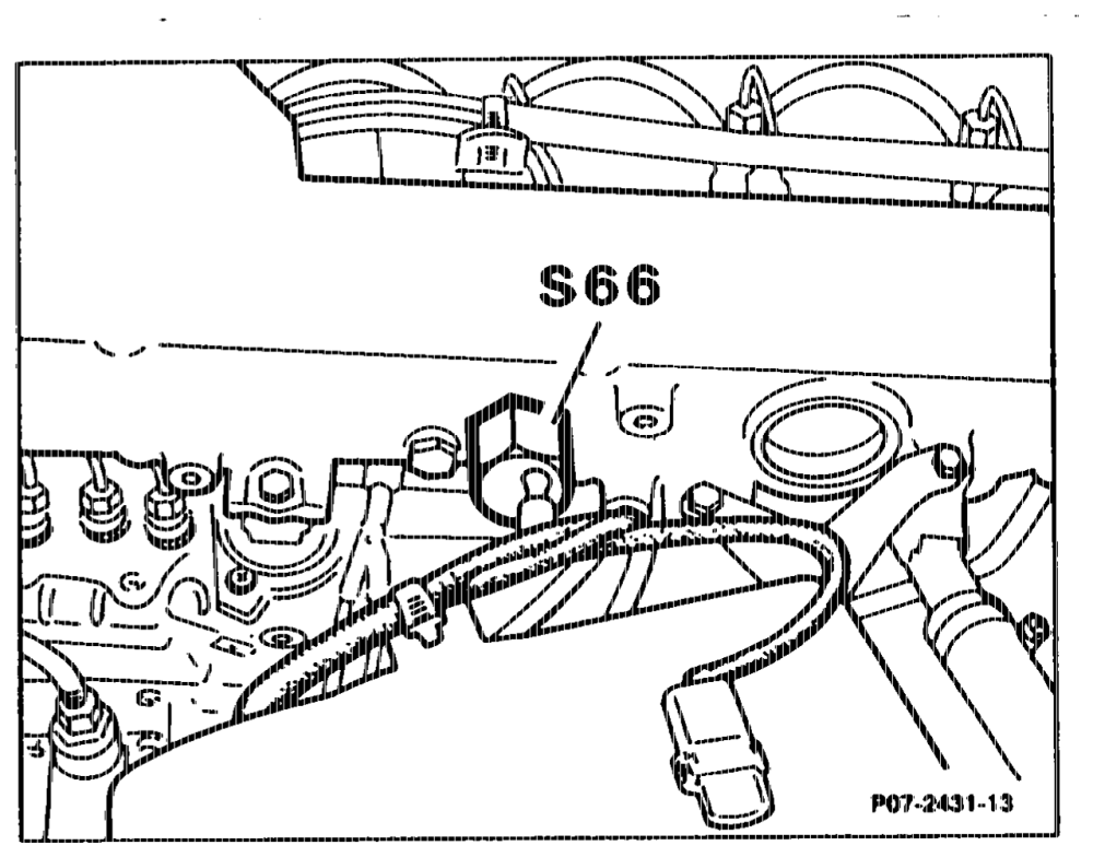
Y30 Switchover valve, engine overload protection
S66 Switch, engine overload protection
Engine 602.962, 603.960/963 Discontinuation of engine overload protection.
Production breakpoint: as of January 1993
Model Engine Engine end no. Engine end no. Manual transmission Automatic transmission
124.128/188 602.962 027382
124.333/393 603.963 004004
Production breakpoint: as of February 1993 Model Engine Engine end no. Automatic transmission
124.128/188 602.962 017181
124.133/193 603.960 046668
onthe = RA 07.1.1044-0010/88
W. Handling electronic control units after accident repair
It is necessary to change electronic control units after an accident, if at least one of the following conditions is met:
1. The housing is recognizably deformed or damaged.
2. The supporting surface or console is deformed; the outside of the unit exhibits no damage.
3. The plug connector is damaged or corroded by moisture.
4. The functional check or the self-test of the equipment indicates faults. When electrical components, e.g. ELR control unit, have been removed for repair work and then used again, these are to be checked in accordance with the existing documents after assembly.
amin = RA 07.1.1044-0010/89