Checking timing of camshafts
WIS 05-2150
Preceding work: Operation no. of operation texts and work units or standard texts Cylinder head covers removed (01-0500). and flat rates 05-6010, 6020
Camshaft code numbers ……. sete eee w ane check (step 1). .
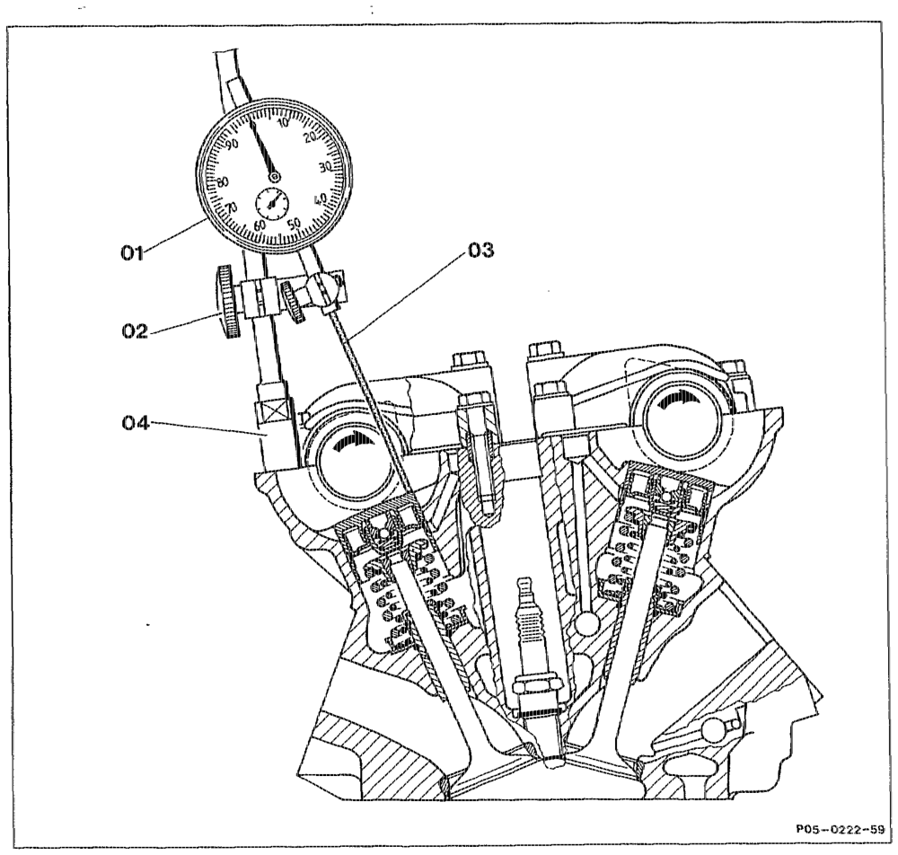
Checking timing of inlet carnshafts Position inlet camshaft of cylinder No. 1 or No. 6 so that only the base circles are resting against the bucket tappets (step 2).
pitty RA 05.1923 21E0/1
Dial gauge holder (02) install with threaded sleeve (04) at cylinder 1 or 6, special tool 363 589 02 21 00 (step 3). Dial gauge (01) install in dial gauge holder (02) with tracer pin (03) on left side of camshafts to be checked (step 4). Preload of 3 mm and angular position of 90° of tracer pin to bucket tappet set (step 5). Crankshaft rotate with wrench socket in direction of rotation of engine, special tool 001 589 65 09 00.
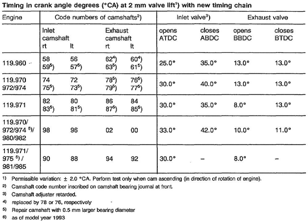
At 2 mm valve lift, the reading on vibration damper must agree with the reading in table „Inlet valve opens”.
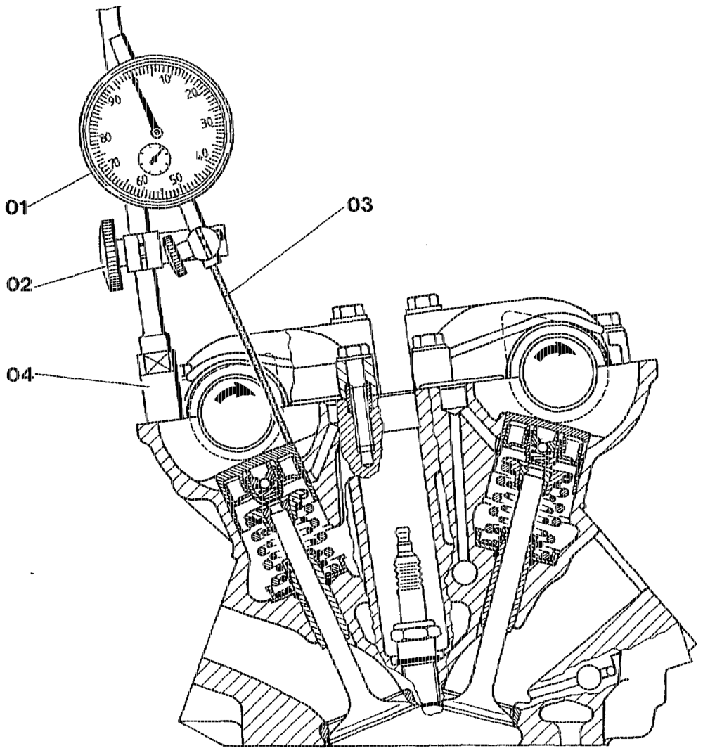
Testing timing of exhaust camshafts Position exhaust camshaft of cylinder No. 1 or No. 6 so that only the base circles are resting against the bucket tappets (Step 7). Dial gauge holder (02) 363 589 02 21 00 with threaded sleeve (04) 2… 0… ee eee eee install at cylinder No. 1 or No. 6 (step 8). Dial gauge (01) with tracer pin (03) install at cylinderNo. 1 on left side at cylinder No. 6 on right side of carnshaft to be tested. Preload of 3 mm and angular position of 90° of tracer pin (03) to bucket tappet set (step 9). Crankshaft crank with wrench socket 001 589 65 09 00 in direction of rotation of engine. At 2 mm valve lift, the reacing on vibration damper must agree with the reading in table „Exhaust valve opens”
opin RA 05.1323-2150/2
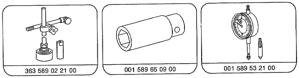
Special tools
athe RA 05.1323-2150/3
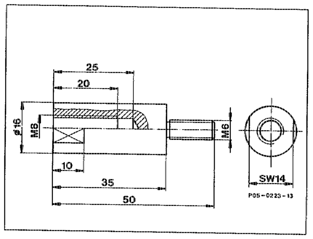
Shop-made tool Threaded sleeve (reduction M8 to Mé) for attaching dial gauge holder 363 589 02 21 00 to cylinder head cover sealing surface.
Note lf performing installation work, it is sufficient to check the basic setting of the camshafts (see 05-2230).
The timing is measured with the hydraulic bucket tappets.
Check „inlet valve opens” at No. 1 and No. 6 cylinder with 2 rm valve lift and camshaft adjuster retarded. Check „exhaust valve closes” at No. 1 and No. 6 cylinder at 2 mm valve residual lift.
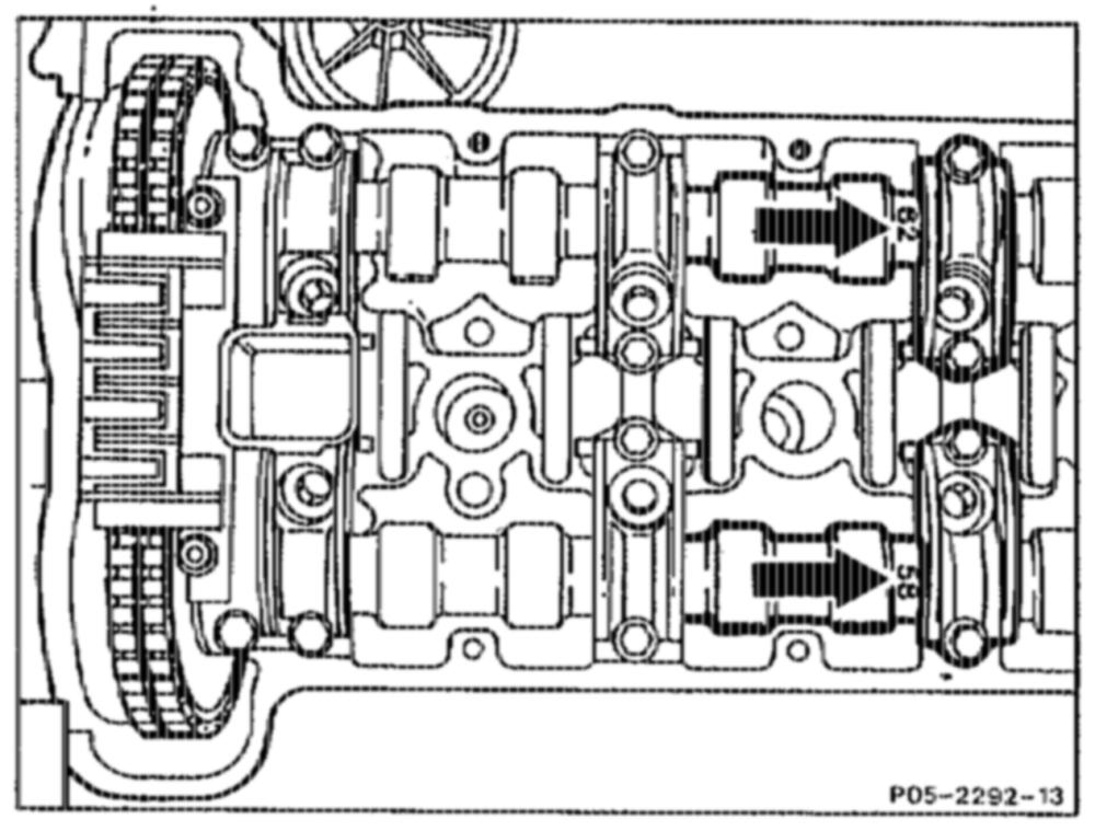
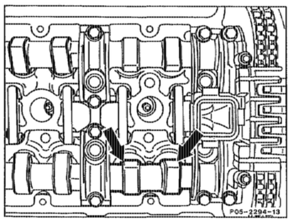
1. Check camshaft code numbers. The camshaft code numbers are inscribed on the 3rd camshaft bearing journal (fitted bearing) (arrows) and stamped on the camshaft flange from behind with coloured ink.
othe §=RA 05.1323-2150/4
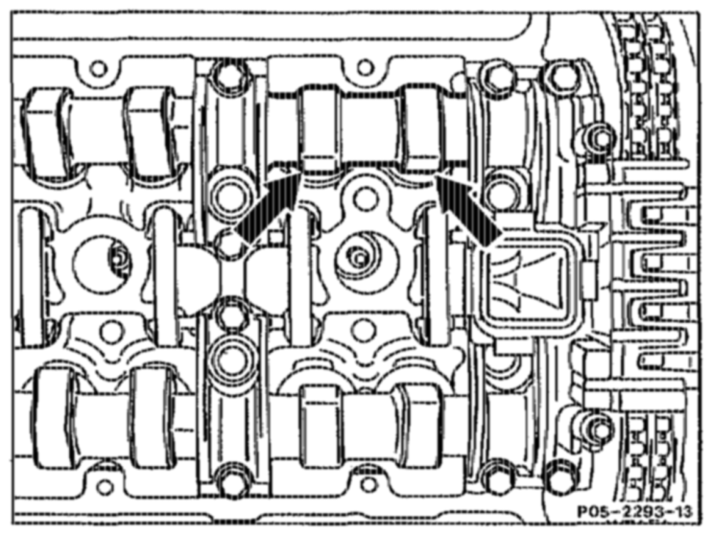
2 Rotate crankshaft in direction of rotation of engine until the lobes of the inlet cams to be tested are facing up (arrows) and only the base circles are resting against the bucket tappets.
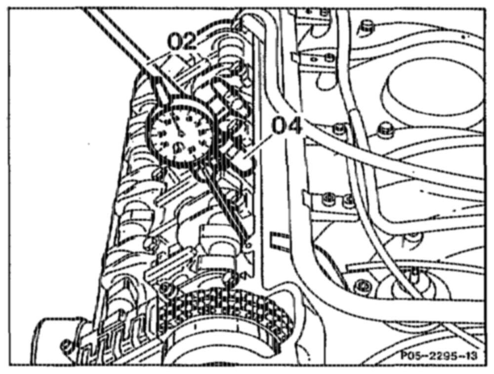
3 Install dial gauge, special tool (02) 363 589 02 21 00 with threaded sleeve (04) at sealing surface of cylinder head cover at the camshaft to be tested.
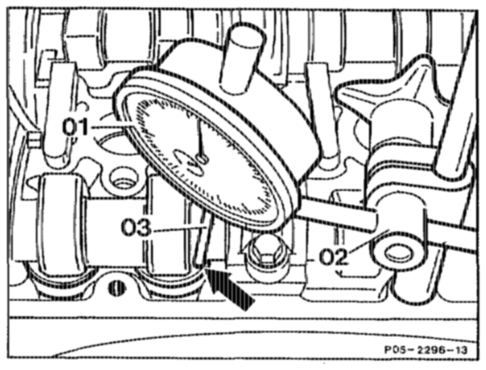
4 Clamp dial gauge (01) with tracer pin (03) (80 mm) in the dial gauge holder (02) so thatthe tracer pin (03) is resting vertically on the bucket tappet (arrow) with a preload of 3 mm (small pointer of dial gauge) inter of cial gauge).
Note Check freedom of movement of tracer pin (03).
§ Turn scale of dial gauge until large pointer of gauge (01) is at „0”.
6 Rotate crankshaft in direction of rotation of engine with wrench socket, special tool 001 589 65 09 00 until the dial gauge indicates a valve lift of 2 mm. In this position, the reading obtained at the vibration darnper must agree with the reading „inlet valve opens ATDC”.
othe RA 05.1323-2150/5
Testing timing of exhaust camshafts
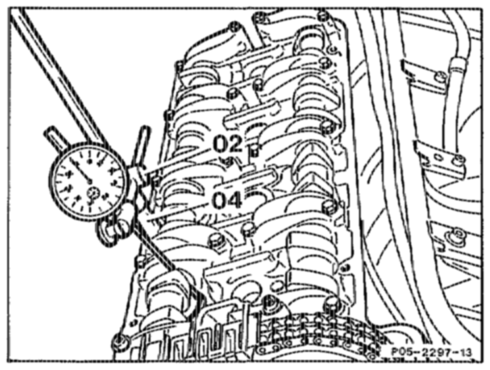
7 Rotate crankshaft in direction of rotation of engine until the lobes of the inlet cams to be tested are facing up (arrows) and only the base circles are resting against the bucket tappets.
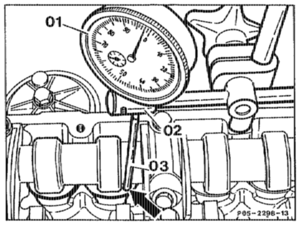
8 Install dial gauge, special tool (02) 363 589 02 21 00 with threaded sleeve (04) at sealing surface of cylinder head cover at the camshaft to be tested.
9 Clamp dial gauge (01) with tracer pin (03) (80 mmm) in the dial gauge holder (02) so that the tracer pin (03) is resting vertically on the bucket tappet (arrow) with a preload of 3 mm (small pointer of dial gauge).
Note Check freedom of movement of tracer pin (03). Install tracer pin (03) at No. 6 cylinder on right of camshaft.
attiy RA 05.1323-2150/6 gauge (01) is at ”0”.
41 Use wrench bit, special tool 001 589 65 09 00, to rotate crankshaft in direction of rotation of engine until dial gauge indicates a valve lift of 2 mm. In this position, the reading obtained at the vibration damper must agree with the reading „exhaust valve closes BTDO”. at)
whe RA 05.1323–2150/7