Removing and installing front engine mounts
WIS 22-2110
Preceding work: Operation no. of operation texts and work units or standard texts Exhaust system removed (49-0045), (49-0170) and flat rates 22-1260-1700
A. Model 124
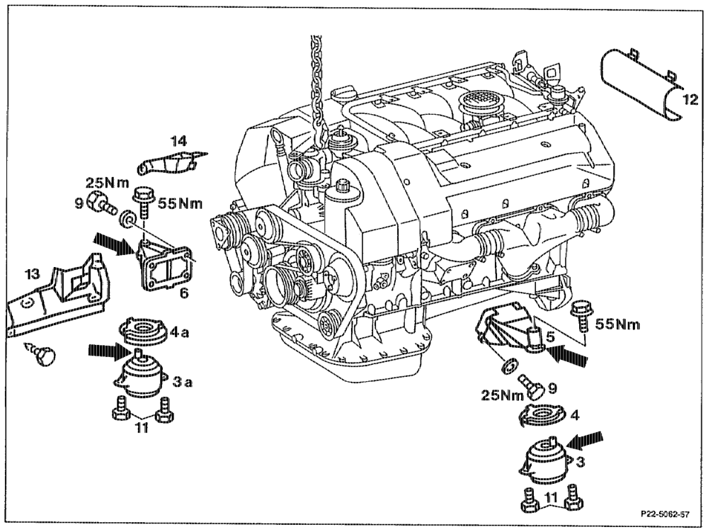
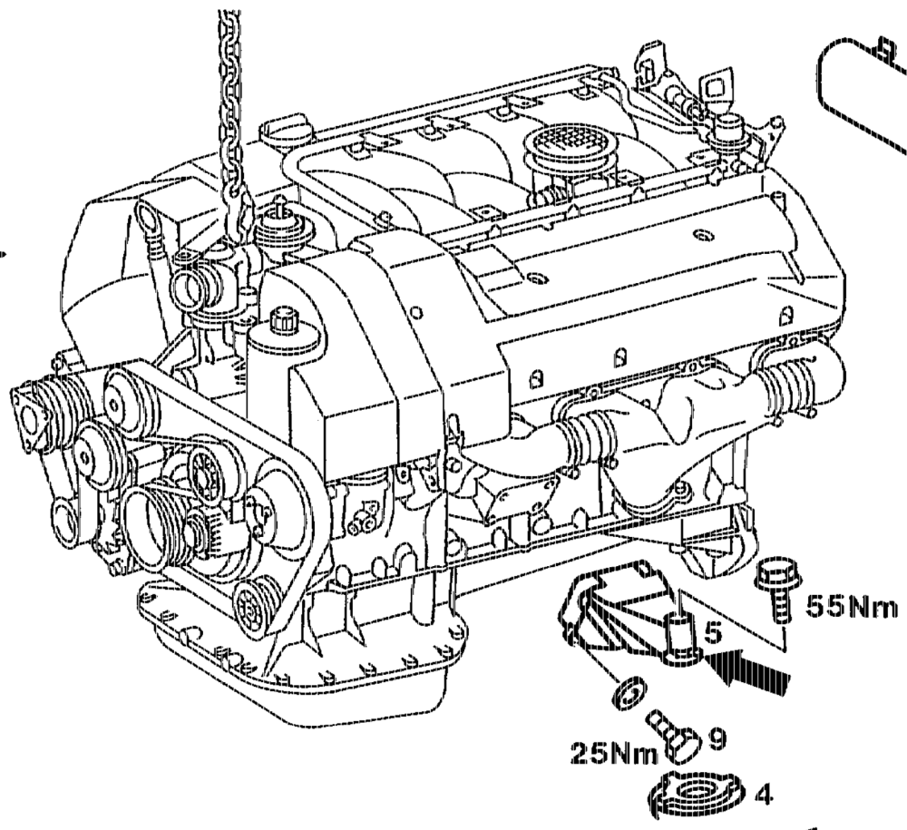
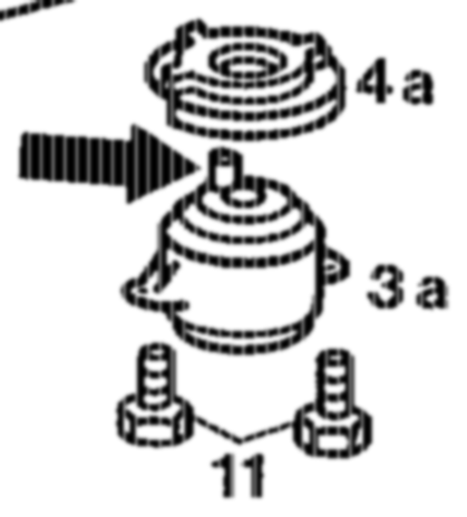
Ground cable at battery… 0.0.2… ce ee eee disconnect, connect. Fan shroud at radiator …….. see eee ee remove, place over fan, install. Cover (12) of engine wiring harness at component partition panel …………..206 detach, attach. Engine mount bolts (11) at bottom unscrew, screw on (25 Nm). Engine at front lifting eye ….. eet wee ene raise. Right engine mount (3): shields (13) and (14)… remove, install. Bolts (9) of engine carriers (5) and (6) …….. unscrew, screw on (M8: 25 Nm; M10: 40 Nm). Engine carriers (5) and (6), engine mounts (3) and (3a) together with shields (4) and (da) ….. remove, install.
aie RA 22.1323-2110/1
Engine mounts (3) and (3a) at engine unbolt, bolt on (65 Nm). carriers (5) and (6) 2… ce ee ee ee eee
Installation note The anti-twist locks (arrows) in the engine mounts (3) and (8a) rnust engage in the openings in the shields (4) and (4a) and in the retaining slots in the engine carriers (5) and (6).
Model 129
5.
Operation no. of operation texts and work units or standard texts Preceding work: and flat rates Intake air scoops removed (09-0015). 221 260-1700
Ground cable at battery 0… 2… 6. eee eee disconnect, connect. Fan shroud ring ……-. wee ee eee remove, place over fan, attach.
installation note Ensure the 4 engaging points are correctly located.
opto yin
RA 22.1323-2110/2
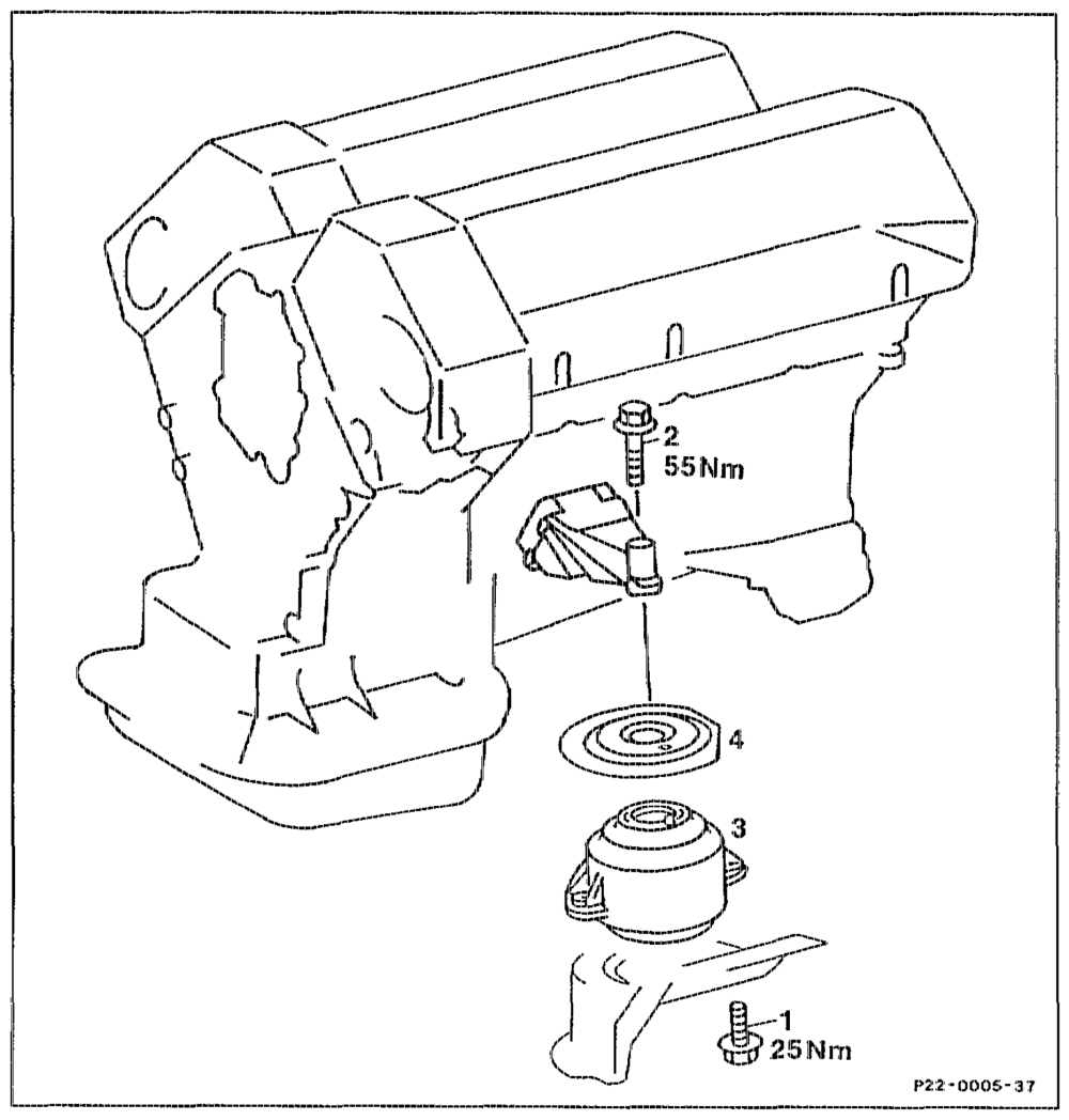
Bottom engine compartment panel ……….. remove, install (Maintenance Manual 6190). Bolts (1) 2… ee ee ee ee ee eee unscrew, screw on (25 Nm). Engine at front lifting eye ……………… raise, lower.
AN When raising, pay attention to accelerator control at rear and coolant hoses. Bolts (2) 2… eee eee vee eee eee unscrew, tighten (65 Nm). Engine mount (3) with shield (4) ………..6. remove, install (step 9).
Note If vehicle fitted with AC, remove drag link, install (46-5500).
Installation note The anti-twist lock iin the engine mount (3) must engage in the opening in the shield (4) and in ; the retaining slot in the engine carrier. Shields (4) ………..00. steer e eww n ees on left and right are identical.

Tightening torques in Nm
wth RA 22.1323-2110/3
Cc. Model 140
Operation no. of operation texts and work units or standard texts Preceding work: and flat rates Intake air scoops rernoved (09-0015). 22–1260-1700 Bottom engine compartment panel removed ({Mainitenance Manual 6190).
Ground cable at battery disconnect, connect. Fan shroud ring 2.0.0.2… eee eee eee eee remove, place over fan, attach.
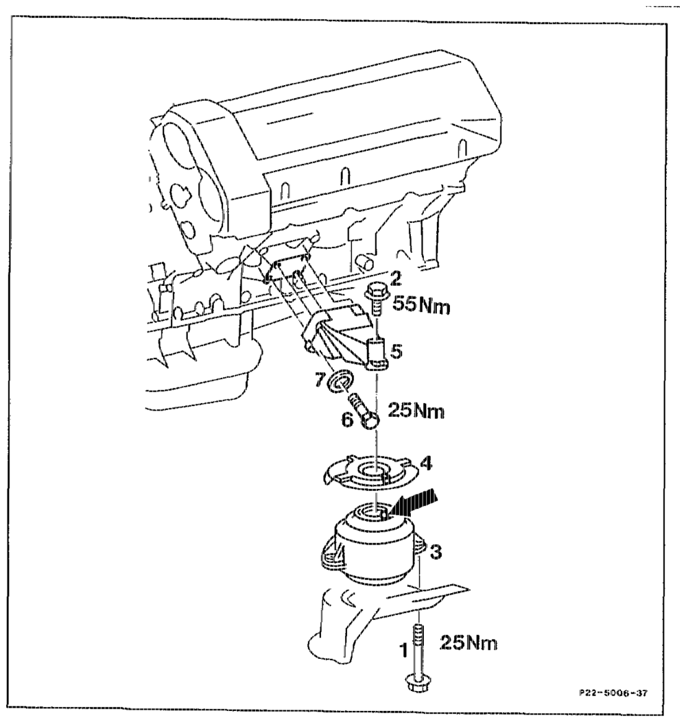
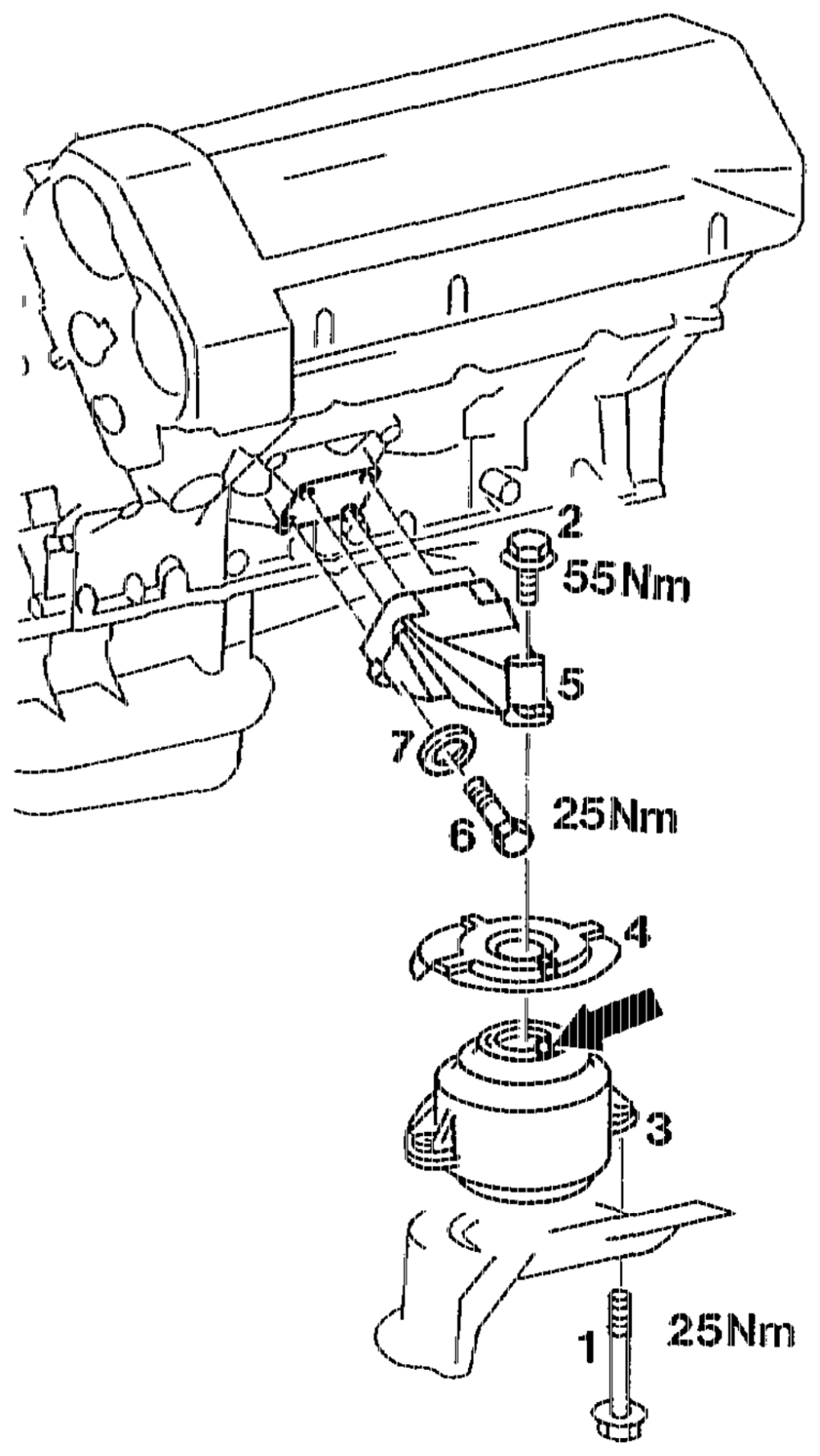
Installation note Ensure the 4 engaging points are correctly located. Bolts (1)… eee eee scene ee eee unscrew, screw on (25 Nm). Engine at front lifting eye …………02.00. raise about 5 mm, lower, Bolts (6) of engine carrier unscrew, screw on (25 Nm).
atte RA 22.1323-2110/4
Engine at front lifting eye cease raise about 40 mm, lower.
An When raising, pay attention to accelerator control at rear and to coolant hoses. Engine mount (3) with shield (4) ancl engine carrier (5)… 6… eee remove downward, install. Engine mount (3) at engine carrier (5) unbolt, bolt on (55 Nm). Shield (4) at engine mount (3) take off, install.
Installation note The anti-twist lock (arrow) in the engine mount (3) must engage in the opening in the shield (4) and in the retaining slot in the engine carrier.

Tightening torques in Nm
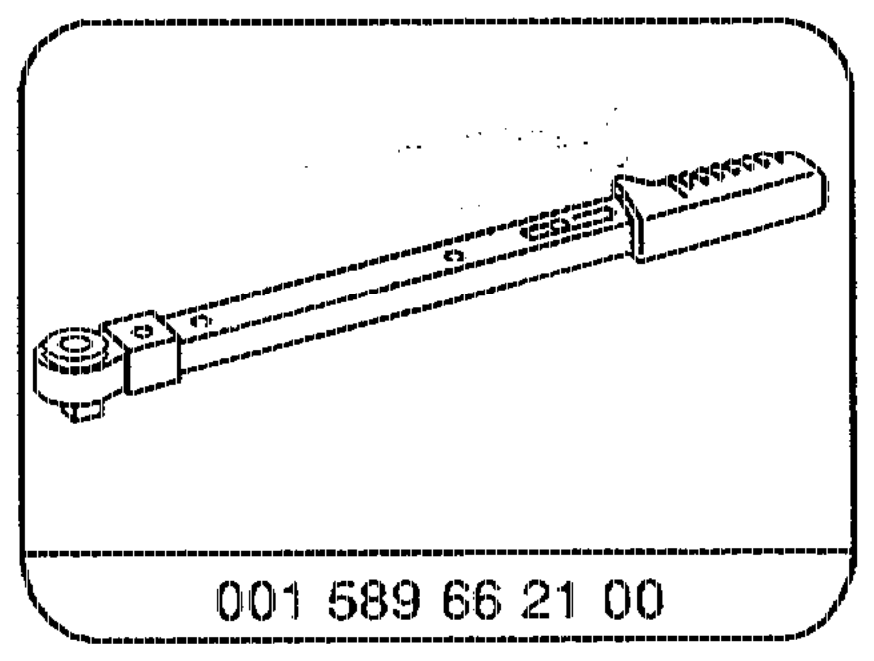
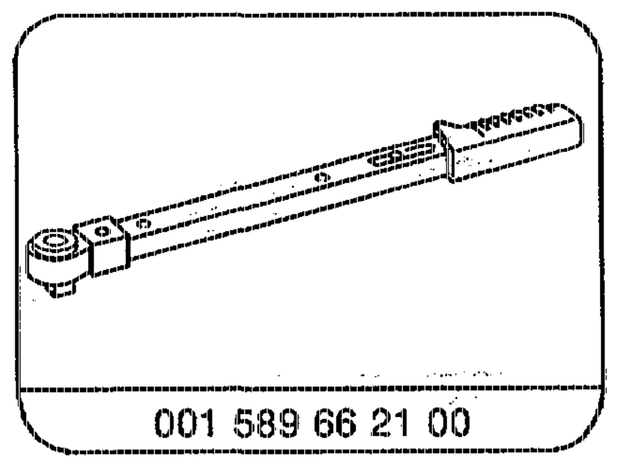
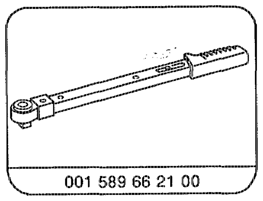
Special tool
nimi §~RA 22.1323-2110/5
D. Model 210
Preceding work: Operation no. of operation texts and work units or standard texts Bottom engine compartment panel removed and flat rates (Maintenance Manual 6190). 22-1260-1700
Fan shroud ………e20eeeeeeeeeesse.. take off, place over fan, fit on.
Installation note Ensure the engaging points are correctly located. Engine mount (14) at bottom 0… eee eee unbolt, bolt on (30 Nm). Engine 2… 2… ee ee ee ee eee seeeee raise about 5 mm at front lifting eye, lower.
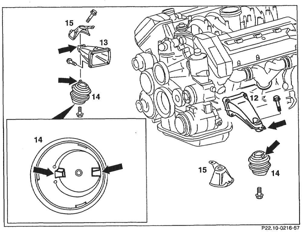
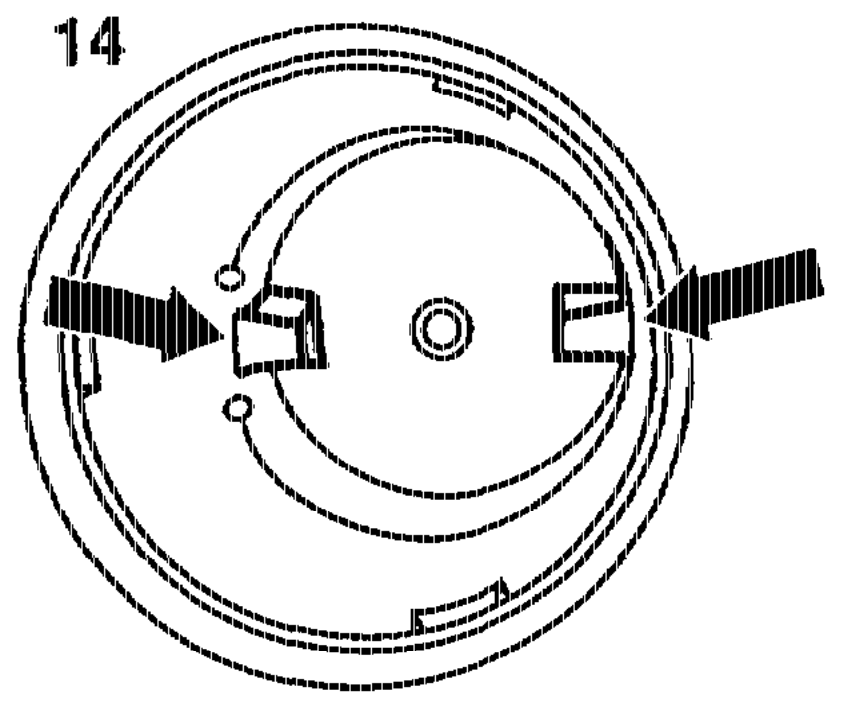
Note The installation position of the engine mounts (14) to the front suspension carrier is fixed by recesses (arrows) in the engine mounts (14) and raised faces in the front suspension carrier. Engine mount on right: engine mount (14) complete with engine carrier (13) remove; unbolt engine mount (14) from engine carrier (13), install.
atimge RA 22.1323-2110/6
Engine mount on left: engine mount (14) at engine carrier (12) atatop 2.0… eee ee eee unbolt, bolt on.
Note The anti-twist lock (arrow) in the engine mounts (14) must be inserted into the opening in the shield (15) and into the retaining slot in the engine carrier (12 or 13) (arrow). The shields (15) are bolted to the engine carriers (12 or 13) with the top bolt.
Tightening torques in Nim Hexagon bolts for engine mount to front suspension carrier 30
Hexagon bolts for engine mount to engine carrier 55
atin RA 22.1323-2110/7