Removing and installing driven plates
WIS 03-4100
Preceding work: Operation no. of operation texts and work units or standard texts Transmission removed (27-6000). and flat rates 03-8201, 8214
A. Engine 119.960/97
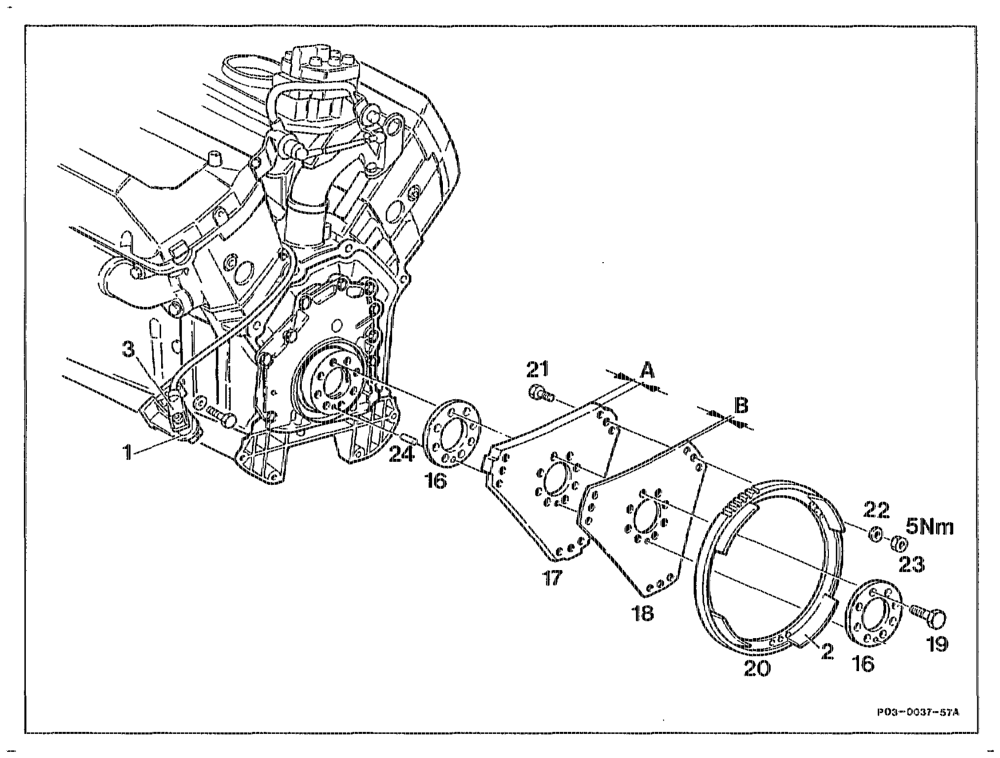
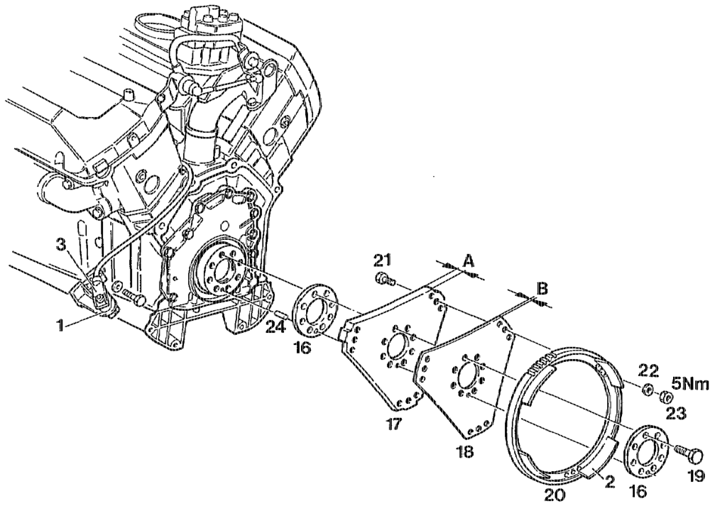
17—_~Driven plate A= 1.5 mm 18 = Driven plate B= 1.0 mm
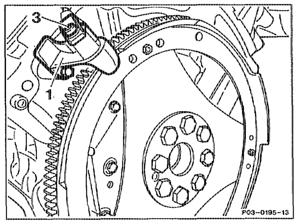
Retaining lock for crankshaft/ring gear …….. — install, remove (03-5000). Position sensor (3) of ignition control unit with bracket (1)… ee eee eee ee eee unbolt, bolt on (step 2). Stretch bolts (19)… ee ee unbolt, replace (steps 3 and 4). Driven plates (17) and (18) 2… eee eee take off, fit on. Installation position and installation order ……. note (steps 5 and 6).
othpe RA 03.1313-4100/1
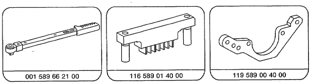

Note Driven plates and ring gear are balanced individually and can be replaced without balancing. The tapped holes in the crankshaft flange are drilled through. If the bolts are removed and the engine is tilted, engine oil flows out of the tapped holes.
oti RA 03.1313-6100/2
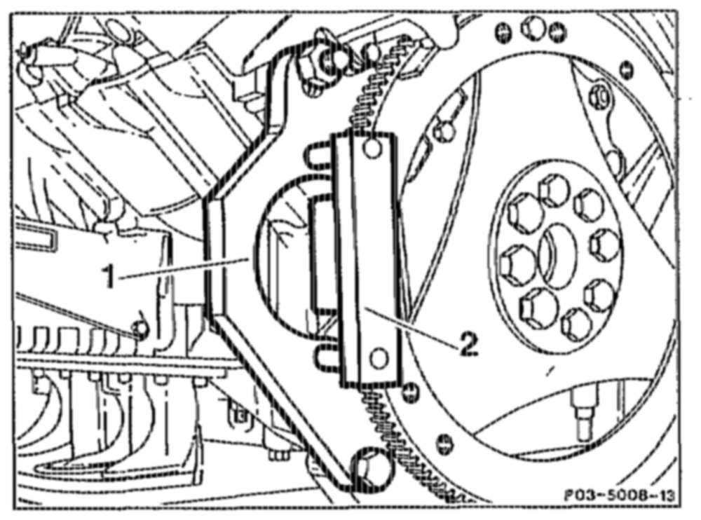
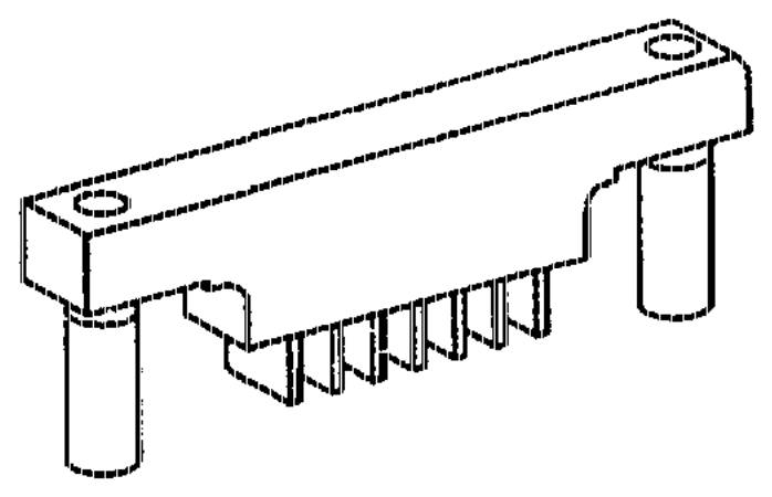
1 Remove retaining lock for crankshaft/ring we is gear, install (03-5000).
2 Unbolt position sensor (3) of ignition control unit together with bracket (1).
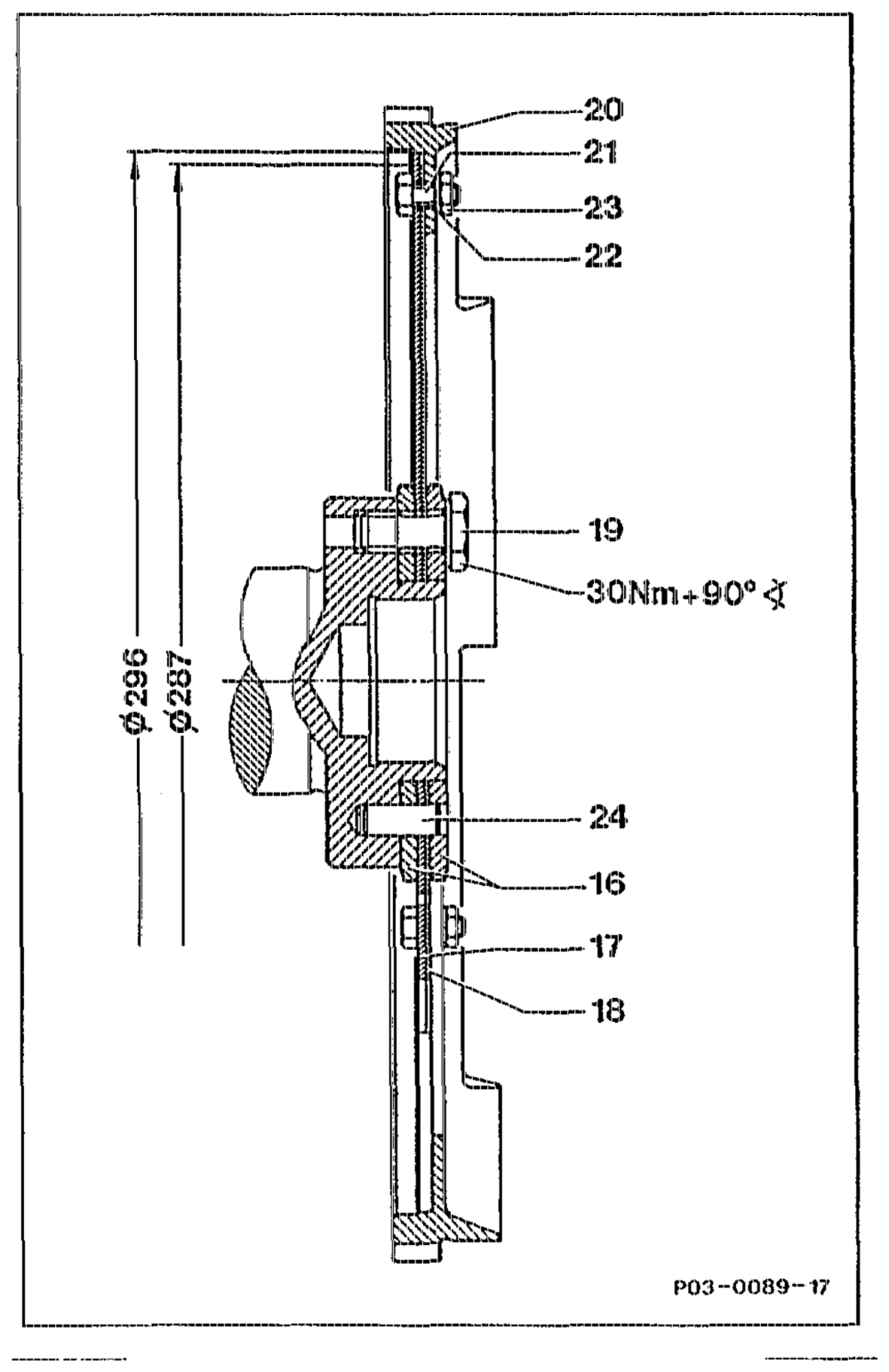
3 Remove bolts (19). Take off driven plates together with ring gear (20).
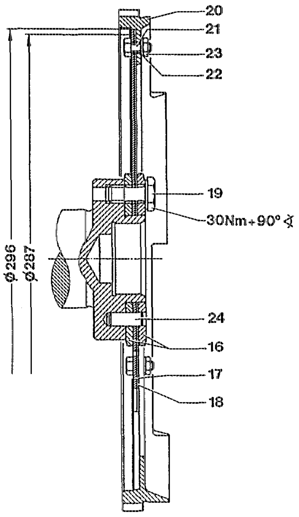
4 Install driven plates at crankshaft flange. Install thicker driven plate (17), thickness 1.5 mm, on inside. Insert stretch bolts (19).
AN Mounting surface of driven plates, of bolts and plate mounts must be free of damage and dirt. Install bolts (19) without sealant otherwise leaks may occur.
wttin RA 03.13913-4100/3
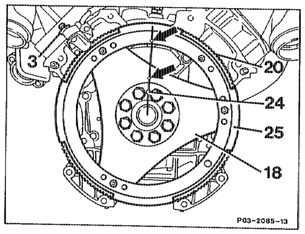
5 Fit ring gear (20) onto driven plates (17 and 18) and tighten nut (23) 5 Nm.
aN The ring gear must be installed so that the 3.6 mm dia. holes (arrows) in the ring gear and in the driven plates have the same angular position, otherwise proper operation of the ignition is not assured.
6 Kurbelwelle gegen Verdrehung fixieren. ‘siehe Ziffer 1).
7 Tighten bolts of driver to initial torque of
30 Nm and tightening angle of 90°.
Note Bolts are microencapsulated; use only once.
8 Screw on position sensor of ignition control unit with bracket.
aim ~=RA 03.1313-4100/4
B. Engine 119.98
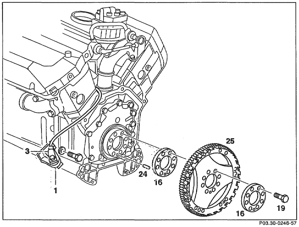
25 Driven plate, starter ring gear and increment gear are a fixed riveted assembly as of start of production of M119.98.
Retaining lock for crankshaftring gear… 2… install, rernove. (03-5000). Position sensor (3) of ignition control unit with bracket (1) 60… eee ee eee ee unbolt, boit on. Stretch bolts (19) ………. see een eee unscrew, replace.
Combined driven plate/starter ring gear (25) …. — take off, fit on.
ZN Mount of driven plate, of bolts and plate mount must be free of darnage and dirt. Install bolts (19) without sealant otherwise leaks may occur. Installation position and installation order ……. note.
A The driven plate (25) and the plate base (16) must be installed so that the dowel pin engages in the @ 8 mm hole.
atiie RA 03.1313-4100/5
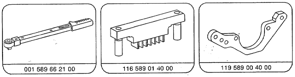
Thread @ M 12% 1.5
Initial torque 30–40
hightening angle 90~100°
Note The threaded holes in the crankshaft flange are drilled through. If the bolts are removed and the engine is inclined, engine oil flows out of the threaded holes.
aime RA 03.1313-4100/6