Removing and installing, adjusting firewall accelerator control shaft
WIS 30-320
A. Model 107
Preceding work: Removing accelerator pedal ………….. .. 30-330 Removing heater box 000000000 83-100
€90-007%-51
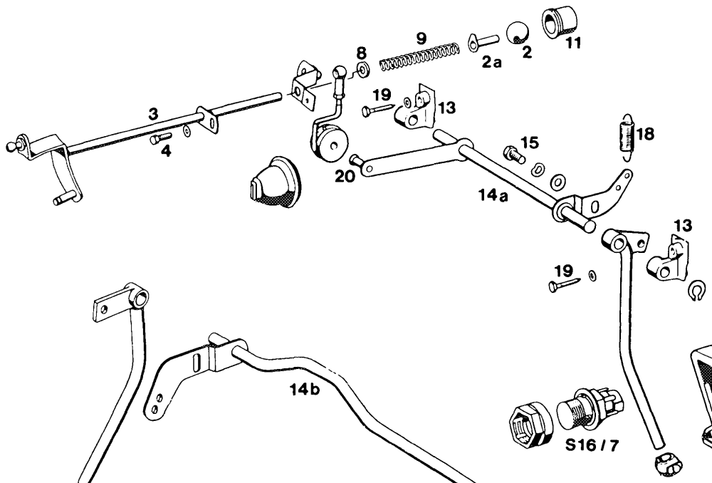
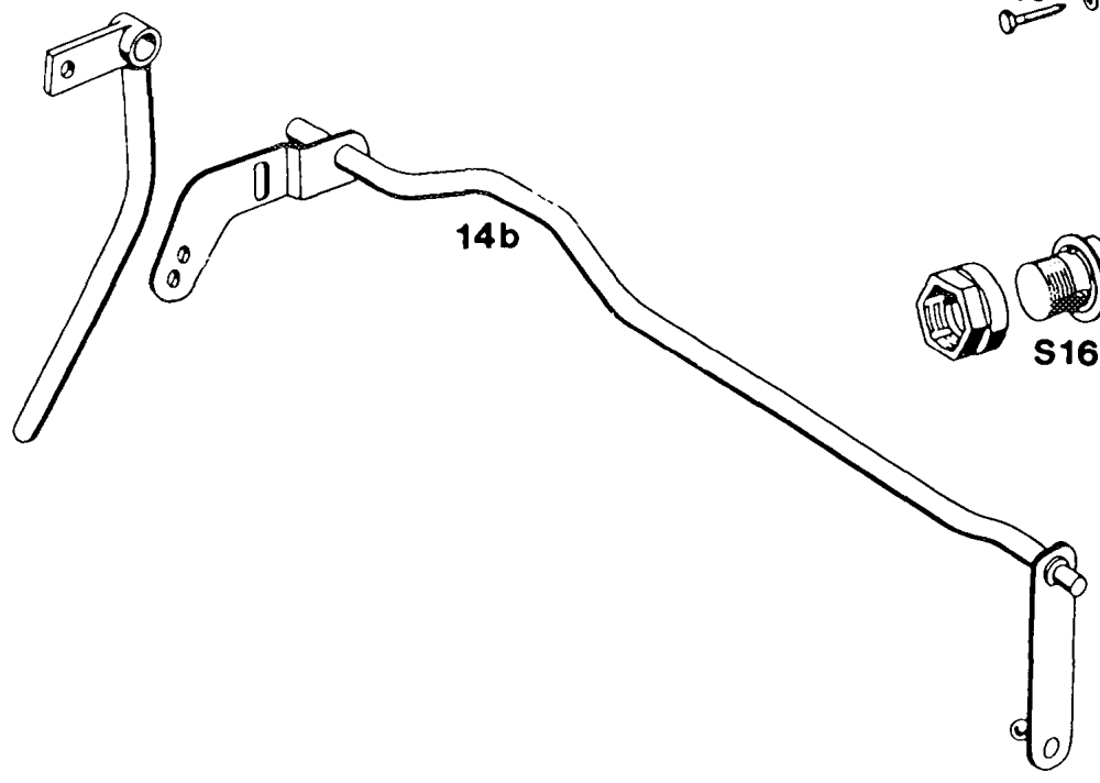
Connecting link with damping ring (20) …….. press off lever of accelerator control shaft (14a) (14b, not used), press on. Return spring (18) «6.2.2… 00.00. e eee eee detach, attach in top hole. Fastening bolts (19) 000000 unscrew, screw on. Plastic bearing (13) 6.0… cee ee eee press out up the way and take off accelerator control shaft with bearing. Bearing points and ball sockets …………. grease with Molykote-Longterm 2.
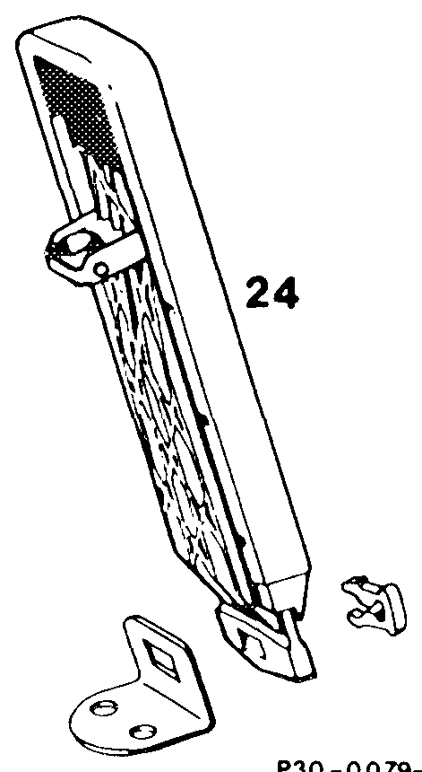
Accelerator pedal (24) depress as far as stop on kickdown switch (S16/7). When doing this, the throttle vaive lever must be resting against full throttle stop. If necessary, correct setting by slackening screw (4). If this setting does not produce full throttle or idle stop, adjust linkage rod (20) of longitudinal control shaft (14a) to length of 105 mm, measured from center of ball socket to center of damping ring. As acheck, slowly allow accelerator pedal to move back into idle position. In this position, the roller in the fulcrum lever must be resting free of tension against end stop. If the setting described above does not produce full throttle or idle stop, slacken hex. bolt (15) in interior of car, press accelerator control linkage up to full throttle stop on throttle valve assembly and retighten hex. bolt.
B. Model 126
Preceding work: Removing accelerator pedal …….
P30 -0077–55
Model 126
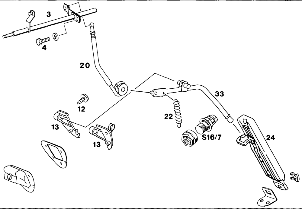
Return spring (22) detach and attach. Connecting link (20) pull off accelerator pedal lever (33), press on. Fastening bolts (12) unscrew, screw in. Bearing (13) with accelerator pedal lever (33) remove.
Installation
Grease bearing points and ball sockets with MolykoteLongterm 2. depress as far as the stop on kickdown switch Accelerator pedal (24) (S16/7). When doing this, the throttle valve lever must be resting against full throttle stop. If necessary, correct setting by slackening the bolt (4). If this setting does not produce full throttle or idle stop, proceed as follows: Adjust connecting link (20) from longitudinal accelerator control shaft (3) to accelerator pedal lever (33) to a length of 220 mm, measured from center of ball socket to center of damping ring.