Checking, adjusting accelerator control
WIS 30-300
A. Vehicles without ASR
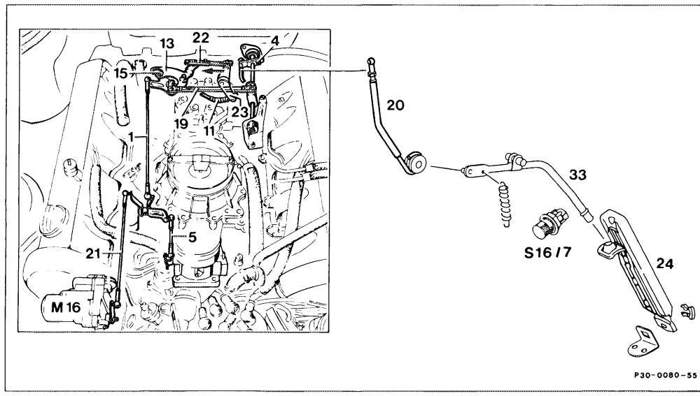
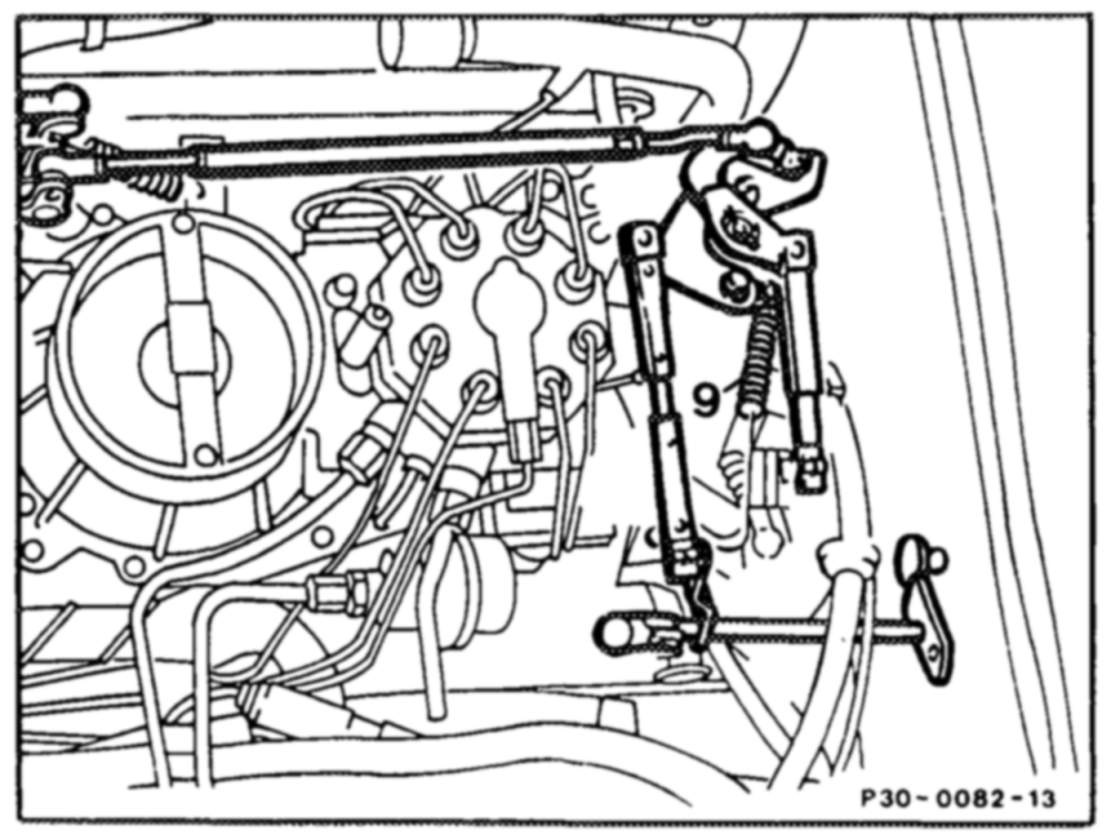
Accelerator control linkage …………….. check that it operates easily and is not bent. Renew parts, if necessary. Connecting link (5) and linkage rod (21) ……. detach at relay lever. Check whether the throttle valve is resting against idle speed stop. Reattach connecting link free of tension. Adjust to 100 mm length, if necessary (measured from ball socket centers). Vehicles with cruise control …………004. check whether cruise control actuator (M16) is resting against idle stop of cruise control. This is done by detaching linkage rod (21) and pressing lever of actuator clockwise against idle stop. When attaching linkage rod (21), ensure that the lever of the actuator is pressed away approx. 1 mm from the idle stop. Adjust linkage rod (21), if necessary (measured from ball socket center).
detach. Connecting link (22) adjust so that the roller (15) in the fulcrum lever Connecting link (1) (13) is resting free of tension against end stop. adjust to 163 mm and attach (measured from Connecting link (19) center of ball socket). check. With engine switched off, depress accelFull throttle stop erator pedal (24) from inside car as far as stop on kickdown switch (S16/7). The throttle valve lever must be resting against full throttle stop when performing this step. Slacken adjusting screw (4), if necessary, adjust accelerator control linkage so that throttle valve lever is resting against full throttle stop. If this adjustment does not result in full throttle or idle stop, adjust linkage rod (20) to specified length (see table). From center of ball socket to center of damping ring. As a check, allow accelerator pedal to slowly move back into idle position. In this position, the roller in the fulcrum lever must be resting free of tension against end stop. Control pressure cable (11) for automatic transmisSION 0.0.0.0… ee ee adjust. To do this, press relay lever (23) in direction of arrow until it is felt to touch idle stop of automatic transmission. Attach connecting link (22) free of tension; adjust, if necessary.
Adjustment data in mm (measured from center of ball socket)
Model 107 126
Length of connecting link (5) from throttle 104 104 valve assembly to relay lever
Length of linkage rod (20) from longitudinal 105 220 accelerator control shaft to accelerator pedal
Length of connecting link (19) from longitudinal 163 163 accelerator control shaft to fulcrum lever
8. Vehicles with ASR
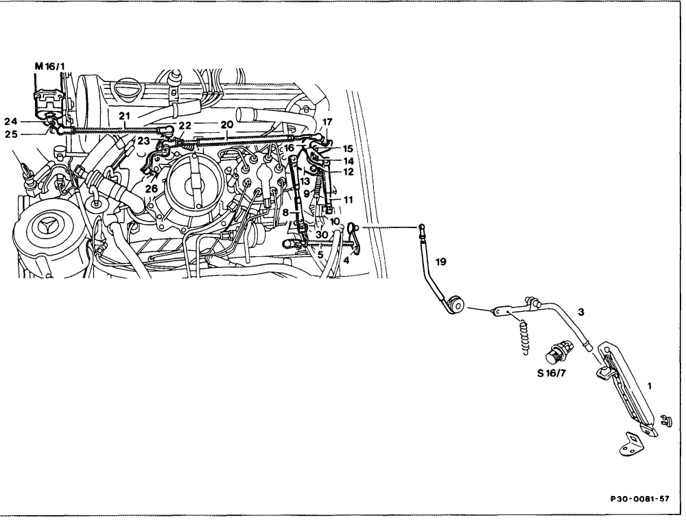
Air filter 2… ee eee remove. Return springs (9, 22) 2… eee ee eee check whether throttle valve relay lever (23) is correctly attached at potentiometer (see note for ill.). Locking element (14, 25) ………….0000. check that correctly fitted. Connecting links (8,11) …………00-005 detach at accelerator control lever (16) and at fulcrum lever (13). Idle travel rod (20)… eee ee eee remove. This is done by pulling off accelerator control lever (16) and throttle valve relay lever (23) e.g. with open-end wrench.
AN On no account bend idle travel rod otherwise pressure point in accelerator pedal or idle travel rod will not move easily.
must be resting against outer cam of fulcrum Accelerator contro [lever (16) …………02, lever (13). Ease of movement 00000 eee of accelerator control lever and fulcrum lever, check.
check length. To do this, fit idle travel rod (20) Idle travel rod (20) onto accelerator control lever (16). In idle position, setting size must be 3–5 mm longer (approx. half ball head) than the distance between throttle valve relay lever and potentiometer accelerator control lever.
LN Adjust length only at the knurled edge. The ball sockets must not be released and repositioned. fit at throttle valve relay lever (23). Idle travel rod (20) Output lever (24) check. To do this, switch on ignition. Output lever must assume idle position. Check whether output lever can be shifted further by hand. If yes, perform test routine for electronic accelerator (30-365). Wee cece eee eee eeee Connecting link (2 adjust length (left/right thread) so that rocker play at throttle valve relay lever (23) in pull direction is eliminated (throttle valve opens immediately when potentiometer operated). Full throttle stop check. To do this, fully deflect potentiometer accelerator control lever (16) and hold in this position. Check at throttle valve assembly whether the throttle valve is resting against full throttle stop (linkage not subjected to excessive pressure). If full throttle stop is not reached, slacken hex. nut on ball head in output lever (24). Operate potentiometer accelerator control lever as far as full throttle stop and fix in position. Pull connecting link (21) into full throttle position and hold in this position. Secure ball head.
check. With one hand, slowly deflect potentiometer accelerator control lever (16) as far as full throttle stop and then move back into idle position. When performing the step, check with your other hand the adjustment movement at connecting link (21). The actuator (M16/1) must follow evenly (no pressure point perceptible). Connecting link (11) attach free of tension, adjust if necessary. Connecting link (8) attach.
Full throttle stop of accelerator pedal check. Depress accelerator pedal (1) to full throttle (not kickdown). Output lever (24) at electronic accelerator actuator (M16/1) assumes full throttle position (throttle valve must be resting against full throttle stop, see above). This must not result in the accelerator control linkage to the potentiometer being excessively tensioned (elastic deformation). !f the linkage is subjected to excessive pressure or full throttle position is not reached, slacken adjusting screw (4) and adjust longitudinal control shaft (5) relative to connecting link (19). Idle speed check.
Air filter install.
Note
Vehicles with ASR and cruise control
If driving faults occur with cruise control, perform cruise control test routine (30-360).
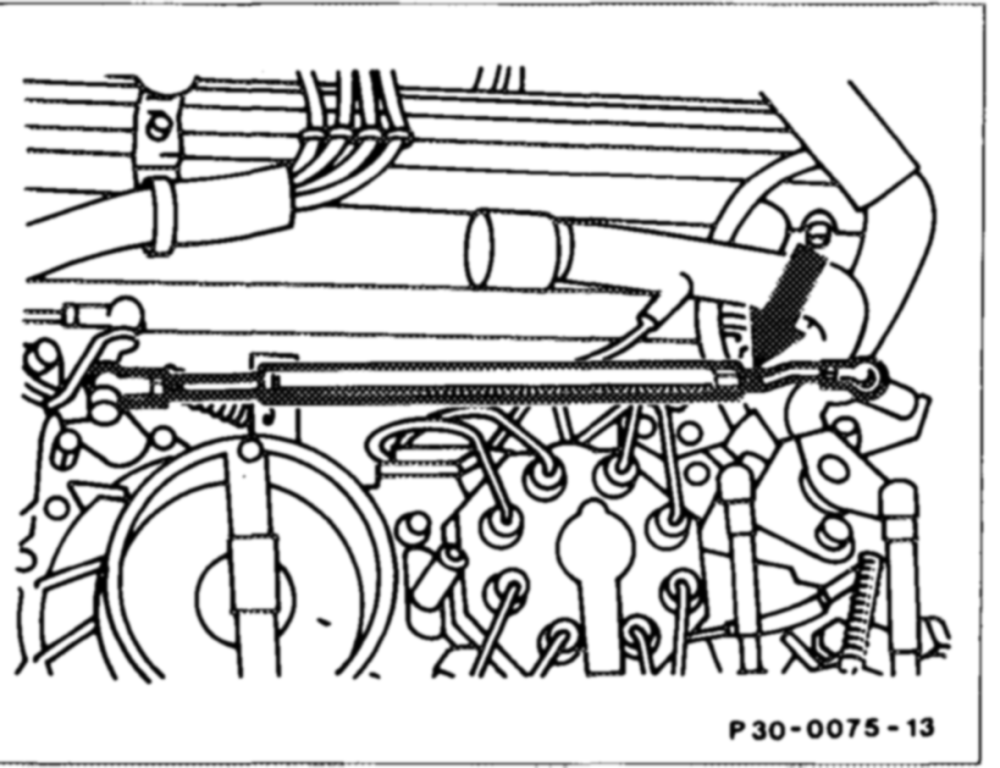
LN The length of the idle travel rod may only be adjusted at the knurled edge (arrow).
On no account, may the ball sockets be detached and shifted.
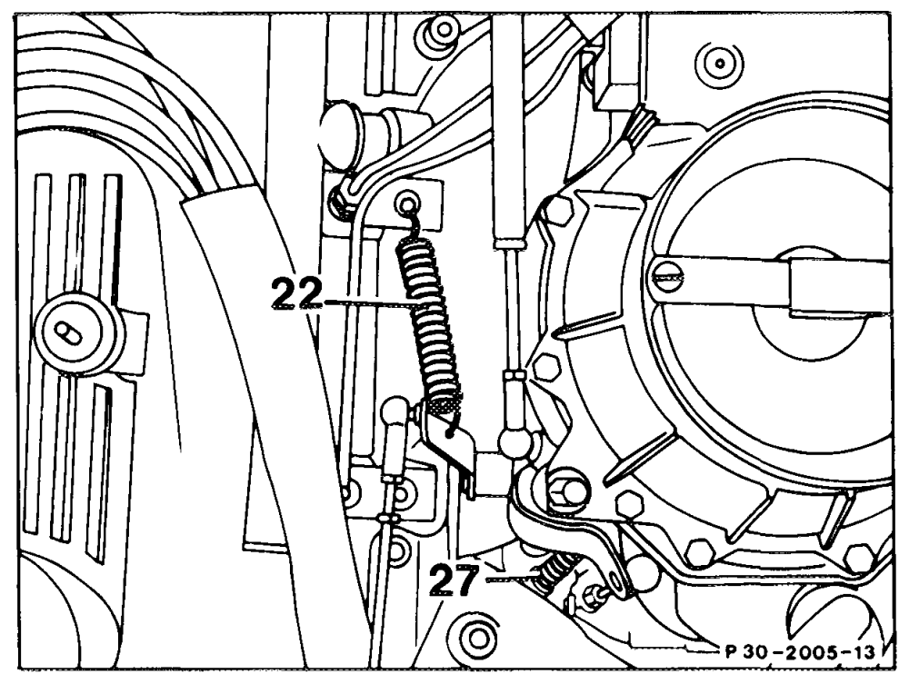
relay lever and potentiometer relay lever are identical. They must not be mixed up with the return spring on the throttle valve.
22 Return spring 27 Throttle valve return spring