Testing starting valve control
WIS 07.3-126
038
A 003 = FA €
P07-0096–53
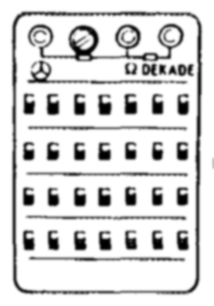
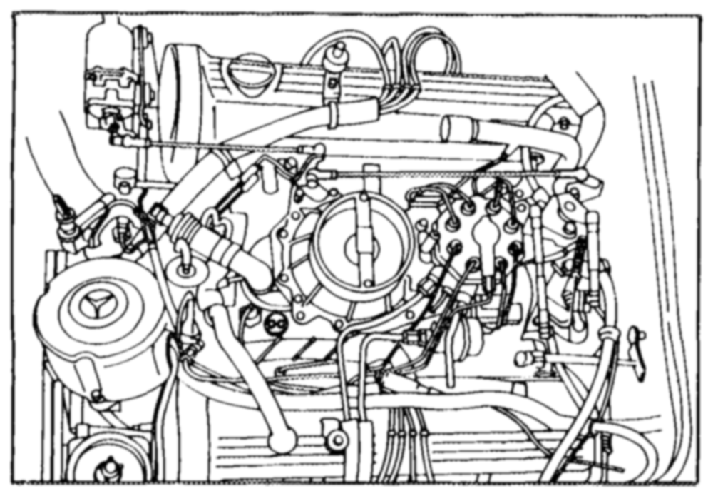
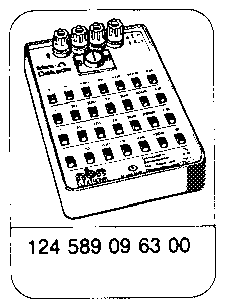
TesterS ee eee connect: Multimeter (003) Q decade (038) 124 589 09 63 00. Starting voltage 6. ww eee test. At least 10 V in approx. 5 seconds. Electric cables between starting valve and fuel pump relay 2.0.0.0… 0. eee eee test for continuity. Resistance approx. 0 2. Voltage at fuel pump relay …………..00. test. Contact 12 (terminal 50) at least 10 V, contact 2 (terminal TF) 3 – 5 V simulated at 10 kQ.
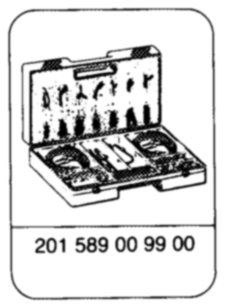
Special tools
Joy
Commercial testers e.g. Sun, DMM-5 Multimeter
Note Wiring diagrams (07.3-128).

Operation/ Possible cause/Remedy Requirement
2-pole coolant
temperature
(B11/2): Create intermediate contacts with Q coolant temperature sensor (B11/2) simulate 10 kQ
4-pole coolant
temperature
(B11/2): Connect lambda diagnostic socket Switch on ignition. Readout 70 %. coolant temperature sensor connector readout 30 %. Simulate 10 kQ decade at temperature sensor connector (B11/2), establish intermediate contacts diagonally lambda tester %. Plug protective No. 102 589 onto diagnostic
Start engine. Fuel pump relay (N16/4), wiring TF signal (07.3-112, test steps 5.0 – 5.2).
Open circuit pump relay disconnected. Starter (M1) — N16/4
pump relay Open circuit disconnected, starting valve disconnected.
Connector at Open circuit disconnected.