Testing, adjusting engine
WIS 07.3-110
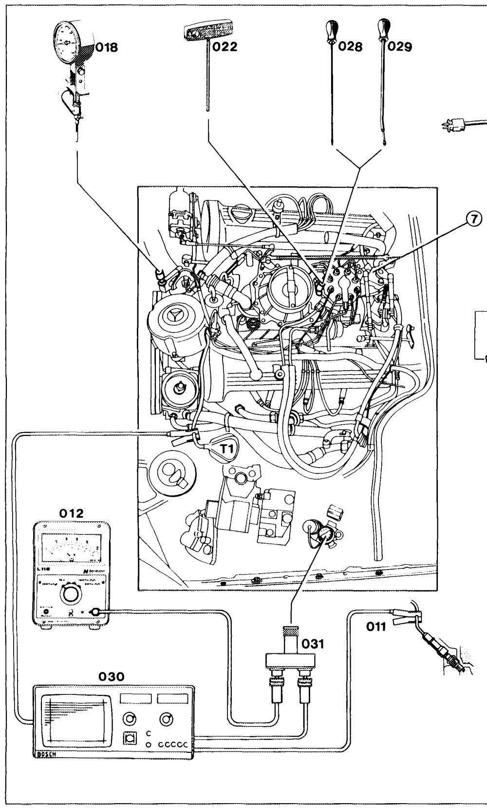
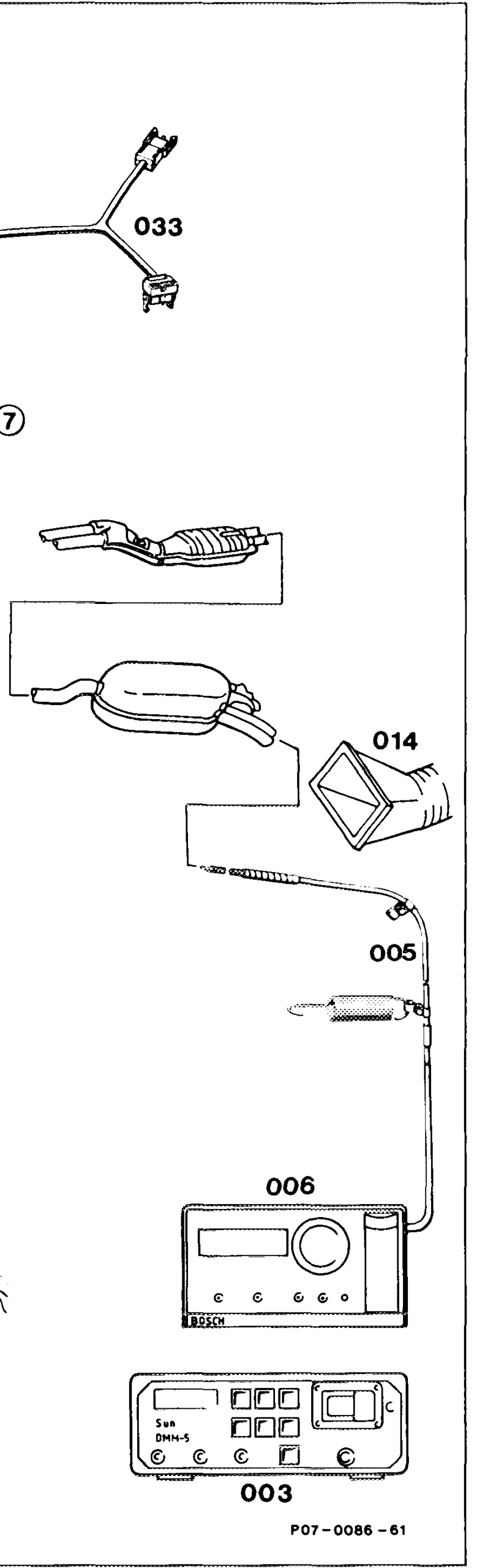
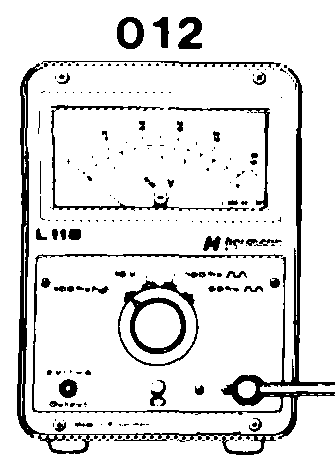
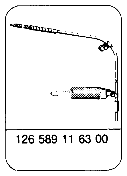
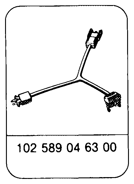
AC or automatic climate control …………. switch off. Selector lever 2.0… 02… ce eee move into position „P”. Testers ee eee connect: Telethermometer (018) 124 589 07 21 00, Lambda control tester (012), Twin outlet (031), Trigger clamp (011), Exhaust sensor (005) 126 589 11 63 00, CO analyzer (006), Engine tester with oscilloscope (030), Multimeter (003), Test cable (033) 102 589 04 63 00. position at exhaust tail pipe. Extraction device (014) 0.000. Coolant level 2.2… 20.20.0000… 00000000004 check, adjust to correct level. Engine oillevel 0.002 eee eee check, pay attention to condition of oil (visual inspection). Airfilter 0. eee remove, install. check throttle valve for ease of movement and Accelerator control linkage (7) …………– condition. Grease bearing points, relay levers, ball sockets. Variable-fulcrum lever 0.0.0.0. 00000 e check, adjust. Idle stop we ee check.
Full throttle stop 2… eee eee check, adjust from accelerator pedal. Current at actuator»… 2.1… ee eee test with ignition switched on. Ignition timing …………….22.2220005 test, adjust (refer to table). Vacuum adjustment 000000 eee check (refer to table). Oil level in automatic transmission ……….. check, adjust to correct level. approx. 80 °C. Engine oil temperature …………..0005. Oscilloscope image 0.0 eee eee analyze. Intake systeM 20… ee ee test for leaks by spraying. Operation of electrical components ……….. check. EGR valve 2… ee eee check.
Idle speed 1… eee check (refer to table).
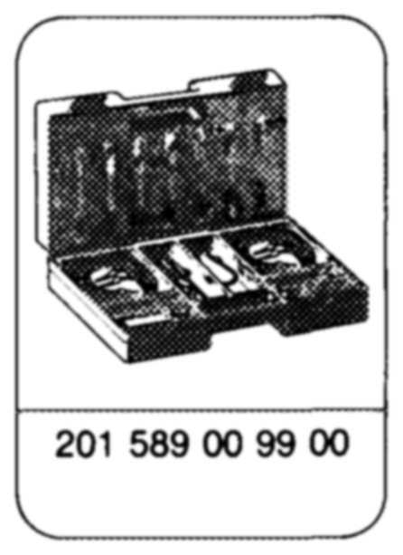
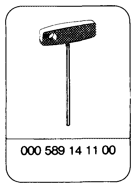
For resetting, use special tools,
screwdriver (022) 000 589 14 11 00,
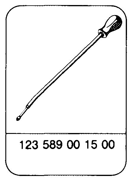
extractor (028) 123 589 05 33 00, fitting mandrel (029) 123 589 00 15 00. Engine running check by switching on all ancillaries.
Test and Adjustment Data
Engine Model Year Lambda Control Idle speed in rpm
116.965 1986-> 660 300 ’)2)
650 wo ’)2)” 117.967 1986 >
117968 —-1986 > 650° ’)2) a
1) 1986/87 Test jambda control at 2500 rpm and take average reading; detach purge line at electric switchover vaive for this test and seal. Compare this reading with idle speed level. The average at idle speed must be greater than 5, but not more than 15, than the level measured at 2500 rpm. 2) starting 1988 Test lambda control at 2500 rpm and take average reading; detach purge line at electric switchover valve for this test and seal. Compare this reading with idle speed level. The average at idle speed must not vary by more than +10 from the reading measured at 2500 rpm.
Ignition timing
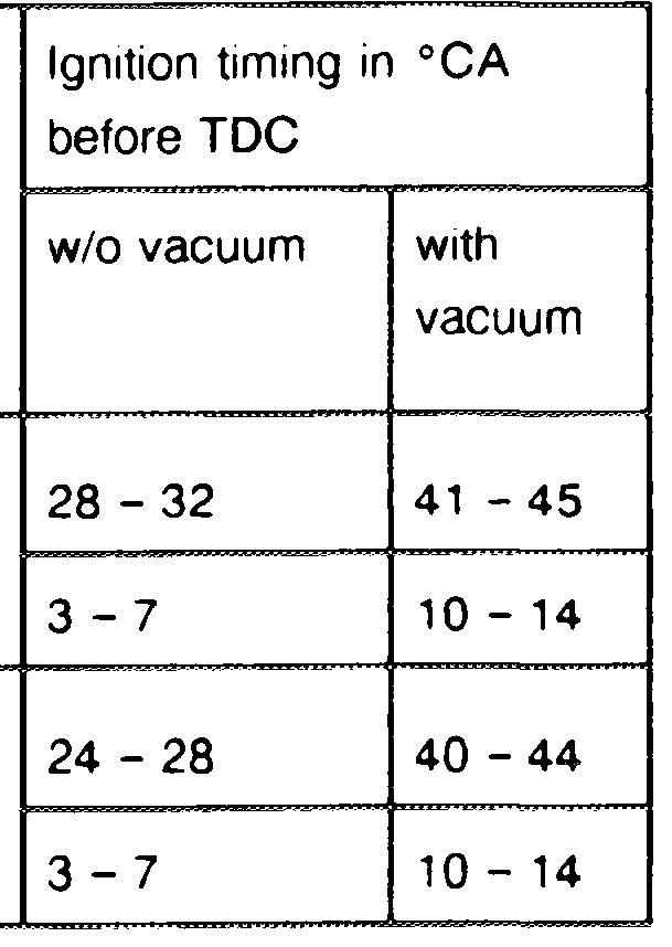
Engine Electronic Ignition Model Year Engine Reference resistor Control Unit speed in Part No. rpm
116.965 4986–91 003 5459132 3500 750 2
003 545 92 32 Idle
117.967 1986–91 004 545 53 32 3500 750 2 117.968 we 004 545 55 32 Idle
Version Current at actuator mA
75
Special tools

Commercial testers
| CO analyzer | —_ | ||
| Engine tester (engine speed, dwell angle, ignition angle, oscilloscope, voltmeter) | e.g. | Bosch, MOT 002.02 Sun, 1019 | |
| Lambda contro! tester | e. g. | Hermann, | L 115— |
| a oe oe Multimeter | eg. “Sun, DMM-5 | 7 | |
| oe Twin outlet | e. 9. | Hermann, | a ECD ¢ 53 |
Shop-made tool
| Intake pipe DIN 19534 ND 125 for air flow sensor | Length approx. 500 mm |
| seal | @. g. from air filter |
Note Test and adjust lambda control with a lambda control tester.
The lambda control or the idle emissions level must not be tested and set when the engine is hot, e. g. immediately after driving sharply or after measuring engine output on the dynamometer.
Testing, adjusting
1 Complete test sheet.
2 Switch off air conditioning system or automatic climate control. Move selector lever into position „P”.
3 Connect testers: Telethermometer (018) 124 589 07 21 00 Lambda control tester (012) Twin outlet (031) Trigger clamp (011) Exhaust probe (005) 126 589 11 63 00 CO analyzer (006) Engine tester with oscilloscope (030) Multimeter (003) Test cable (033) 102 589 04 63 00.
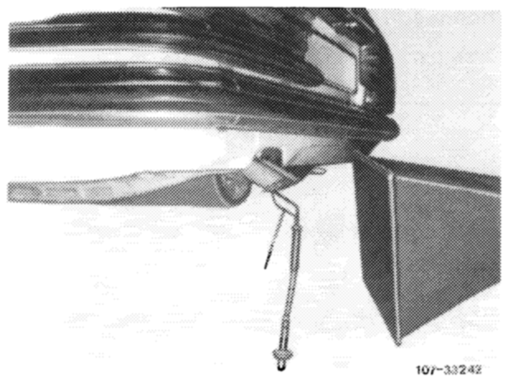
4 Position extraction device (014) at exhaust tail pipe.
5 Check coolant level, adjust to correct level.
6 Check engine oil level, paying attention to condition of oil (visual inspection).
7 Remove air filter.
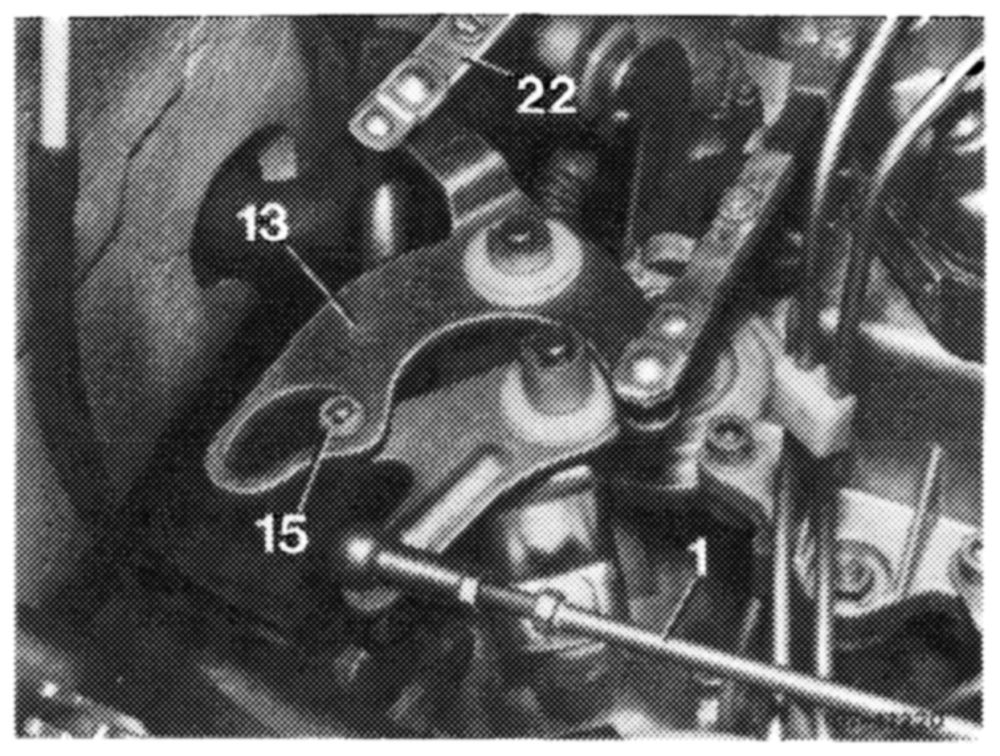
8 Check accelerator control linkage and throttle valve for condition and ease of movement. Grease all bearing points and ball sockets.
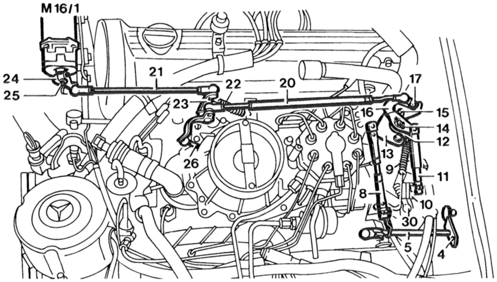
9 Engines without ASR: Check variable-fulcrum lever, adjust. Check whether the roller (15) in the variable-fulcrum lever (13) is resting free of tension against the end stop. Adjust variablefulcrum lever (13) with the connecting rod (1), if necessary, so that the roller (15) is resting free of tension against the end stop.
Engines with ASR: Switch on ignition. Relay lever potentiometer (12) must be resting against idle stop. Accelerator control lever (16) must be resting on the outer curved track of the variable-fulcrum lever (13). Adjust accelerator control (30-300).
1073 -15 374
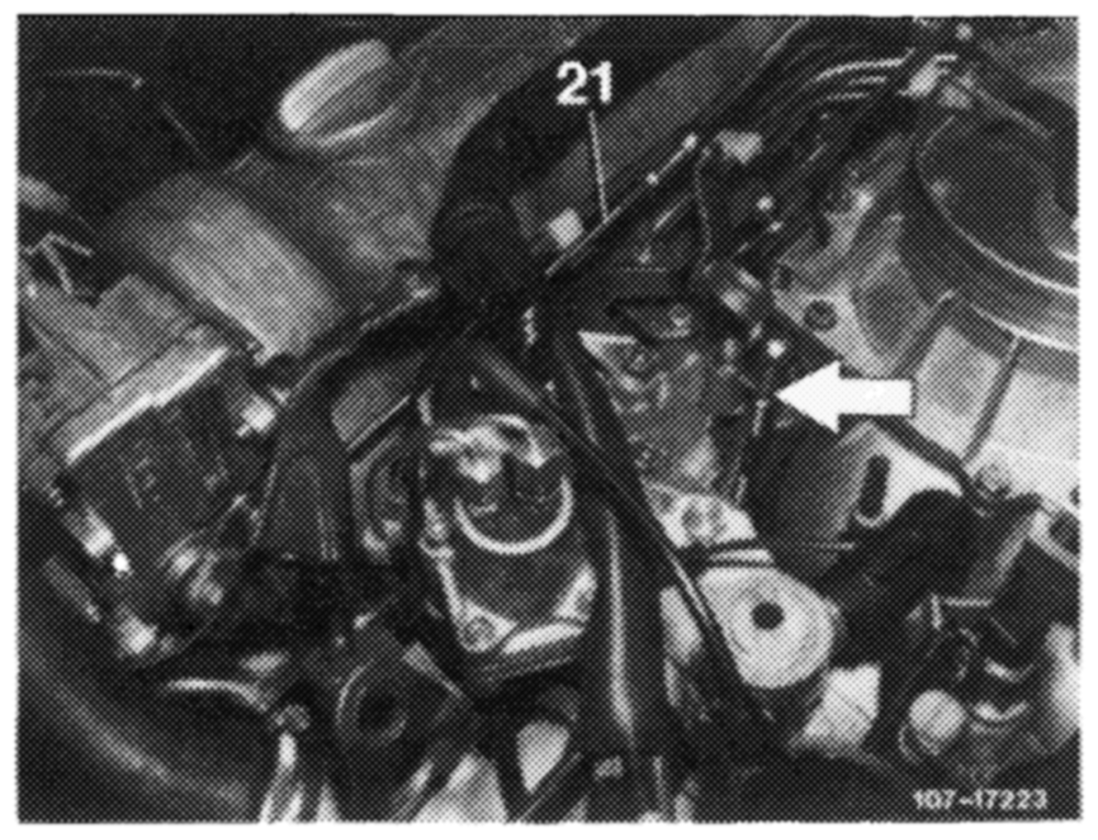
10 Idle stop. Check whether the throttle valve is resting against idle stop by detaching connecting rod (arrow). Adjust accelerator control (30-300).
Engines with cruise control only, without ASR: Check whether the actuator is resting against idle stop of cruise control by pressing lever of actuator clockwise onto idle stop at cruise control. When attaching the connecting rod (21), ensure that the lever of the actuator is raised by approx. 1 mm off the idle stop at the cruise control. Adjust tie rod, if necessary. Adjust accelerator control (30-300).
Engines without ASR: Check full throttle stop from accelerator pedal, adjust (30300).
Engines with ASR: Switch on ignition. Deflect variable-fulcrum lever (13) fully and hold in this position. Check at throttle valve assy. whether throttle valve is resting against full throttle stop without linkage being over-tensioned. Adjust accelerator control (30-305).
12 Test voltages (battery and ignition coil):
No-load voltage
Connect voltmeter, paying attention to polarity at battery, and take voltage reading. Specification: 12.2 Volts
Ignition coil
Engine not running, switch on ignition. Test voltage of terminal 15 to ground at contact 5 of diagnostic socket. Specification: battery voltage Test voltage difference between terminal 15 and terminal 1 at contacts 5 and 4 of diagnostic socket. Specification: 0 Volts If the specified voltages are not reached, test ignition system (15-540 or 15-541).
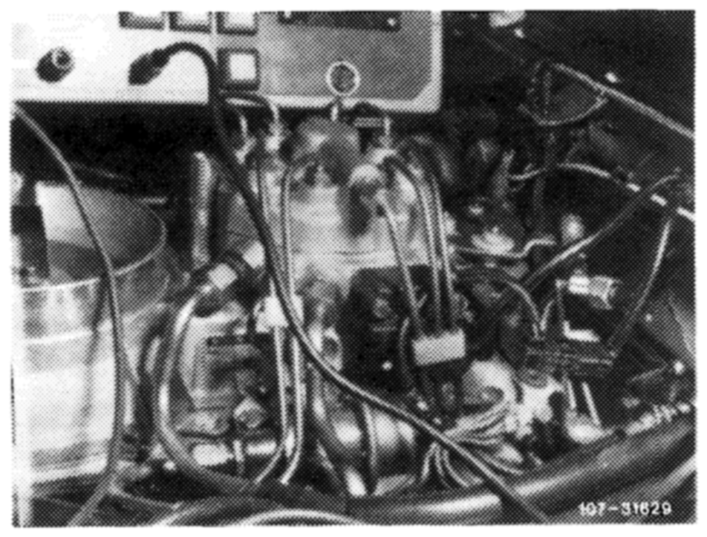
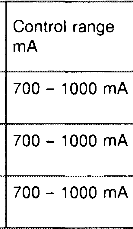
switched on by detaching connector at actuator and connecting test cable 102 589 004 63 00 into circuit. Connect multimeter and set to mA.
Current at Version actuator mA
75
If the specified amperages are not reached, perform test routine (07.3-121).
14 Test ignition timing and vacuum adjustment (refer to table). If the specified levels are not reached, test ignition system (15-540 or 15-541).
15 Check oil level in automatic transmission.
16 Run engine until oil temperature approx. 80 °C.
17 Analyze oscilloscope image (15-525).
18 Check intake system for signs of leaks. Before spraying, fit shop-made intake pipe to air flow sensor. Spray all sealing points with isooctane DIN 51 756 or cleaning petroleum. CO increase <2 %.
AN Do not use commercial fuel for spraying (harmful vapors). Pay attention to risk of fire and do not spray onto red hot parts or parts of the ignition system.
To determine the CIS-E control unit, switch on ignition and measure on/off ratio.
| ratio % | Version Control unit without fault diagnosis by measuring on/off ratio ’) |
| % | CIS-E control unit with fault diagnosis by measuring on/ off ratio |
| % | California eff. 1988 CIS-E control unit with fault memory for on-board diagnosis system |
1) Certain cars only at start of series production through to production date 551 in CIS-E control unit. 2) Starting date of production 552 the microprocessor for fault detection is integrated in the CIS-E control unit.
Engines with fault diagnosis by measuring
on/off ratio
Operational check of idle and full load contact.
Specifications:
Idle contact:
Switch on ignition, on: off ratio readout 70 %. Deflect air flow sensor plate, on/off ratio readout 10 %, if readout 70 % test throttle valve switch (07.3-121).
Full load contact:
Switch on ignition, onioff ratio readout 70 %. Open throttle valve fully, onoff ratio readout 20 °%, if readout 40 % test air flow sensor potentiometer (07.3-121).
measuring on/off ratio
Start engine when at normal operating temperature. Engine running at idle speed. If readout does not flucuate, perform test routine (07.3-121).
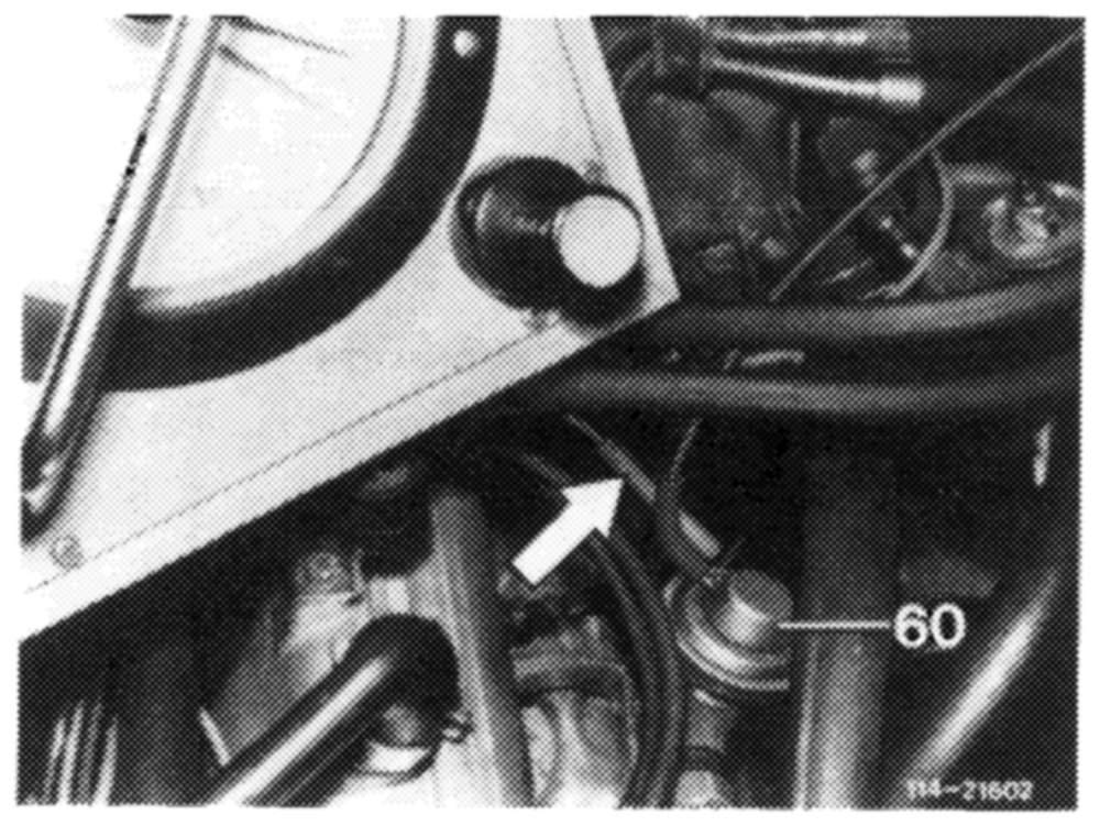
20 Check operation of exhaust gas recirculation valve. Detach vacuum line (arrow) at EGR valve (60), connect tester to EGR valve and pressurize with vacuum. If engine running does not significantly deteriorate, renew EGR valve. Check control mechanism, if necessary (14-475).
21° Install air filter.
22 Test idle speed (refer to table).
Note
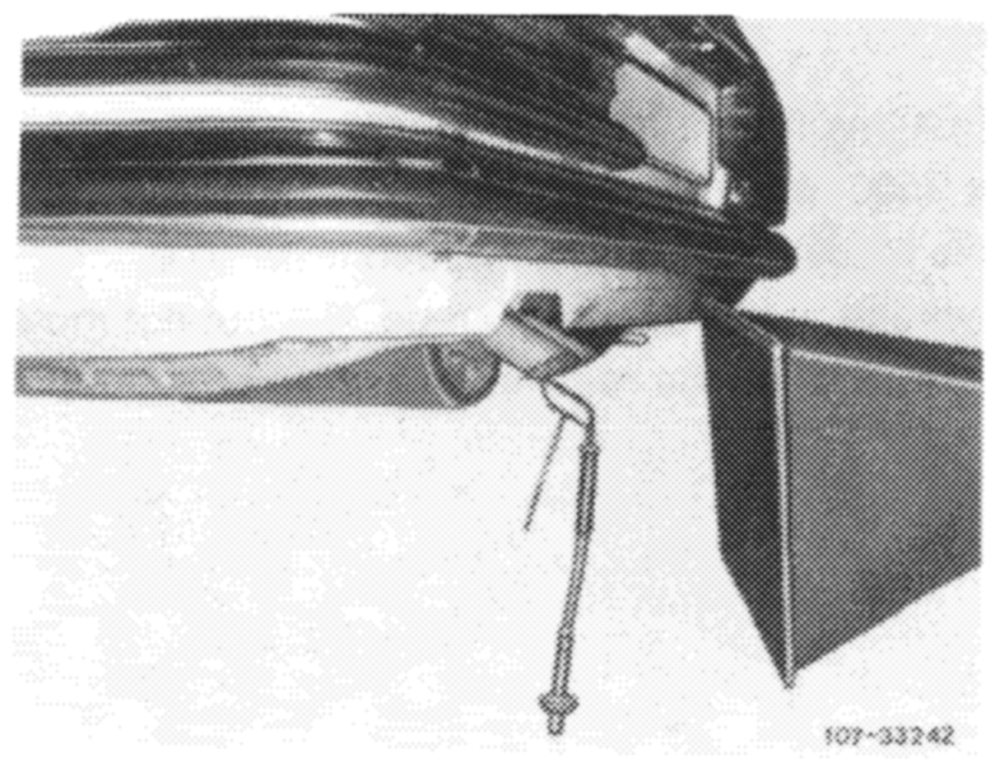
If engine fitted with electronic idle speed control, idle speed cannot be adjusted. If idle speed varies from specification, test electronic idle speed control (07.3-112).
23 Test idle emissions level (refer to table). This is measured at exhaust tail pipe. Set idle emissions level (refer to step 24).
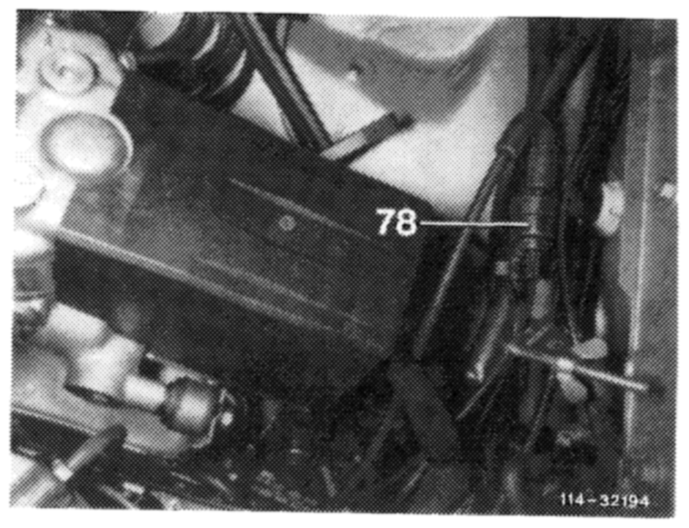
purge line to throttle valve assy. at purge valve (78) and seal. Press test signal selector of Hermann lambda control tester to position 100 % A), or press 100 % IR button on Bosch tester.
Set lambda control (refer to step 24).
Note The readout must fluctuate during the measurement. If a constant readout is indicated. there is a fault in the lambda control, e. g. O2 sensor disconnected.
Refer to „Testing electrical components of CIS-E injection system” (07.3-121) for troubleshooting table.
Test onioff ratio of 1988–91 cars at 2500 rpm and take average reading. Compare this reading with the idle speed level. The average at idle speed must not vary by more than +10 from the reading measured at 2500 rpm.
Test on/off ratio of 1986/87 cars at 2500 rpm and take average reading. Compare this reading with the idle speed level. The average at idle speed must be >5, but not more than 15, than the reading measured at 2500 rpm.
073.0711 – 110/12
(refer to table).
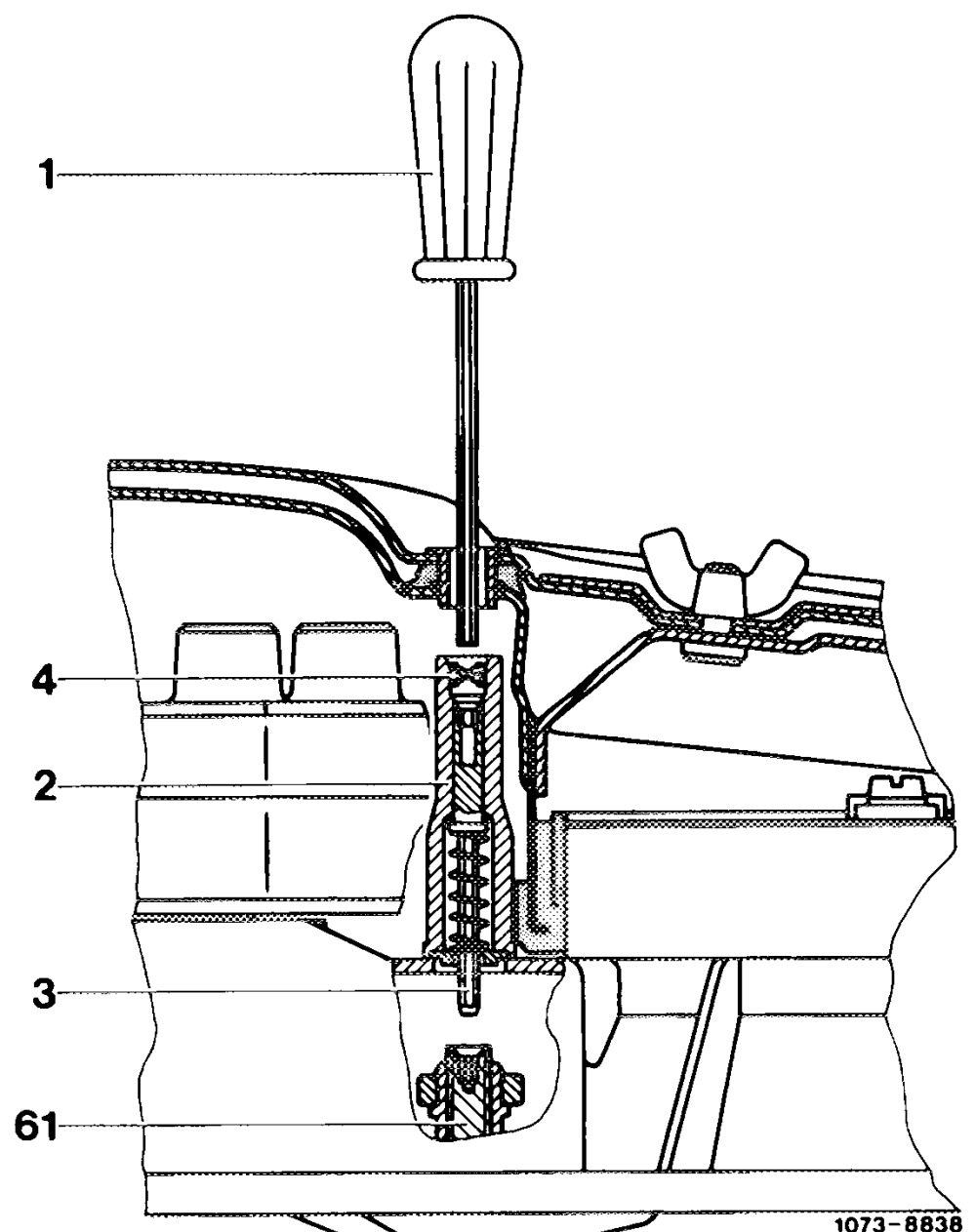
Withdraw security plug (4) with the extractor.
Press the screwdriver (1) through the recess on the top section of air filter onto the adjusting device (2). Press the adjusting device down with the screwdriver against to the spring force, turn it slightly until the hex head (3) engages in the mixture adjusting screw (61).
Turn to the left for leaner mixture — on/off ratio
increases Turn to the right for richer mixture — on/off ratio drops
Screwdriver = FON Adjusting device Hex head Security plug Mixture adjusting screw a
After each adjustment, depress accelerator pedal briefly; reset, if necessary.
After adjusting, insert a blue security plug (4), Part No. 000 997 59 86, with the fitting mandrel.
Reconnect purge line (only if lambda control fitted).
26 Test engine running by moving selector lever into Drive position, switching on air conditioning system/automatic climate control, and turning power steering to full lock. Engine must run smoothly.