Electrical wiring diagrams
WIS 07.3-128
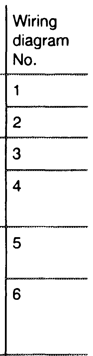
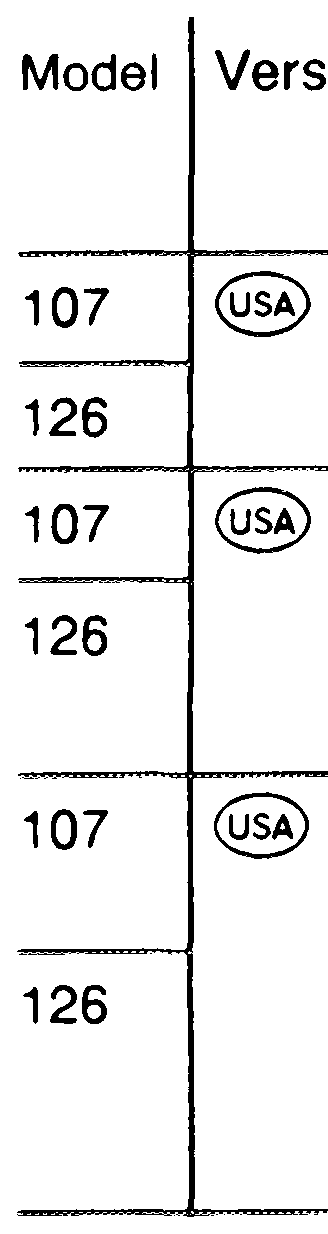
The following wiring diagrams of the mechanical/electronic gasoline injection system with automatic transmission and A/C compressor are shown.
Remark
| up to 1986/87 | |
| Federal as of 1988 | Separate reference resistor (R17/1) eliminated, now integrated in CIS-E control unit. Indicator lamp “CHECK ENGINE”. |
| California as of 1988 | Separate reference resistor (R17/1) eliminated, now integrated in CIS-E control unit, Indicator lamp „CHECK ENGINE” and on-board diagnosis. Coolant temperature sensor 4-pole. |
Unmarked grounding points on ground engine or ground body. The ground lead from plug 2 is connected with plug 7 in the control unit CIS-E (N3)..
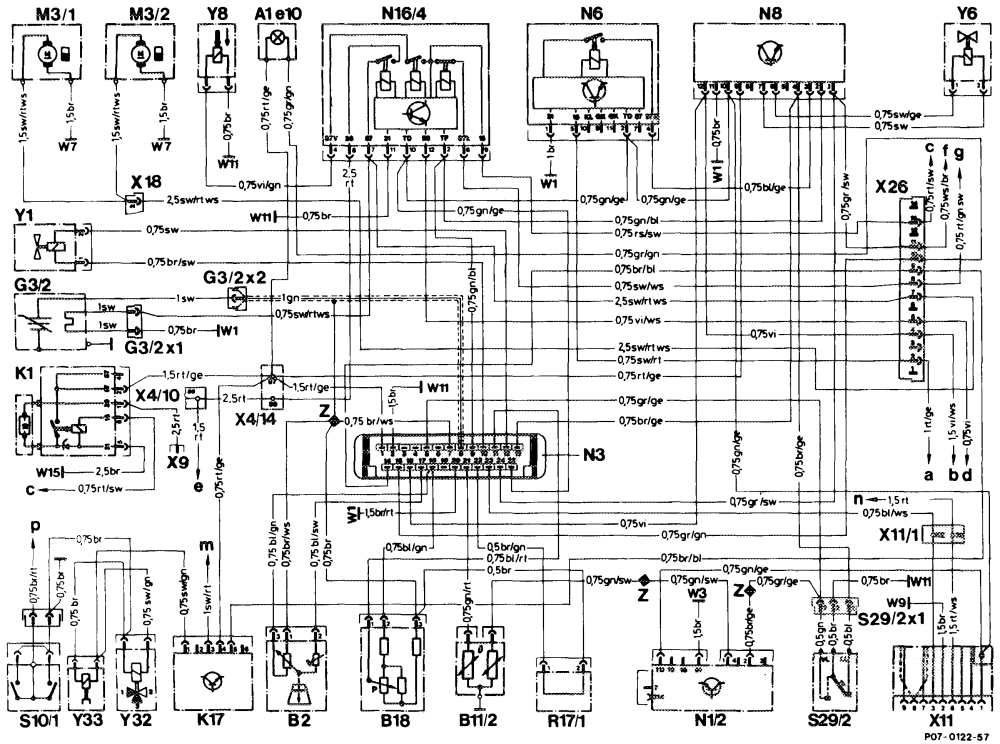
Engine 117 1986/87 model 107
Wiring diagram No. 1
Connector, terminal 30 (1-pole) O2-sensor indicator lamp x9 A1e10 Diagnostic socket/terminal block (circuit TD) B2 Air flow sensor position indicator X11 Coolant temperature sensor (EZL/CIS-E)(2-pole) B11/2 x11/1 Diagnostic socket/terminal block, terminal 30/CIS-
E (2-pole)
Connector, interior/tail lamp harness B18 X18 Altitude correction capsule Connector, interior/engine G3/2 Heated O2-sensor X26 G3/2×1 Connector, O2-sensor heater coil (2-pole) Electrohydraulic actuator (EHA) Y1 G3/2×2 Connector, O2-sensor signal (1-pole) Y6 Idle speed air valve Start valve Overvoltage protection relay (5-pole) K1 Y8 Y32 Air injection pump switchover valve K17 Air injection relay Electromagnetic air injection pump clutch Fuel pump 1 Y33 M3/1 Connector sleeve (solder joint in harness) M3/2 Fuel pump 2 Electronic ignition control unit (EZL) Fuse and relay box F1, fuse 6, terminal 15X N1/2 ooo CIS-E control unit Ignition starter switch S2/1, terminal 50 N3 A/C compressor contro! unit Fuse and relay box F1, fuse 7, terminal 15 N6 unprotected side N8& Idle speed control unit Connector starter cable harness X27, jack 2 Fuel pump relay with kickdown cut-out N16/4 Qa Reference resistor (CIS-E) R17/1 (starter terminal 50) $10/1 Left front brake pad wear sensor Fuse and relay box F1, fuse 12, terminal 30 $29/2 Throttle valve switch, full load/idle unprotected side Terminal block X21/1, brake light $29/2×1 Connector, throttle valve switch, full load/idle Ww1 Main ground (behind instrument cluster) switch/electronic speedometer Connector X49/2 starter lockout and back-up Ground, left front wheel housing (at ignition coil) Ww3 Ground, right rear wheel housing in trunk W7 light switch jack 7 (kickdown S16/6) Ground, at left headlamp unit Fuse and relay box F1, fuse 7, terminal 15 w9 Ground, engine (connection point for ground Fuse and relay box F1, fuse 12, terminal 30 W111 2 Instrument cluster A1 coupling 15-pole, jack 7 wires) Ground, electronics (right footwell) W15 Terminal block, terminal 30/terminal 61 (battery) X4/10 X4/14 Terminal block, terminal 87/terminal 30 (2-pole)
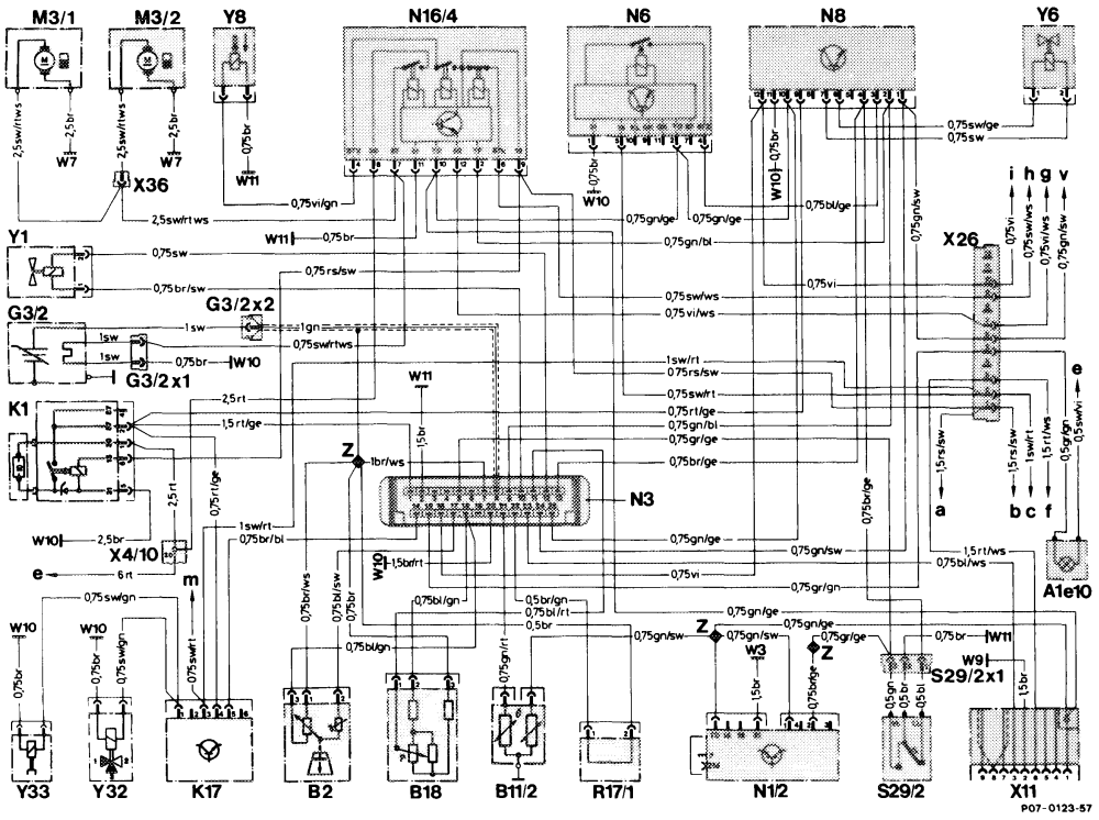
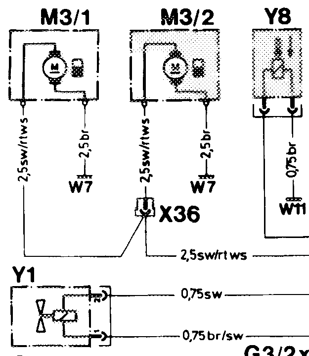
Engines 116, 117 1986/87 model 126
Qe-sensor indicator lamp Connector, interior/engine A1e10 X26 B2 Connector, fuel pump harness (1-pole) Air flow sensor position indicator X36 Coolant temperature sensor (EZL/CIS-E)(2-pole) B11/2 Electrohydraulic actuator (EHA) Y1 Y6 Idle speed air valve Start valve B18 Altitude correction capsule Y8 G3/2 Heated O2-sensor Air injection pump switchover valve Y32 Connector, O2-sensor heater coil (2-pole) G3/2×1 Electromagnetic air injection pump clutch Y33 G3/2×2 Connector, O2-sensor signal (1-pole) Connector sleeve (solder joint in harness) Overvoltage protection relay (5-pole) K1 Ignition coil terminal 15 Fuse and relay box F1, fuse 7, terminal 15 K17 Air injection relay Fuel pump 1 unprotected side M3/1 M3/2 Fuel pump 2 Fuse and relay box F1, fuse 5, terminal 15 Terminal block X4/1, terminal 30 (fuse and relay Electronic ignition control unit (EZL) N1/2 CIS-E control unit N3 box) A/C compressor control unit Fuse and relay box F1, fuse 2, terminal 30 N6 Idle speed control unit Connector starter cable harness X27, jack 2 N8 Fuel pump relay with kickdown cut-out N16/4 (starter terminal 50) Reference resistor (CIS-E) Connector X49/2 starter lockout and back-up R17/1 $29/2 Throttle valve switch, full load/idle light switch jack 7 (kickdown $16/7) Connector, throttle valve switch, full load/idle $29/2×1 Ignition starter switch S2/1, terminal 50 Ground, left front wheel housing (at ignition coil) Auxiliary fan relay (K9) jack 4, terminal 86 W3 Ground, right rear wheel housing in trunk Speed signal electronic speedometer A1p8 W7 < Ground, at left headlamp unit wg Ground, engine (connection point for ground wii wires) X4/10 Terminal block, terminal 30/terminal 61 (battery) X11 Diagnostic socket/terminal block (circuit TD)
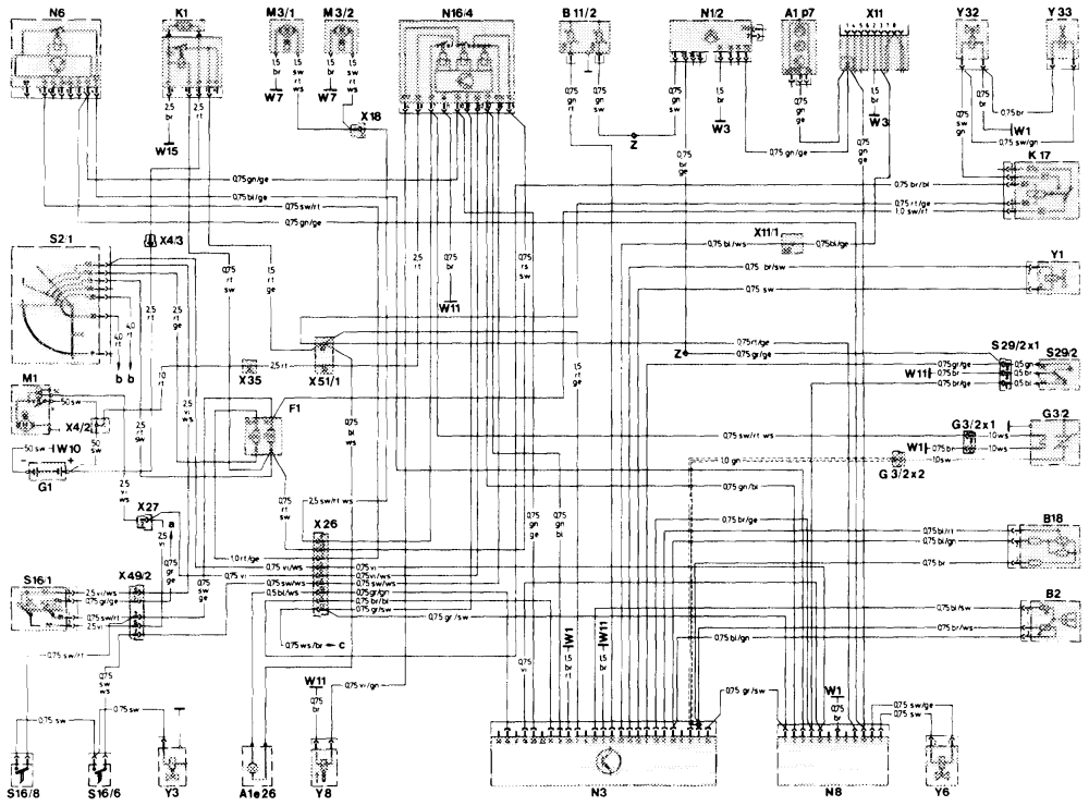
Wiring diagram No. 3 Engines 116, 117 Federal as of 1988 model 107
P07-0292–61
07.3.0712-128’6
Wiring diagram No. 3 Main ground (behind instrument cluster) W1 „CHECK ENGINE” warning lamp A1e26 Ground, left front wheel housing (at ignition coil) W3 Electronic clock/tachometer A1p7 Ground, right rear wheel housing in trunk W7 Air flow sensor position indicator B2 Ground, battery W10 Coolant temperature sensor (EZL/CIS-E)(2-pole) B11/2 Ground, engine (connection point for ground wii wires) Altitude correction capsule B18 Ground, electronics (right footwell) W15 Fuse and relay box FA Terminal block, terminal 30 (2-pole) X4/2 Battery G1 Connector, terminal 30, battery/overvoltage X4/3 Heated O2-sensor G3/2 protection (1-pole) Connector, O2-sensor heater coil (2-pole) G3/2×1 Diagnostic socket/terminal block (circuit TD) x11 Connector, O2-sensor signal (1-pole) G3/2×2 Diagnostic socket/terminal block, terminal 30/CISx11/1 Overvoltage protection relay (5-pole) K1 E (2-pole) Air injection relay K17 Connector, interior/tail lamp harness x18 Starter M1 Connector, interior/engine X26
Fuel pump 1
M3/1 Connector, starter harness X27 Fuel pump 2 M3/2 Terminal block, terminals 30/61 (battery) (— X35 Electronic ignition control unit (EZL) N1v/2 X4/10—) CIS-E control unit N3 Connector, backup lamp/starter lock-out switch X49/2 A/C compressor control unit N6 Electrohydraulic actuator (EHA) v1 \dle speed control unit N8 Kickdown valve (automatic transmission) Y3 Fuel pump relay with kickdown cut-out N16/4 Idle speed air valve Y6 Ignition/starter switch $2/1 Start valve Y8 Starter lock-out/backup lamp switch $16/1 Air injection pump switchover valve Y32 Kickdown switch S16/6 Electromagnetic air injection pump clutch Y33 “B” engagement switch $16/8 Connector sleeve (solder joint in harness) Throttle valve switch, full load/idle $29/2 Lamp control unit jack 13 Connector, throttle valve switch, full load/idle ooo $29/2×1 Rotary light switch Electronic speedometer
Po7-0204–61
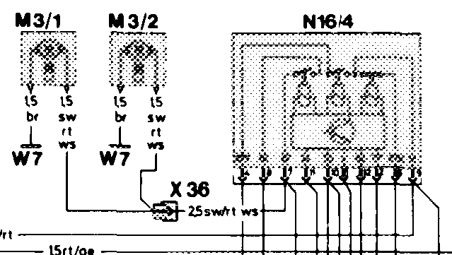
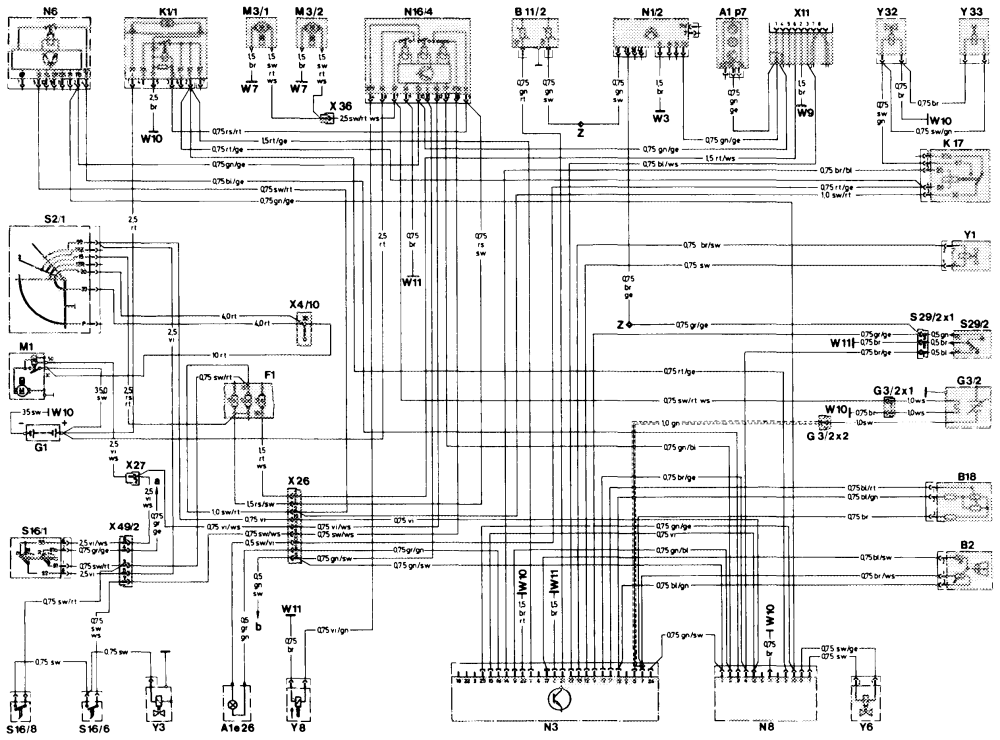
Wiring diagram No. 4
„CHECK ENGINE” warning lamp Connector, throttle valve switch, full load/idle A1e26 $29/2×1 Electronic clock/tachometer Ground, left front wheel housing (at ignition coil) Alp7 W3 Ground, right rear wheel housing in trunk B2 Air flow sensor position indicator W7 Coolant temperature sensor (EZL/CIS-E)(2-pole) B11/2 Ground, at left headlamp unit ws Ground, battery W10 Ground, engine (connection point for ground B18 Altitude correction capsule wi1 FI Fuse and relay box wires) G1 Battery X4/10 Terminal block, terminal 30/terminal 61 (battery) G3/2 Diagnostic socket/terminal block (circuit TD) Heated O2-sensor X11 G3/2×1 Connector, O2-sensor heater coil (2-pole) X26 Connector, interior/engine Connector, O2-sensor signal (1-pole) G3/2×2 Connector, starter harness X27 Overvoltage protection relay, 87E (7-pole) Connector, fuel pump harness (1-pole) K1/1 X36 Connector, backup lamp/starter lock-out switch K17 Air injection relay X49/2 Starter Electrohydraulic actuator (EHA) M1 Y1 Kickdown valve (automatic transmission) M3/1 Fuel pump 1 Y3 M3/2 Fuel pump 2 Y6 Idle speed air valve Electronic ignition control unit (EZL) Start valve N1/2 Y8 CIS-E control unit Air injection pump switchover valve N3 Y32 Electromagnetic air injection pump clutch N6 A/C compressor control unit Y33 Connector sleeve (solder joint in harness) N8& Idle speed control unit N16/4 Fuel pump relay with kickdown cut-out Lamp control unit jack 13 S21 Ignition/starter switch Jack electronic speedometer Starter lock-out/backup lamp switch $16/1 S16/6 Kickdown switch $16/8 “B” engagement switch $29/2 Throttle valve switch, full load/idie
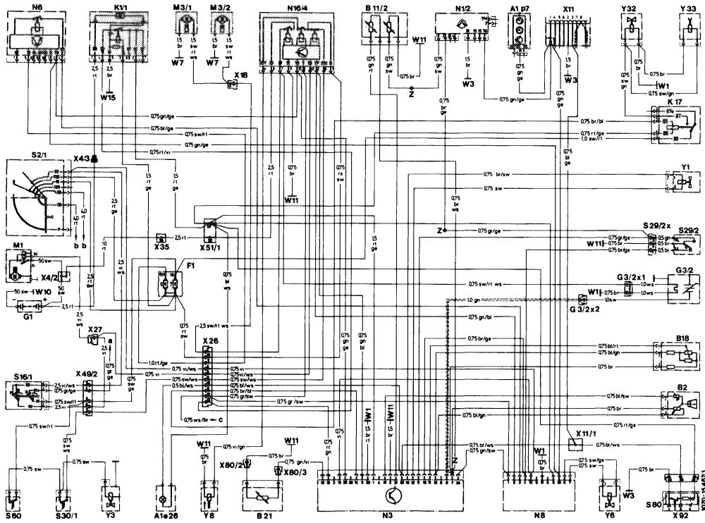
Engines 116, 117 California as of 1988 model 107
1070–15 467/1
„CHECK ENGINE” warning lamp A1e26 W10 Ground, battery A1p7 Electronic clock/tachometer Ground, engine (connection point for ground W11 B2 Air flow sensor position indicator wires) B11/2 Coolant temperature sensor (EZL/CIS-E)(4-pole) W15 Ground, electronics (right footwell) B18 Altitude correction capsule x4/2 Terminal block, terminal 30 (2-pole) EGR temperature sensor B21 X4/3 Connector, terminal 30, battery/overvoltage Fi Fuse and relay box protection (1-pole) G1 Battery X11 Diagnostic socket/terminal block (circuit TD) Heated Oo-sensor G3/2 X11/1 Diagnostic socket/terminal block, terminal 30/CISConnector, O2-sensor heater coil (2-pole) G3/ex1 E (2-pole) Connector, O2-sensor signal (1-pole) G3/2×2 X18 Connector, interior/tail lamp harness Overvoltage protection relay, 87E (7-pole) K1/1 X26 Connector, interior/engine K17 Air injection relay Connector, starter harness X27 Starter M1 X35 Terminal block, terminal 30/terminal 61 (battery) M3/1 Fuel pump 1 X51/1 Terminal block, terminal 87/terminal 30 (2-pole) M3/2 Fuel pump 2 x49/2 Connector, backup lamp/starter lock-out switch N1vV/2 Electronic ignition control unit (EZL) Connector, temperature sensor, EGR (referance X80/2 CIS-E control unit N3 ground) A/C compressor control unit N6 X80/3 Connector, temperature sensor, EGR (signal N8 Idle speed control unit CIS-E) Fuel pump relay with kickdown cut-out N16/4 x92 Test connection for diagnosis, (impulse readout, s2it Ignition/starter switch 8-pole) S16/1 Starter lock-out/backup lamp switch Y1 Electrohydraulic actuator (EHA) $29/2 Throttle valve switch, full load/idle Y3 Kickdown valve (automatic transmission) $29/2×1 Connector, throttle valve switch, full load/idle Y6 Idle speed air valve $30/1 Kickdown switch Y8 Start valve $60 “B” engagement switch Y32 Air injection pump switchover valve $80 Pushbutton switch with LED (California) Y33 Electromagnetic air injection pump clutch wW1 Main ground (behind instrument cluster) Connector sleeve (solder joint in harness) Ground, left front wheel housing (at ignition coil) Ww3 Lamp control unit jack 13 oon W7 Ground, right rear wheelhousing in trunk Rotary light switch Electronic speedometer
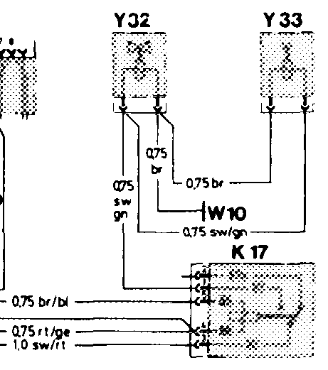
P07-0295–65
Wiring diagram No. 6
Ground, left front wheelhousing (at ignition coil) „CHECK ENGINE” warning lamp W3 A1e26 Ground, right rear wheelhousing in trunk Electronic clock/tachometer W7 A1p7 Ground, at left headlamp unit Air flow sensor position indicator wg B2 Ground, battery Coolant temperature sensor (EZL/CIS-E)(4-pole) W10 B11/2 Ground, engine (connection point for ground Altitude correction capsule wii Bi8 EGR temperature sensor wires) B21 X4/10 Terminal block, terminal 30/terminal 61 (battery) Fuse and relay box FA Diagnostic socket/terminal block (circuit TD) X11 G1 Battery Heated O2-sensor X11/4 Test connection for diagnosis, (impulse readout, G3/2 Connector, O2-sensor heater coil (2-pole) 8-pole) G3/2×1 Pushbutton switch with LED (California) Connector, O2-sensor signal (1-pole) X11/4s1 G3/2×2 Connector, interior/engine Overvoltage protection relay, 87E (7-pole) X26 K1/1 X27 Connector, starter harness Air injection relay K17 X36 Connector, fuel pump harness (1 -pole) Starter M1 Connector, backup lamp/starter lock-out switch x49/2
Fuel pump 1
M3/1 Connector, temperature sensor, EGR (reference X80/2 Fuel pump 2 M3/2 Electronic ignition control unit (EZL) ground) N1/2 Connector, temperature sensor, EGR (signal X80/3 CIS-E control unit N3 CIS-E) A/C compressor control unit N6 Y1 Electrohydraulic actuator (EHA) {dle speed control unit N8& Fuel pump relay with kickdown cut-out Y3 Kickdown valve (automatic transmission) N16/4 {dle speed air valve Ignition/starter switch Y6 $2 Y8 Start valve Starter lock-out/backup lamp switch S16/1 Air injection pump switchover valve Kickdown switch Y32 S16/6 Electromagnetic air injection pump clutch “B” engagement switch Y33 $16/8 Connector sleeve (solder joint in harness) Z Throttle valve switch, full load/idle $29/2 Connector, throttle valve switch, full load/idle Lamp control unit jack 13 $29/2×1 a b Jack, electronic speedometer