Function of fuel tank venting
WIS 47-030
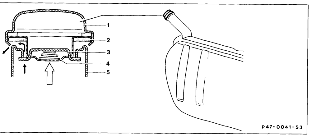
1 Filler cap 4 Compression spring
2 Seal 5 Filler neck
3 Locking clamp
An pressure of up to 50 mbar may occur in the Note fuel tank in a system which is operating The filler cap has been fitted with a plastic seal properly. If the passage in the vent line from the as a phased-in modification to facilitate operfuel tank is restricted as a result of crimping or ation. The locking bar (3) slides on this ring with improper routing, the fuel evaporation gases reduced friction and engages in the two end may escape through the filler cap at an positions. pressure of 100-300 mbar.
B. Model 107
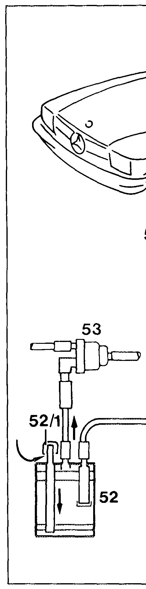
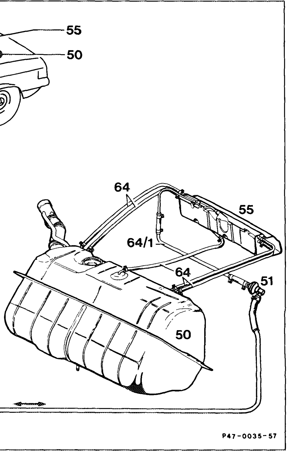
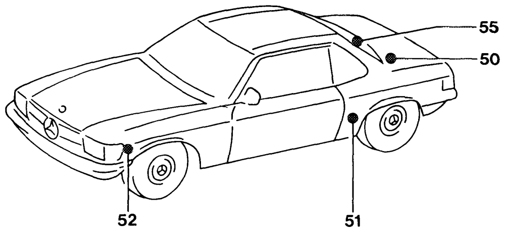
A separate fuel expansion tank (55) is located
Note Function of fuel evaporation control system above the fuel tank which is connected by five lines (64) to the fuel tank. Depending on the (47-200). Checking fuel evaporation control system fuel level and temperature in the fuel tank, these lines act as overflow, discharge or vent (47-300). lines. The vent line (64/1) runs from the fuel expansion tank (55) through the rear flow to the vent valve (51). Air is admitted to, and released from the fuel tank through the vent cap (52/1) of the charcoal canister (52).
C. Models 126
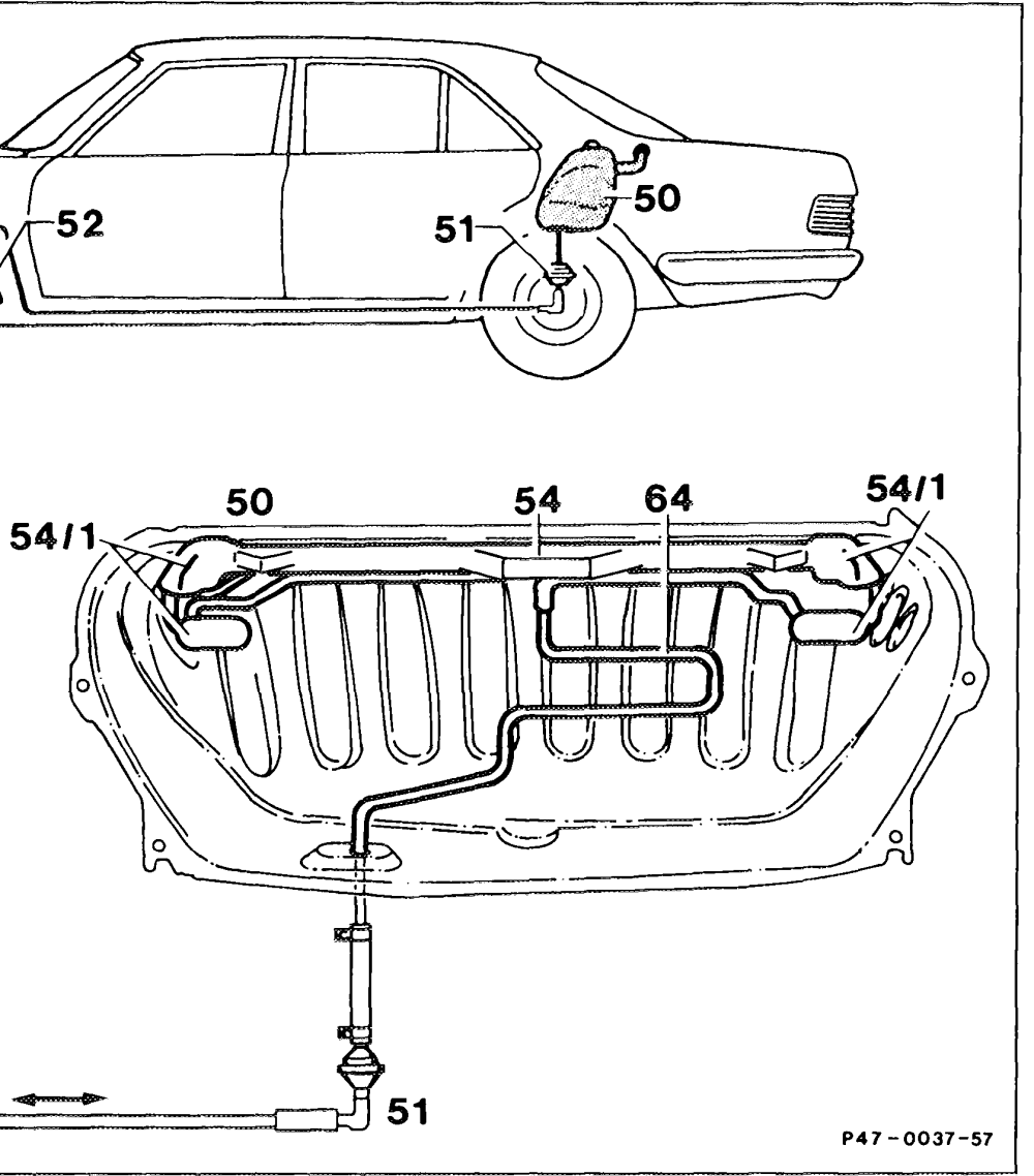
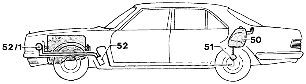
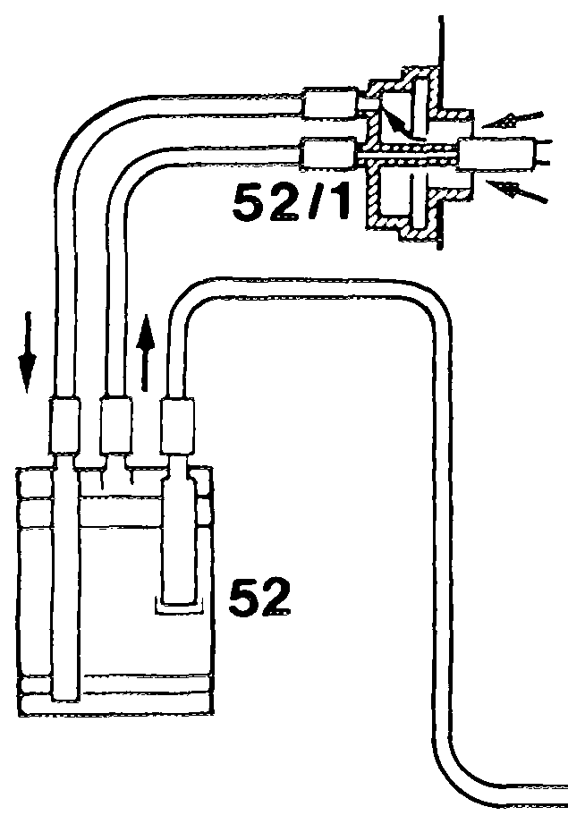
The ventilation system consists of a central pipe (54) with interrupter vessels (54/1). The interrupter vessels (54/1) prevent fuel escaping along the vent line (64). The vent line (64) runs from the central pipe to the vent valve (51). Air is admitted to, and released from the fuel tank (50) through the charcoal canister (52) and the boot (52/1).