Checking and adjusting camshaft timing
WIS 05-215
Timing in degree (°) crankshaft with 2 mm valve lift
Camshaft code number! ) Engine Engine Intake valve opens ATDC?) left/right special version No.
12° (10°) 02/03 117.960
20° (18°) 117.961
22° (20°) 012.468/01 116.964 116.965 117.962 117.963 117.964 117.965
18° (16°) 012.406/10 14/15 117.963
17° (16°) 16/17 117.968 012.480/01
27° (26°) 18/19 012.468/05 117.967 012.468/06 117.968 012.468/14 012.468/15
21° (20°) 20/21 116.965 117.965
17° (16°) 117.968 RUF 24/25
26/27 117.967 012.468/05 117.968 CAT 012.468/06 27° (26°) 012.468/14 012.468/15
12° (10°) 60/61 012.406/03 116.960 116.961 012.406/04 012.406/07 116.962 116.963 012.406/08
24° (22°) 116.960 012.406/01 62/63 012.406/02 116.961 116.962 012.406/05 116.963 012.406/06
16° (14°) 70/71 012.468/03 116.962 012.468/04 116.963 116.964 116.965
1) Camshaft code number association can be taken from the spare part microfilms. ) With new timing chains and a running time of below 20 000 km, adjust the timing of the right-hand camshaft according to the values in brackets.
F3
Bolts for cylinder head cover 3
| Bolts for camshaft sprockets M 14 x 1.5 x 40 | 100 |
| Hydraulic valve clearance compensating elements in cylinder head | 60 |
Special tools
Spring compressor for valve spring – 123 589 03 61 00
Dial gauge holder – 363 589 02 21 00
Valve clearance wrench 17 mm – 116 589 02 01 00
oan Socket insert 27 mm – 001 589 65 09 00
eoswnowe) Square drive – 617 589 00 16 00
Conventional tool
e.g. Mahr, D—7300 Esslingen Dial gauge A 1 DIN 878 Order No. 810
—*t t t t >
Note 0,0 0,0 0,0 0,0 et tf @f During assembly jobs it is sufficient if the marks on the camshafts coincide at ignition TDC position of SS 1st cylinder.
Check ,,intake valve opens” on 1st and 6th cylinder
515486372 at 2 mm valve lift.
Checking
SN
1 Check camshaft code number on rear end of camshafts.
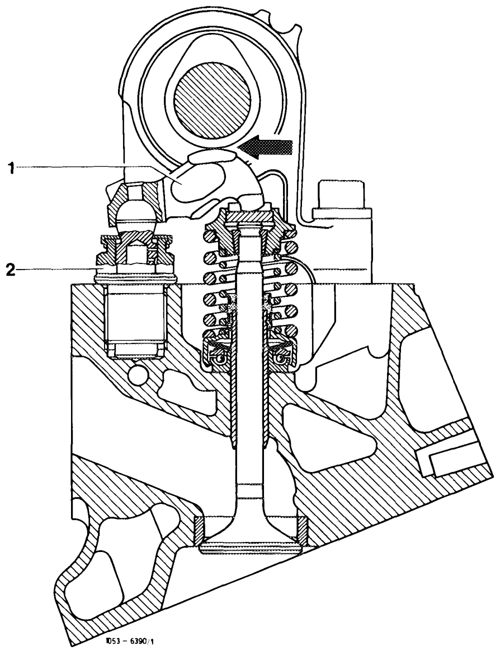
pensating elements (2) on intake valve of 1st and 6th cylinder. Install valve adjusting screw (1), part No. 116 050 11 20, on intake valve of Ist and 6th cylinder instead of compensating elements (2). Install rocker arm.
Caution! The rocker arms and the valve clearance compensating elements should be installed in the place from which they were removed.
3 Rotate crankshaft (27 mm socket) until the cam tip rests against intake valve of 1st cylinder in upward position.
Rotate crankshaft in engine direction of rotation only.
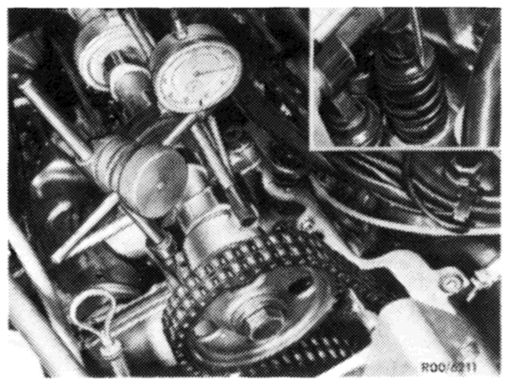
4 Turn valve adjusting screw until rocker arm rests free of play against camshaft heel (arrow).
5 Attach dial gauge holder to cylinder head.
6 Clamp dial gauge with extension pin in dial gauge holder with a preload of 3 mm.
The measuring pin should rest on the valve spring retainer in an accurately vertical position.
7 Set the large pointer to 0.
8 Rotate crankshaft until the pointers of the dial gauge return by 2 mm to a preload of 1 mm. The valve lift will then be 2 mm.
9 In this engine position the value on the vibration damper should be in agreement with the value ,, Intake valve opens” in the table.
10 Perform this test on the intake valve of 6th cylinder by repeating figures 4 to 9.
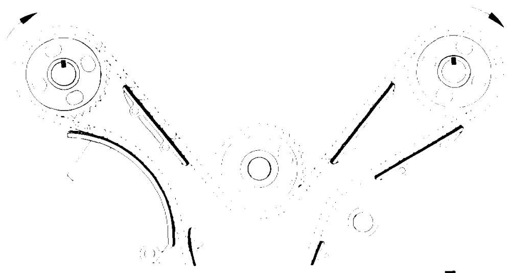
If the timing must be corrected, install an offset Woodruff key or if the chain has been elongated too much, a new timing chain.
Woodruff keys are available in the following steps:
Offset Part No. Fora mm correction of approx. A ( +
0.7 621 991 04 67 4° crank angle oa ware
0.9 621 991 0267 6 1/2° crank angle r v
1.1 621 991 01 67 8° crank angle Letts : 1.3 621 991 00 67 10° crank angle Co 8 fps.
An offset by one tooth on the camshaft sprocket results in approx. 18° on the crankshaft. Installation position A results in earlier commencement of An offset of the Woodruff key to the right (in the opening
: . wo . : Installation position B results in later commencement of
direction of driving) results in an earlier commence- opening ment of opening, while an offset to the left results in a later commencement of opening.
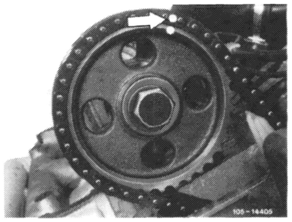
11. Mark camshaft sprockets and timing chain relative to each other (arrow).
12 Remove the respective camshaft sprocket.
13 Place a rag under the camshaft and remove the Woodruff key.
14 Insert the selected Woodruff key.
15 Install the camshaft sprocket while paying attention to the color coding.
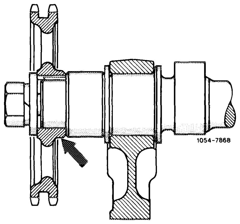
The wide collar on the camshaft sprocket should face to the camshaft (arrow).
Do not tighten the bolt.
16 Repeat items 4 to 9.
17 Tighten bolt to 100 Nm.
18 Check basic position of hydraulic valve clearance compensating elements and correct (05-213).
19 Complete the engine.