Installation and centering of intermediate flange
WIS 01-220
Engine 117.960 with automatic transmission 722.006 up to engine end No. 001685
Data
Permissible radia) runout deviation at the fitted collar 0.10 of the intermediate flange with a full turn
Permissible lateral runout deviation on the fitted collar 0.10 of the intermediate flange with a full turn
Fitted hole in the intermediate flange for centering dowels 12.016 to 12.043
Tightening torques Nm
Mounting bolts for intermediate flange 50
Mounting bolts M 8 for support angle 30 on crankcase
Mounting bolts M 10 for support angle 50 on intermediate flange
Pre-torque 40 Necked-down bolt for driven plate 90–100° Torque angle
Special tools
8 2 Dial gauge holder a i (2 required) – 363 589 02 21 00
Socket insert 27 mm, 1/2’ drive for “8 rotating the engine – 001 589 65 09 00
1/2” square drive insert, 80 mm long for rotating the engine ca – 617 589 00 16 00
Tool for self-fabrication
Threaded pin see Fig. No. 3
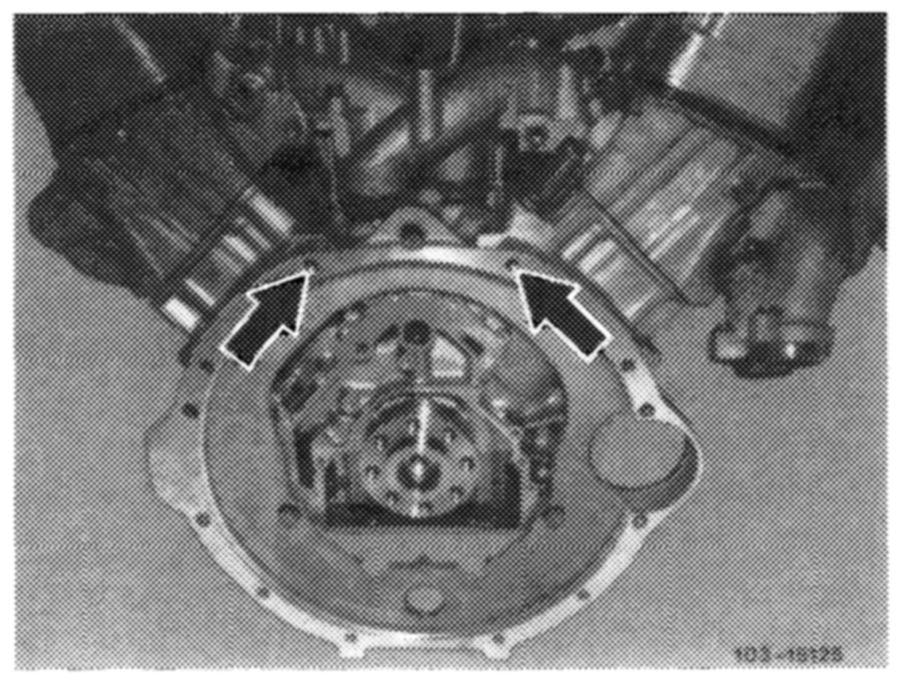
|f an intermediate flange is renewed it has to be centered.
Intermediate flange and support angle are only installed in model 107.026 with engine 117.960 in combination with the automatic transmission 722.006 up to chassis end No. 001627, and engine end No. 001685 respectively. The hole pattern to mount the transmission is not identical with that of the cast-iron engines. The two mounting threads in the crankcase (arrows) have each been moved 9 mm further inside.
Installation and centering
1 Fit the intermediate flange onto the dowel pins (arrows) on the crankcase. Remove support angle.
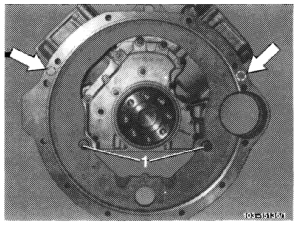
2 Lightly tighten the two mounting bolts (1).
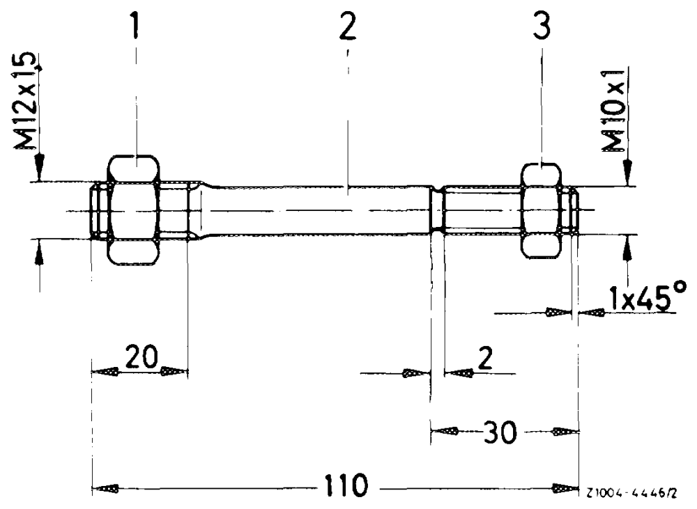
3 Screw threaded pin into the crankshaft and lock.
1 Hexagon nut M 12 x 1.5 2 Threaded pin 10 mm dia. 3 Hexagon nut M 10 x 1
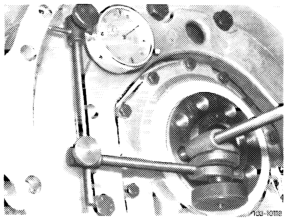
4 Attach dial gauge holder with dial gauge to threaded pin.
5 Position measuring pin on the fitted round centering surface of the intermediate flange to measure radial and lateral runout. Set dial gauge to 0.
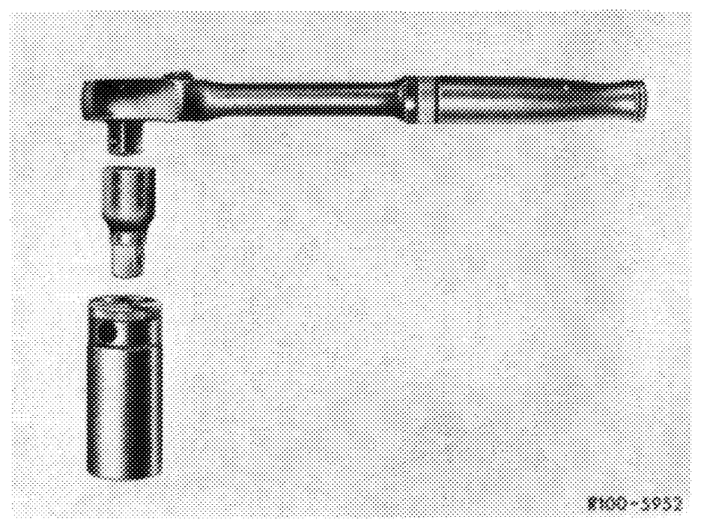
6 Turn crankshaft in direction of rotation a full turn using the tool combination. Maximum lateral and radial runout is 0.10 mm. In other words, the total deflection of the pointer may not exceed 0.10 mm. If lateral runout is greater than 0.10 mm, renew intermediate flange.
Note: When turning the crankshaft, ensure that the measuring pin of the dial gauge is not sticking.
7 Correct the radial runout with light taps on the intermediate flange.
8 Tighten mounting bolts.
Note: If the radial runout is greater than 0.10 mm, remove intermediate flange.
9 Drill both fitted holes in the intermediate flange to 12.1 mm.
10 Repeat figures 1—8.
11 Mount supporting angle only after the intermediate flange has been attached to the crankcase.
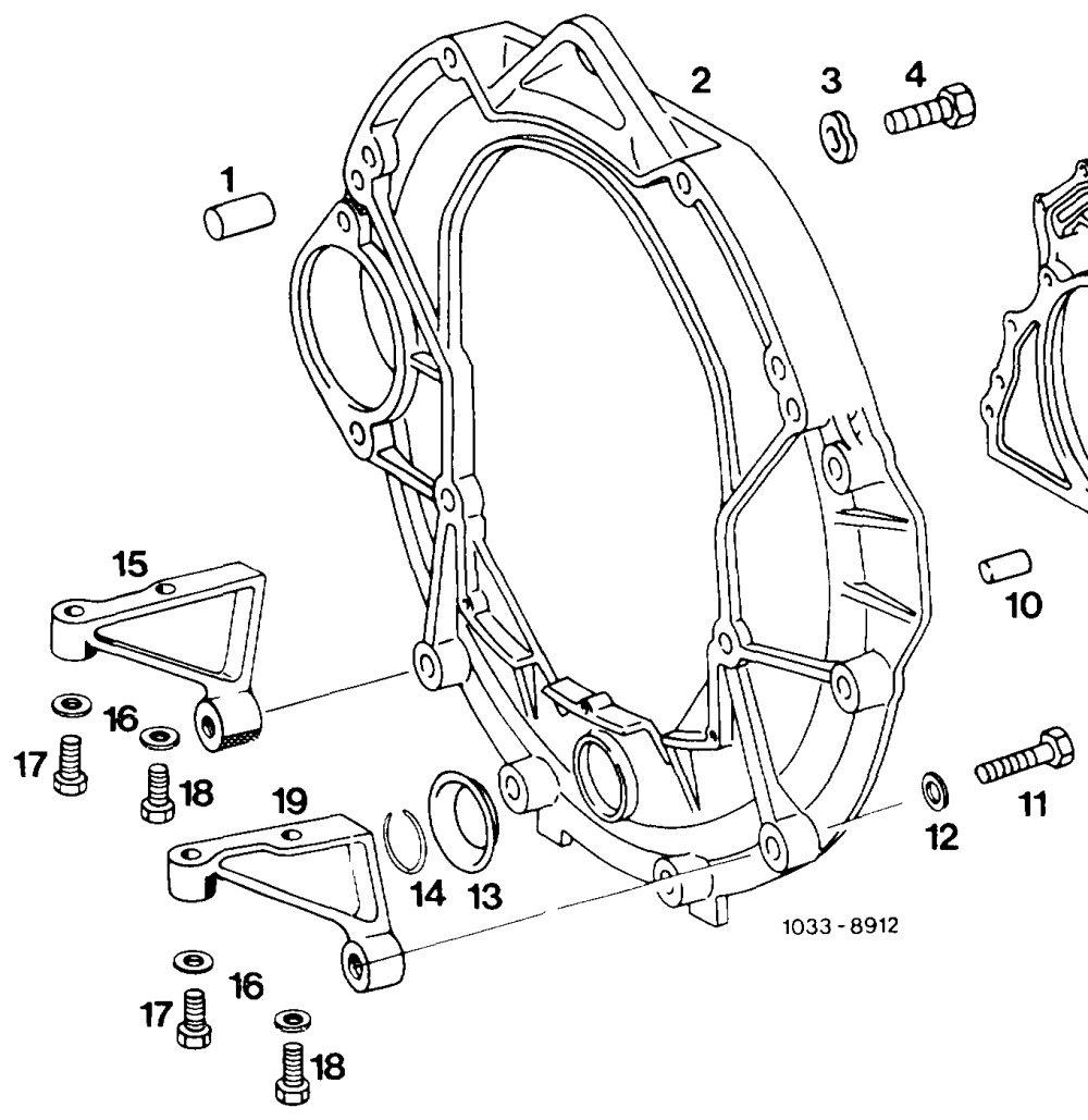
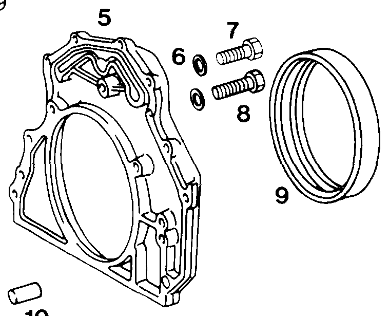
Model 107.026 with engine 117.960 and transmission 722.006 (W 3 B 050)
1 Dowel pin 12 x 22 mm, 2 required 7 Bolts M 6 x 25, 9 required 13 Cover Repair dowel pin dia. 12.2 x 22 mm 8 Bolts M 6 x 20, 4 required 14 Circlip 38 Intermediate flange up to Radial sealing ring 13 mm wide, Onhw Nn 9 15 Support angle right engine end No. 001685 repair radial sealing ring Washer A 8, 4, 4 required 16 Spring washer B 10, 2 required 10.5 mm wide Bolt M8 x 40 17 Dowel pin 6 h8 x 10, 2 required Bolt M 10 x 35, 2 required 10 18 Bolt M 8 x 65, 2 required 11 Bolt End cover 19 Support angle left 12 Washer Washer A 6, 4, 13 required
F3