Removal and installation of coolant thermostat
WIS 20-110
Coolant pump, coolant thermostat, inlet connection
Engines 116.960 and 116.961 standard version, 117.960 and 117.961
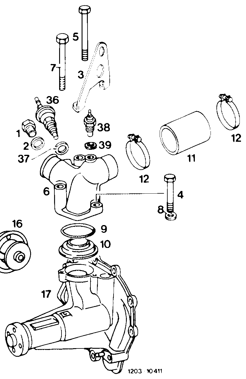
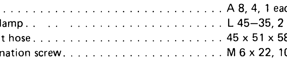
1 Closingplug………… 0.000.200 eee M 14 x 1.5, vehicles without air conditioner and automatic climate control Sealingring. 2.0… ee ee A 14x 18 — Cu Suspension eye Hex. head bolt M 8 x 30, 25 Nm M8 x 65, 25 Nm Hex. head bolt Inlet connection M 8 x 85, 25 Nm Hex. head bolt A8, 4, 1 each Washer Check, renew if required Sealing ring Spacer ring . 42 x 51x 40 Coolant hose Hoseclamp……….. 0.0.00 0c eee eee L 45-35, 2 each Combination screw… 0.0.0… 00 eee eee M6 x 20, 3 each, 10 Nm Coolant thermostat cover Sealing ring Check, renew if required
+ Start of control 75 °C, end of control (fully opened) Coolant thermostat
max. 92 °C. Ensure correct installation Position 7 Coolant pump +2 On: 110 3 °c, Off: 105 + 3 °C. Switches second stage 36 Temperature switch
supplementary fan on vehicles with air conditioner or automatic climate control 37 Sealing ring A 14x 18 — Cu 38 Temperature transmitter For coolant temperature indicator in instrument cluster Installed in right-hand cylinder head up to the end of November 1980
39 Sealingring…… 2… 0… eee eee eee Sealing ring A 14x 18 — Cu
Engines 116.960 and 116.961 national versions @5) C2) CS) Gs) 1981
Engines 116.962, 116.963, 117.962 and 117.963
10
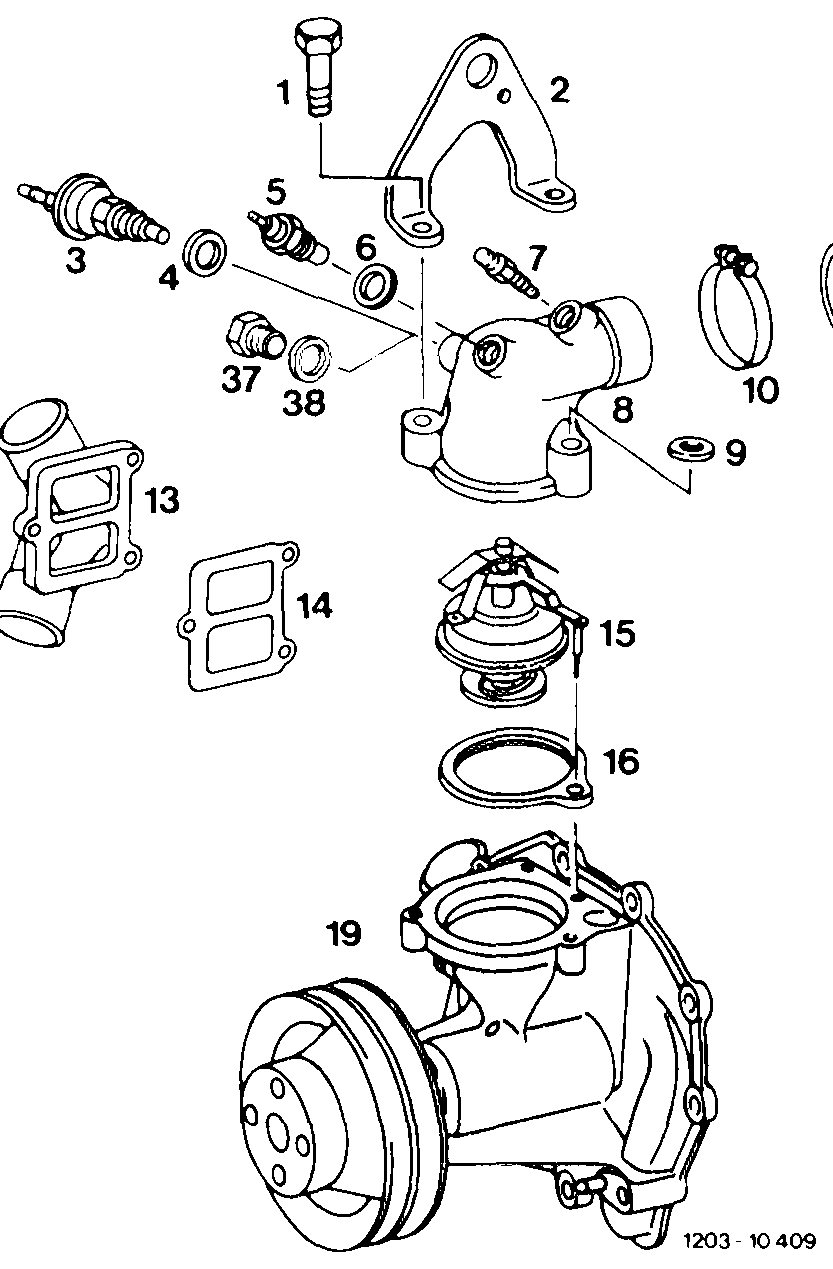
M 8 x 35, 3 each, 25 Nm
1 Hex. head bolt 0.0.20. eee
2 Suspension eye
3 Temperature switch 0.0.0.0… 0.000000 For second stage supplementary fan on vehicles with air conditioner or automatic climate control 2c, Off: 105 + 3 °C 100 °C On: 1107
A 14x 18 — DIN 7603 — AL Sealing ring NOs Temperature transmitter… …………00. For coolant temperature indicator in instrument cluster
A 14x 18 — DIN 7603 — AL
Sealing ring Only engines 116.960 and 116.961 national versions Vent screw @3 GD GS) Gd 1981 to August 1981
8 Inlet connection
9 Washer each
10 Hoseclamp.. 11 Nm
12 Combination
13 Cover
14 Gasket Renew Start of control 84 + 2 °C, end of control (fully opened)
15 Coolant thermostat ………….0 0000005 max. 99 °C, no vent valve, observe installation instructions
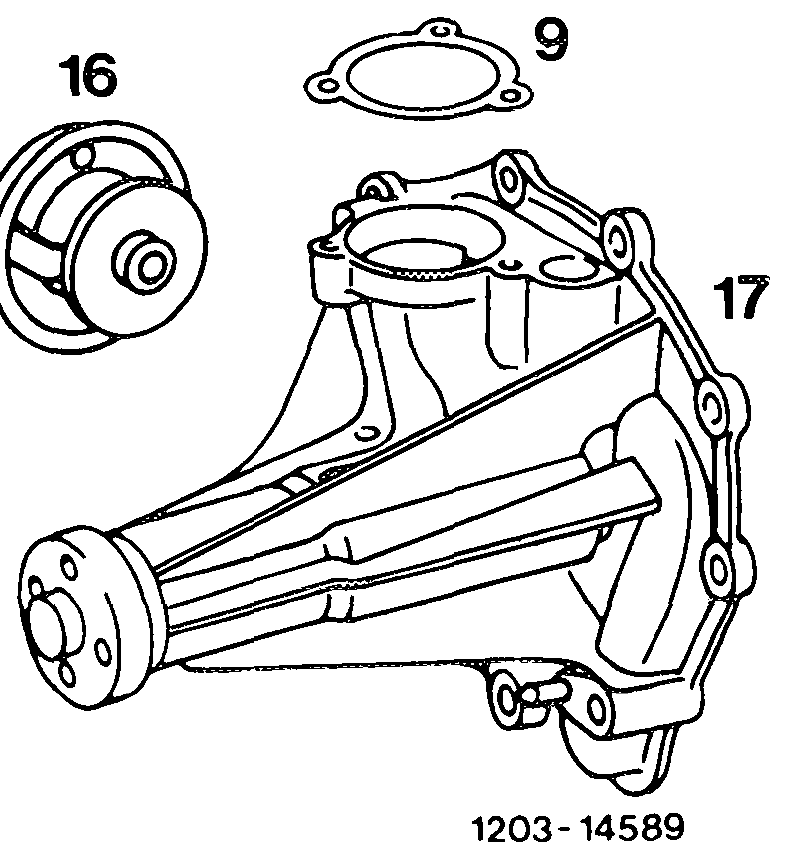
16 Gasket Check, renew if required
19 Coolant pump
37 Closing plug 0.0.0.0 eee eee eee M 14 x 1.5 AL alloy, vehicles without air conditioner or automatic climate control A 14x 18 — DIN 7603 — AL
38 Sealing ring
F3
inlet connection
Engines 116.964/965 standard version
117.964/965/967/968
12
Ti
13 @ 4 = @&8
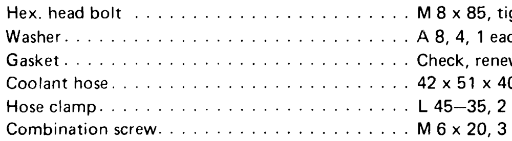
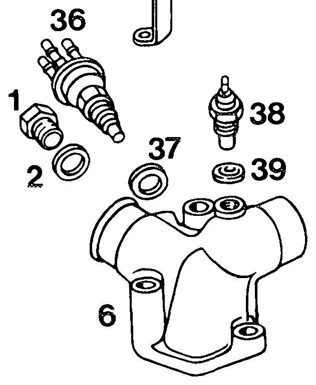
Closing plug 0… eee ee es M 14 x 1.5, vehicles without air conditioner or automatic climate control Sealingring 6.20… 0.2. eee A 14x 18 — DIN 7603 — AL Suspension eye Hex. head bolt …………0. 00.000 0000, M 8 x 30, tightening torque 25 Nm Hex. head bolt 0.020.000 0000, M 8 x 65, tightening torque 25 Nm Inlet connection tightening torque 25 Nm
if required
each each, tightening torque 10 Nm Cover coolant thermostat Sealingring.. 6–6… eee eee Check, renew if required +2 Coolant thermostat …….0…….–,-4. Start of control 80 2 °C, end of control (fully opened) max. 94 °C. Ensure correct installation Position . +2 Temperature switch. ……………00005 On: 110 3 °c, Off: 105 + 3 °C. Switches second stage 36
supplementary fan on vehicles with air conditioner or automatic climate control Sealingring.. 2… cee ee eee A 14x 18 — DIN 7603 — AL 37 38 Temperature transmitter… 0.000005 For coolant temperature indication in instrument cluster Installed in the right-hand cylinder head up to the end of 1980 Sealingring… 0.2… eee eee A 14x 18 — DIN 7603 — AL 39
Tightening torques
Cover coolant Engines 116.960 and 116.961 thermostat standard version 117.960, 117.961 Fastening screws Inlet connection Engines 116.960 and 116.961 national versions @us) Ca) ce Gs) 1981 25 116.962, 116.963, 117.962, 117.963
Model 107 Drain plug radiator 1.5–2!) Model 126
’) This torque can be generated with a washer or coin.
Special tools
Tester for cooling system – 001 589 48 21 00
(„11004-8325
eo Radiator cap with hose for tester q – 605 589 00 25 00
Conventional tool
7 mm socket insert on flexible shaft e.g. Hazet, D—5630 Remscheid Order No. 426–7 for hose clamps with worm drive
Note For a more accurate indication of coolant temperature, the temperature transmitter has been moved from right-hand cylinder head into the inlet connection above the coolant pump.
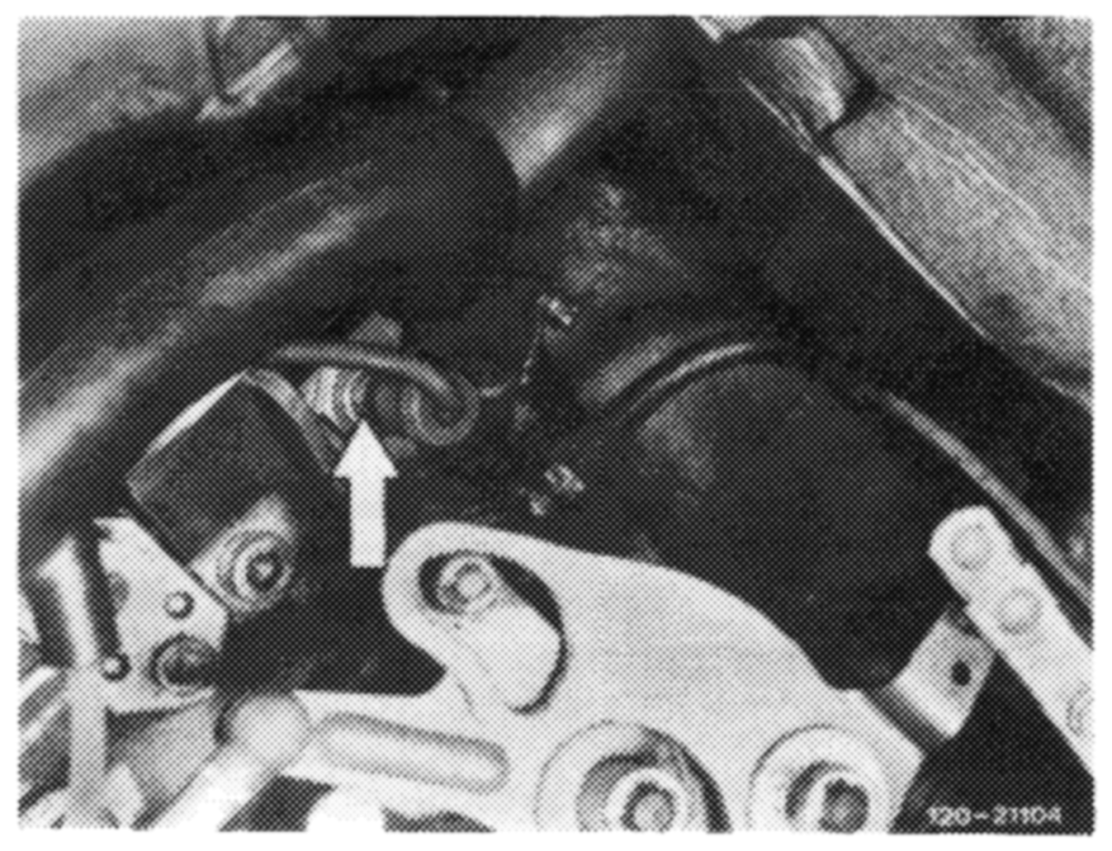
Subsequent conversion on older vehicles is possible. For this purpose, install inlet connection 117 201 12 30. The existing electrical line from the temperature sensor to the coolant temperature indication in the instrument cluster can be used without change.
Previous installation position temperature transmitter (arrow)
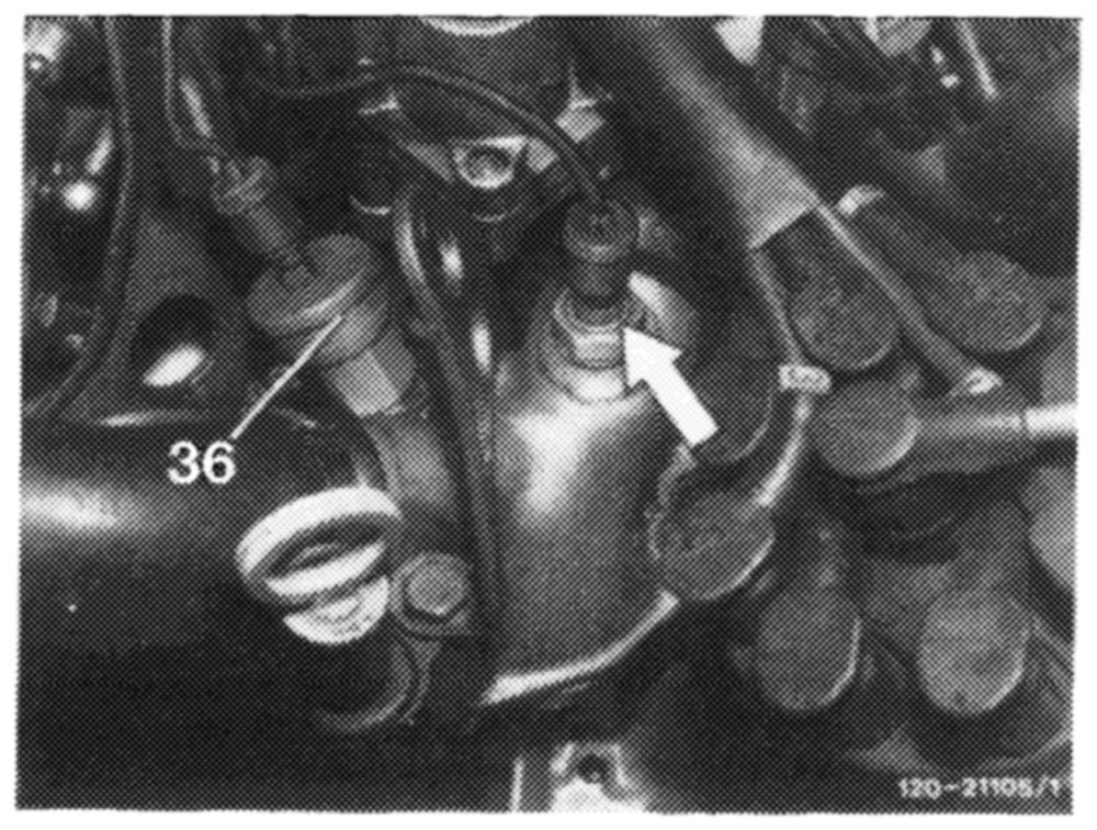
Current installation position temperature transmitter (arrow)
Removal
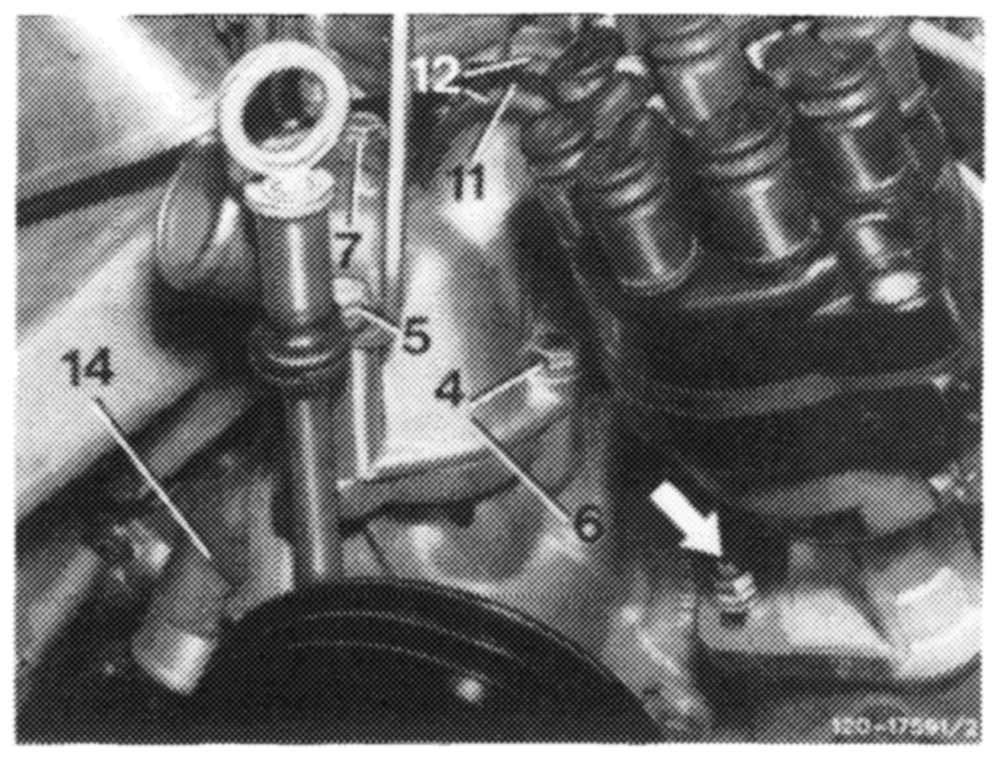
1 Drain coolant (20-010).
Engines 116.960, 116.961 standard version,
116.964, 116.965, 117.960, 117.961, 117.964, 117.965, 117.967 and 117.968
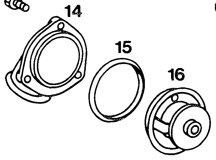
2 Disconnect coolant hose from cover (14).
3 Remove cover (14) and coolant thermostat.
Engines 116.960 and 116.961 national versions
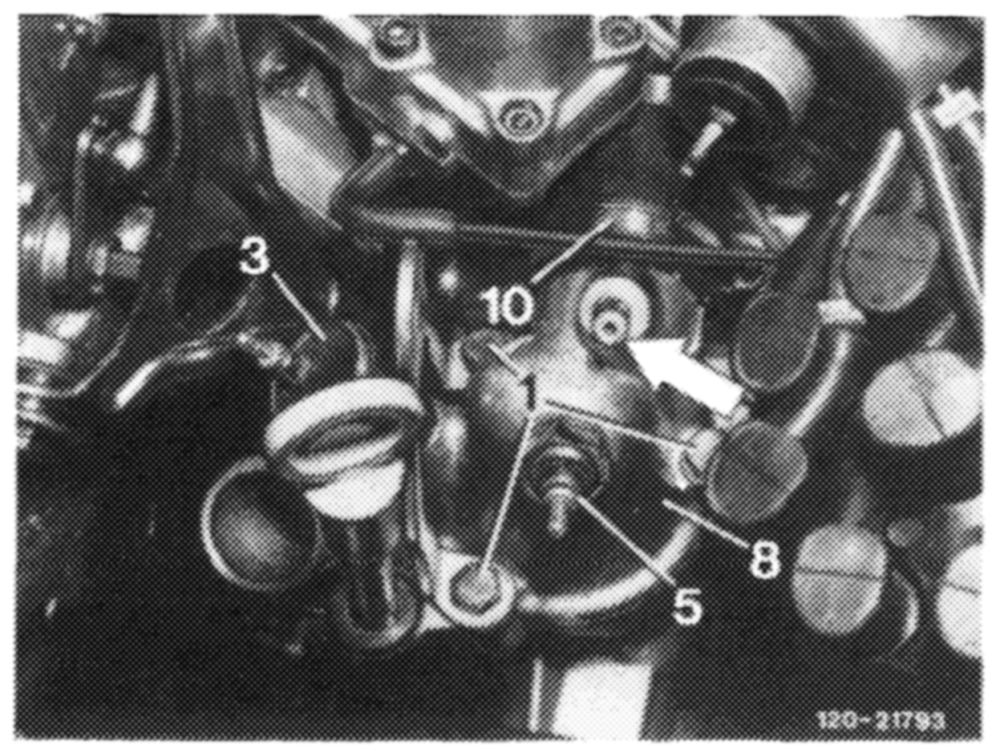
@ D © @i981 116.962, 116.963, 117.962, 117.963
4 Pull off single plug of electric lines on temperature switch (3) and on temperature transmitter (5).
5 Disconnect vent hose on connecting pipe (arrow). (Not required on engines 116.960 and 116.961 GS G CS) Gd 1981 to August 1981).
6 Loosen hose clamp (10), unscrew fastening screws (1) and remove inlet connection (8) together with coolant thermostat.
Installation
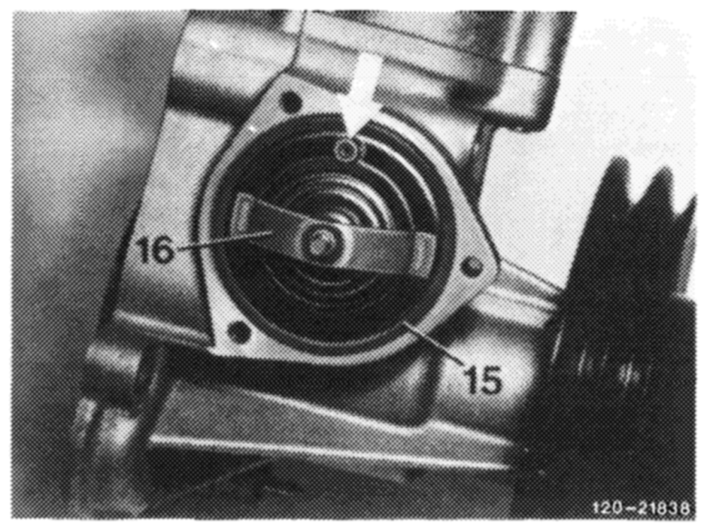
Engines 116.960, 116.961 standard version,
116.964, 116.965, 117.960, 117.961, 117.964, 117.965, 117.967 and 117.968
7 If required, install coolant thermostat (16) with a new sealing ring (15) in such a manner that the ball valve is on the top (arrow). During installation, ensure free movement of the ball in the valve.
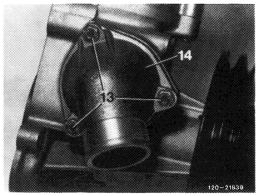
8 Install cover (14) and tighten fastening screws (13) to 10 Nm.
Engines 116.960 and 116.961 national versions
@) @ CG) Gd 1981 116.962, 116.963, 117.962, 117.963
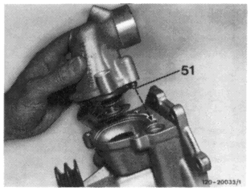
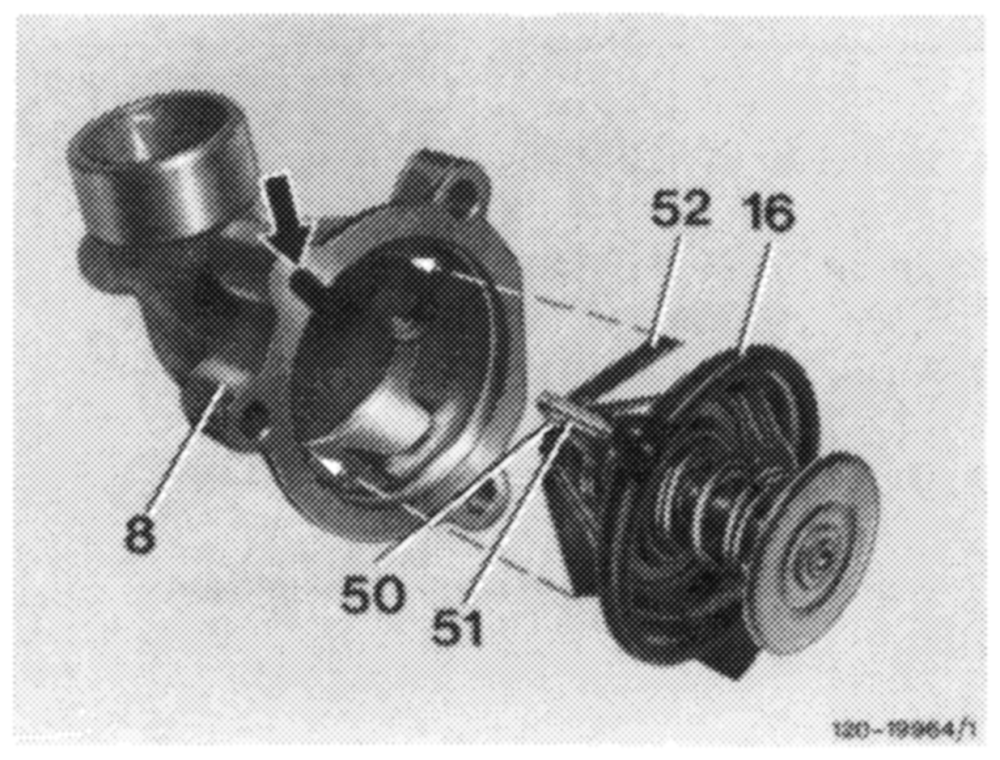
9 If required, fit new gasket (16) to coolant thermostat. Install coolant thermostat in inlet connection (8) in such a way that the lever (50) engages with pin (51) in the recess (arrow) and that the two ends of the spring (52) engage in the retaining lugs (dashed arrows).
10 Install inlet connection with installed coolant thermostat in such a manner that the pin (51) engages in the control bore in the cooling pump housing (dashed arrow).
Tighten fastening screws for inlet connection to
25 Nm.
11. Refit single plug of electric lines to temperature switch and temperature transmitter and connect vent hose.
12 Fill in coolant (20—010).
13 Check cooling system for leaks by pressuretesting with tester (1 bar gauge pressure).