Coolant circuit and engine cooling
WIS 20-005
Coolant circuit
Engines 116.960 and 116.961 standard version
Engines 117.960 and 117.961
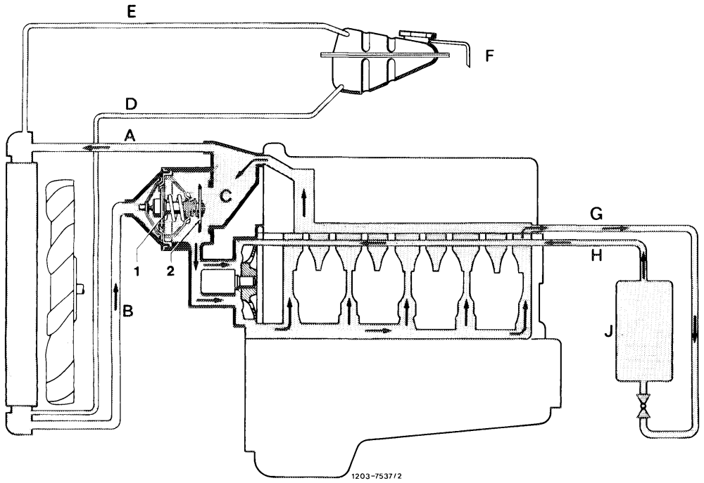
A From engine to radiator G_ Heating water feed from cylinder head (intake manifold B From radiator to coolant thermostat left) to heat exchanger C Bypass duct H_ Heating water return flow duct in cylinder crankcase D Coolant flow from expansion tank to radiator right E Vent line J Heat exchanger F Overflow hose 1 Main valve coolant thermostat 2 Bypass valve coolant thermostat
Warming-up period (coolant temperature up to
approx. 75 °C)
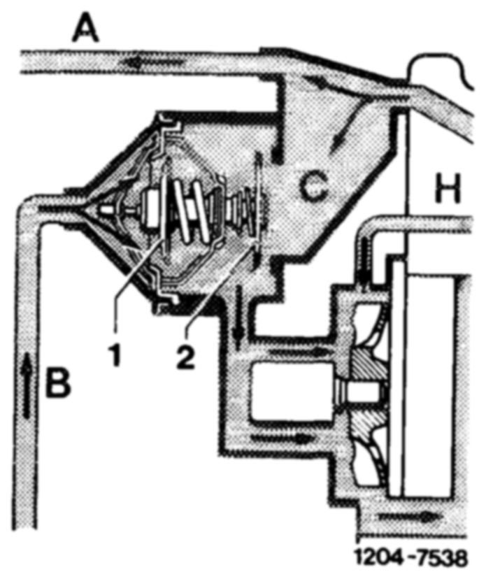
The main valve (1) is closed up to a coolant temperature of approx. 75 °c and the bypass valve (2) is fully opened. Flow (B) from the radiator is interrupted and the coolant flows through the bypass duct (C) directly to the coolant pump.
Part-load operation (coolant temperature approx.
75 °C to max. 92 °C)
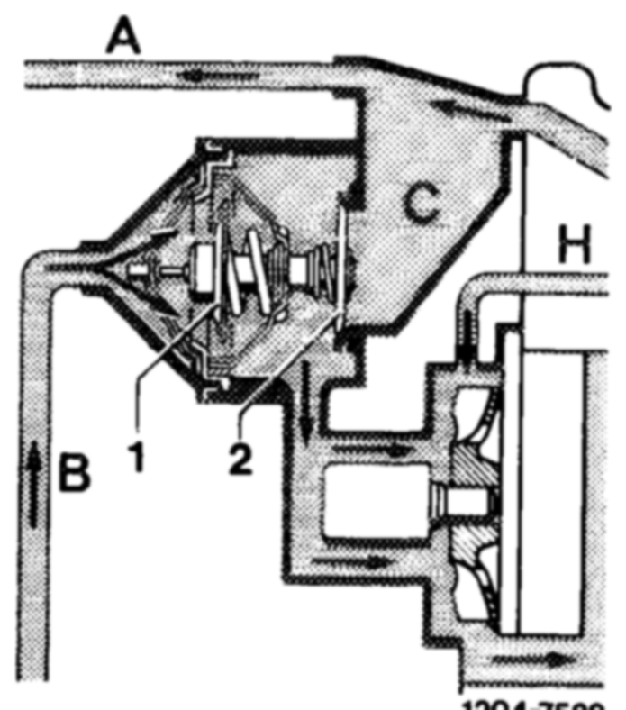
In the part-load range (engine at operating temperature), the main valve (1) as well as the bypass valve (2) are more or less open depending on engine load and outside temperature. The coolant is directed as a function of coolant thermostat position both via the radiator (A and B) and the bypass duct (C).
Full load operation — High outside temperatures
(coolant temperature above 92 °C)
Main valve (1) is fully open. Bypass valve (2) closed.
Under severe engine load and high ambient temperatures, the bypass duct (C) is closed not later than at a coolant temperature of 92 °C. The entire coolant must flow through the radiator. It is therefore wrong to remove the thermostat for an ,,improved”’ cooling of the engine.
20.7—-005/2. F3
Engines 116.960 and 116.961 national versions @S) G) CS) @sa 1981
Engines 116.962, 116.963, 117.962 and 117.963
H
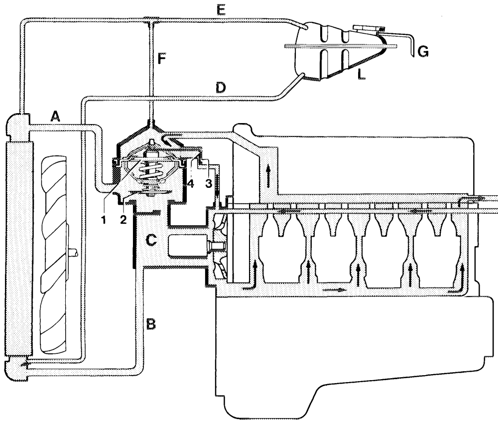
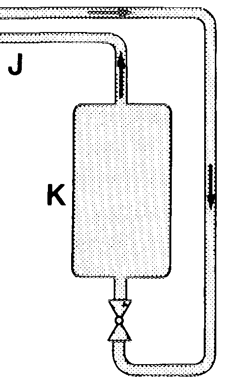
A From coolant thermostat to radiator K_ Heat exchanger B From radiator to coolant pump L Expansion tank C Bypass duct D Coolant flow from expansion tank to radiator 1 Main valve coolant thermostat E Vent hose upper coolant box to expansion tank 2 Bypass valve coolant thermostat F Vent hose inlet connection (thermostat housing) to vent 3 Control bore hose between upper coolant box and expansion tank 4 Pin mio Overflow hose Heating water feed from cylinder head (intake manifold left) to heat exchanger a Heating water return duct in cylinder crankcase right
Note
| On the engines 116.960 and 116.961 national versions | tional versio | |
| @s) >) S @s®) 1981, the vent line (F) is installed | F) is installe | |
| with effect from August 1981. | Be | |
| Production breakpoint: August 1981 | Be | |
| Model Engine | Engine end No. | Chassis end No. |
107.025 003752 107.045 116.960 012479 008644 126.032 126.033 116.961 019965 019854
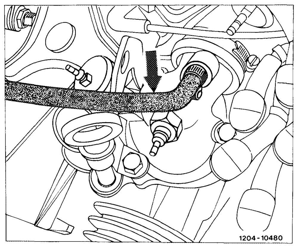
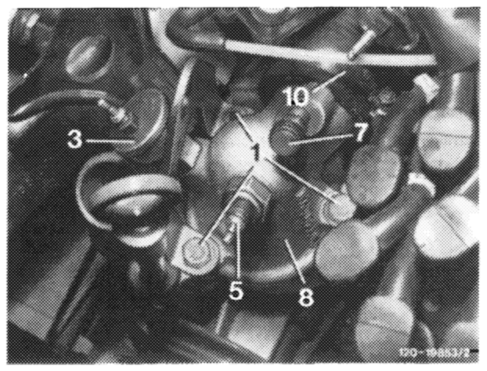
cooling system has been continuously and automatically vented during filling operation and also during operation of engine, the vent screw (7) has been used up to August 1981. This screw must be opened for venting when filling the cooling system. When using this vent screw, no automatic, continuous venting of cooling system will occur.
Operation
Note: Independent of coolant temperature or position of coolant thermostat, a small quantity of coolant will always flow through the control bore (3) to the coolant pump. The pin (4), connected to the wax element by means of a web, will move up and down with the stroke of the wax element in the control bore to keep the bore free of contamination.
Warming-up period (phase 1, coolant temperature
up to approx. 84 °C)
The main valve (1) is closed up to a coolant temperature of approx. 84 °C and interrupts the coolant flow towards the radiator (A) and through the bypass duct (C). Only a small quantity of coolant will flow through the control bore (3) to the coolant pump during the warming-up period. This design provides faster heating of the engine during the warming-up period, especially in the combustion chamber region in the cylinder head.
Part-load operation (phase 2, coolant temperature
approx. 84 °C to max. 99 °C)
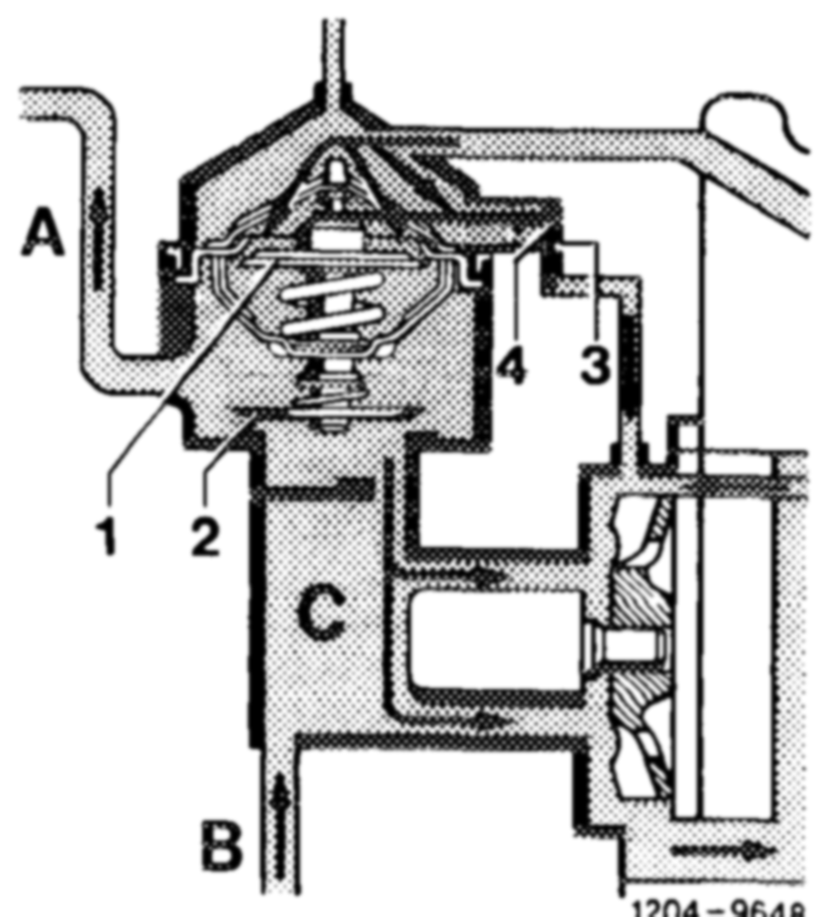
In the part-load range (engine at operating temperature) the main valve (1) and the bypass valve (2) are more or less open depending on the engine load and ambient temperatures. The coolant flows as a function of coolant thermostat position both through radiator (A and B) as well as bypass duct (C) to the coolant pump.
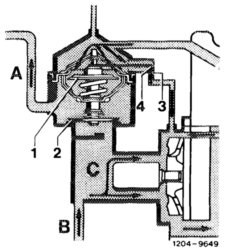
Under heavy engine load and/or high ambient temperatures the main valve (1) is fully open at a coolant temperature of approx. 99 °C, and the bypass valve (2) is closed. The entire coolant will now flow through the radiator to coolant pump (A and B). It is therefore wrong to remove the coolant thermostat to obtain an ,,improved”’ engine cooling.
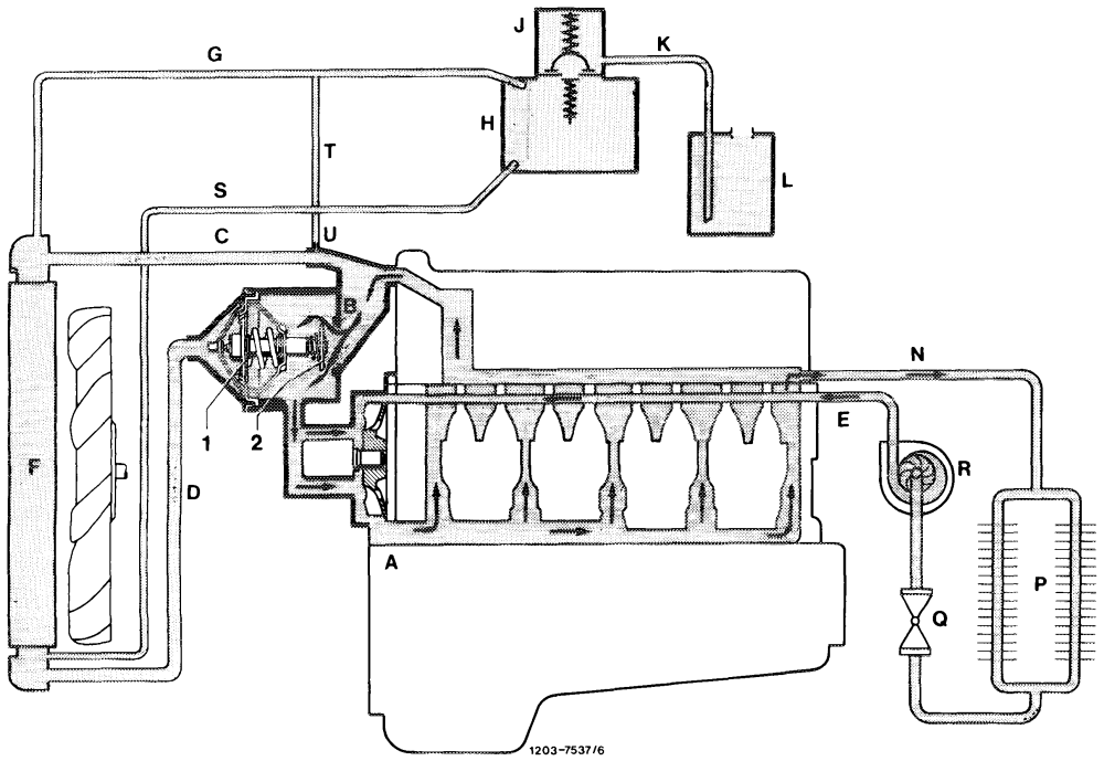
Coolant circuit (3-phase)
A From the coolant pump to the crankcase L Overflow tank (only with air conditioner/automatic B From the cylinder head to the inlet pipe and bypass duct climate control) C From the inlet pipe to the radiator N_ From cylinder head/intake manifold to heat exchanger D From the radiator to the thermostat P Heat exchanger E From the circulation pump to the coolant pump Q Mono valve F Radiator R_ Circulation pump electric G Vent hose from radiator to expansion tank S Coolant filling hose H Expansion tank (in bypass circuit) with coolant level T Vent hose from inlet pipe indication U Vent valve J Plug with pressure relief and vacuum valve 1 Main valve coolant thermostat 80 °C K Overflow hose 2 Bypass valve
Coolant pump
with laterally arranged thermostat 80 °C in the coolant feed from the radiator:
Operation
Coolant temperature up to approx. 80 °C
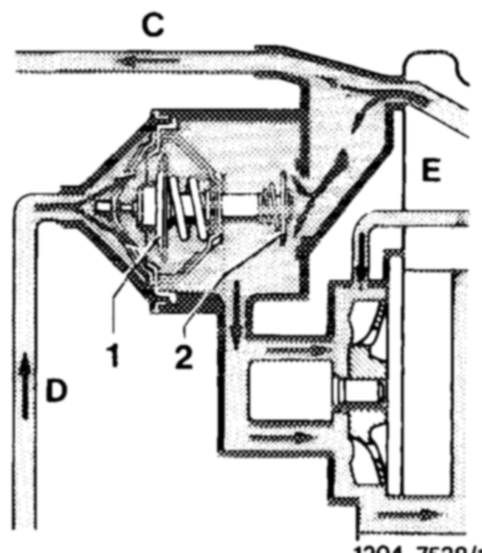
The main valve (1) is closed and the bypass valve (2) fully open. The feed (D) from the radiator is interrupted and the coolant flows via the bypass duct (B) directly via the coolant pump to the crankcase.
Coolant temperature of approx. 80 °C up to max. 95 °c
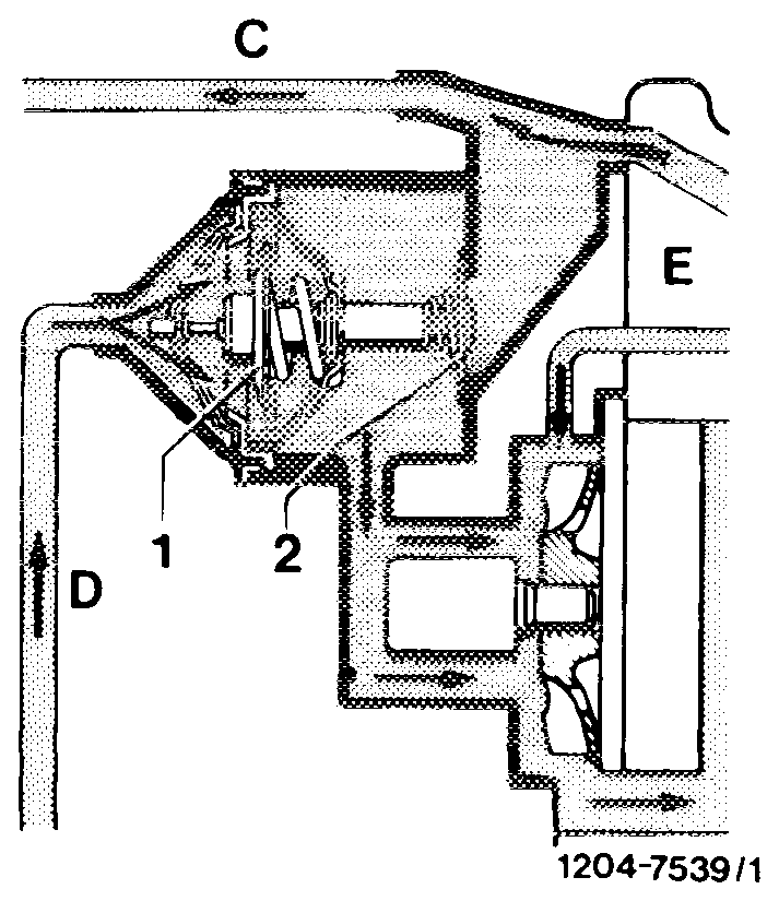
In the part-load range (engine at operating temperature) the main valve (1) and the bypass valve (2) are more or less open depending on the engine load and ambient temperature. The coolant is directed via both the radiator (C and D) and also the bypass duct as a function of the thermostat position.
Coolant temperature above 95 °c
The main valve (1) is fully open and the bypass valve (2) is closed.
With heavy engine load and high ambient temperatures, the bypass duct is closed by the bypass valve (2) not later than at a coolant temperature of 95 °C. The entire coolant must flow through the radiator (C—D). It is therefore wrong to remove the thermostat for an ,,improved”’ cooling of the engine.
Expansion and overflow tank
Production breakpoint: September 1984
Only for vehicles with air conditioner or automatic climate control.
The drain hose at the filler neck of the expansion tank leads to the overflow tank. The overflow tank collects the coolant forced out through the overflow hose at high ambient temperatures after the engine has been switched off.
After the coolant has cooled down, the coolant in the overflow tank returns to the expansion tank due to the vacuum created in the cooling system.
Coolant loss is largely eliminated in this way.
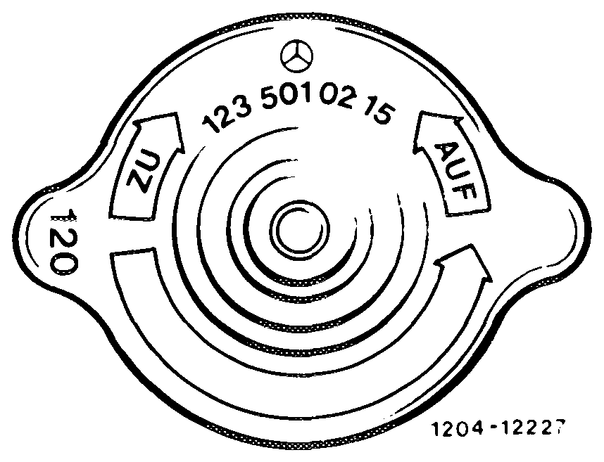
In order to prevent wrong air being drawn in at the expansion tank cap with vacuum in the cooling system, the cap (1.2 bar) was provided with a rubber seal. Only this cap, part No. 123 501 02 15, may be used.
Note on repairs
From the installation of the coolant level transmitter the expansion tank has been reinforced and can be used in place of the previous expansion tank together with a plug with gasket and locking ring.
Coolant level indication
The dynamic coolant level indication monitors the coolant level in the expansion tank with running engine.
Components
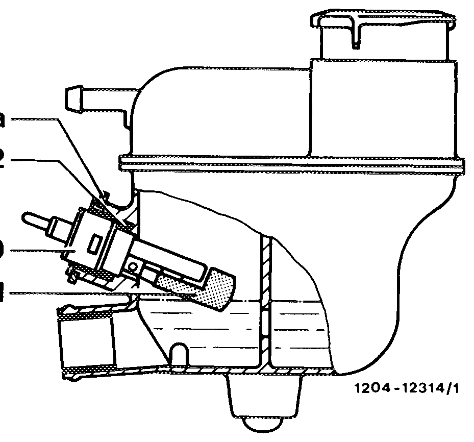
Coolant level transmitter (550) in the expansion tank Control lamp in instrument cluster. Symbol: symbolic radiator.
550a 552
550 551
550 Coolant level transmitter 550a Locking ring 551 Float 552 O-ring
Operation
With the ignition switched on (key position 2) the control lamp lights up dimly and goes out with running engine (function control of bulb).
The coolant level in the expansion tank is explored by a float with permanent magnet (551) attached to the coolant level transmitter.
As from a certain coolant level the contact is closed and the control lamp lights up.
Depending on the driving style, the control lamp will first light up for a short time and later on permanently. If the control lamp lights up, fill up coolant. Electrical circuit diagram see Group 54.
Note on repairs
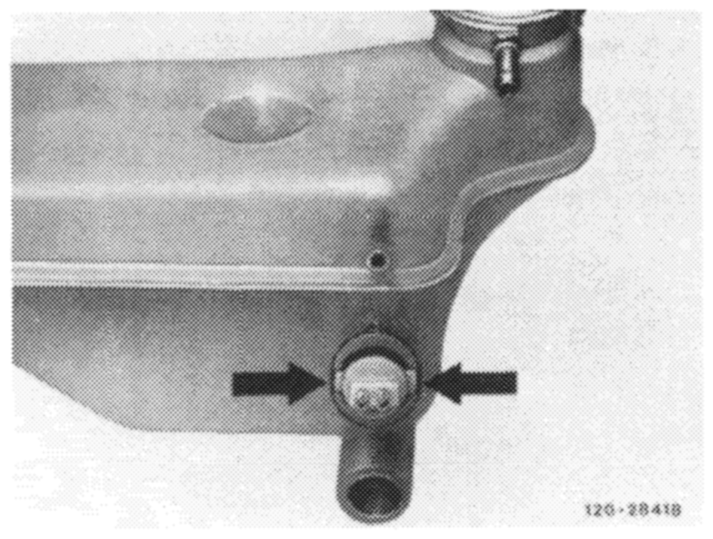
In order to avoid wrong installation of the coolant level transmitter, it is provided with two lugs of different widths, which engage in corresponding slots in the expansion tank (arrows).
It is pressed into the expansion tank and sealed with an O-ring (552). To remove the coolant level transmitter, remove locking ring.
Engine cooling
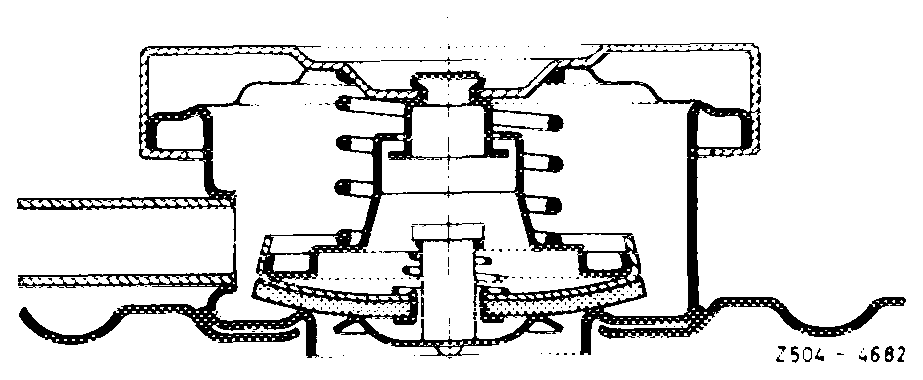
The spring-loaded cap (code number 120) serves to establish a gauge pressure of approx. 1.2 bar in the cooling system.
Renew coolant every 3 years.
Use only approved corrosion protection/antifreeze agents (see Service Product Specifications sheet 325.1).
Use only the Mercedes-Benz corrosion protection/ antifreeze agent, part No. 000 989 08 25.
For reasons of corrosion protection, the corrosion protection/antifreeze agent must be filled in under all operating conditions — even in tropical countries.
The water should be mixed with 40–45 % by volume of corrosion protection/antifreeze agent (corresponding to antifreeze protection up to —30 °c). A higher concentration is only practical with even lower ambient temperatures. Even at extremely low ambient temperatures not more than 55 % by volume of corrosion protection/antifreeze agent should be used (corresponding to antifreeze protection up to —45 °c), as the maximum antifreeze protection has been reached and an even greater percentage of corrosion protection/antifreeze agent will reduce the antifreeze protection and result in poorer heat dissipation.
Use clean and not too hard water. Potable water frequently meets the requirements. More accurate specifications can be taken from the Specifications on Service Products sheet 310.
Caution! Do not use any additives as these are not approved for use in passenger car engines. They do not increase the boiling point and offer no antifreeze protection. In addition, the necessary corrosion and cavitation protection is only partly obtained.
Draining and filling in coolant, see repair instructions on microfilms (20–010).
When driving under full load, on mountain roads and bumper to bumper, or following a fast ride on an express highway with subsequent traffic congestions, or when driving in areas with high outside temperatures, the coolant temperature indicator may rise up to the red mark if an antifreeze of at least —30 °C is filled in, without causing any ejection of coolant or faulty running of the engine.
When the engine is operated for an extended period with the vehicle stopped, e.g. during a congestion, it will be of advantage to move the selector lever of the automatic transmission into ,,N“’ position. This will reduce the heat developed in the transmission and consequently the additional heating-up of coolant by way of the transmission oil cooler.
When coolant is lost through leaks in the cooling system or as the result of overheating, add suitably prepared coolant. Losses caused by evaporation can be compensated by adding potable water.