Function of electronic ignition system with electronic timing
WIS 15-510
P15-0247–57
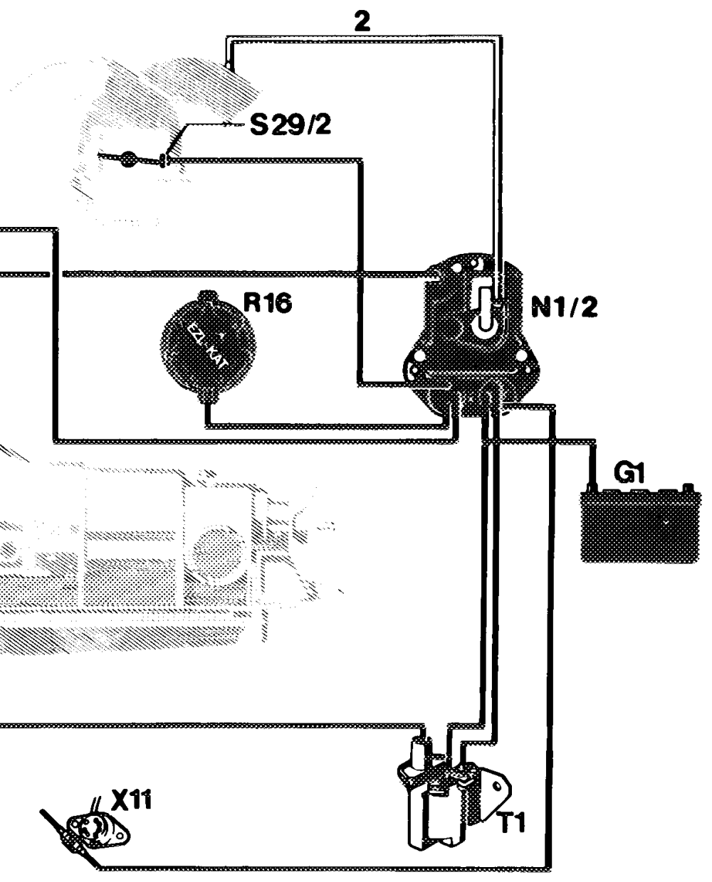
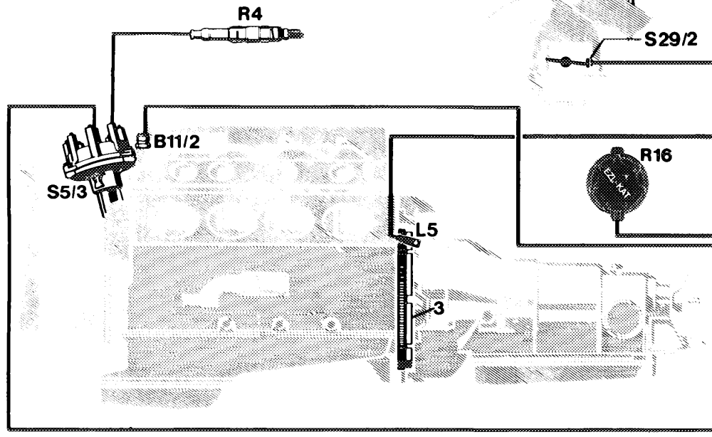
Function diagram of electronic ignition system with electronic timing adjustment (EZL) B11/2 Coolant temperature sensor (EZL/CIS-E) $29/2 Throttle valve switch, full load/idle G1 Battery T1 Ignition coil L5 Crankshaft position sensor x11 Diagnostic socket/terminal block (circuit TD) N1/2 Electronic ignition control unit (EZL) R4 Spark plugs 2 Vacuum line R16 Resistance trimming plug (EZL) – not used 3 Segments on driven plate (R16/1) reference resistor used on USA vehicles. $5/3 High-voltage distributor
Arrangement of components
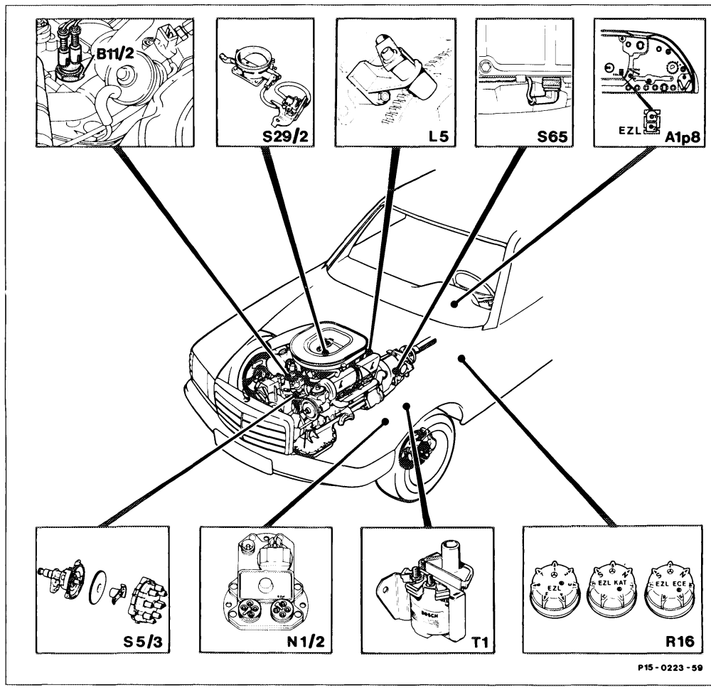
A1p8 Electronic speedometer $5/3 High-voltage distributor B11/2 Coolant temperature sensor (EZL/CIS-E) $29/2 Throttle valve switch, full load/idle Crankshaft position sensor S65 Transmission overload protection switch, brake N1/2 Electronic ignition control unit (EZL) band B1 – not used on USA vehicles R16 Resistance trimming plug (EZL) – not used, T1 ignition coil (R16/1) reference resistor used on USA vehicles
(4-pin supply connector). The vacuum advance is also activated at idling The known functions of dwell angle control, speed, i.e. there is no fixed idle speed curve. primary current cutoff and primary current The ignition timing advance through the limiting are contained in the EZL control unit. reference resistor is also active at idling speed The engine speed-dependent TD signal is (without vacuum). generated in the EZL control unit. When the coolant temperature rises above When the engine is started and up to approx. approx. 95 °C, certain ignition characteristic curves are retarded to counter any further rise 450 rpm, the ignition timing is controlled only via the segment edges of the flywheel. Only after in temperature. a certain engine speed is reached (approx. 460 rpm) is a transition made from the fixed ignition timing to the ignition timing matched to the momentary operating state.
Various ignition characteristic curves are inhibited in the warm-up range depending on the coolant temperature, in order to reach the normal operating temperature as rapidly as possible.
Driven plate with segments
4 segments offset by 90° are fitted to the ring of the driven plate to activate the ignition system.
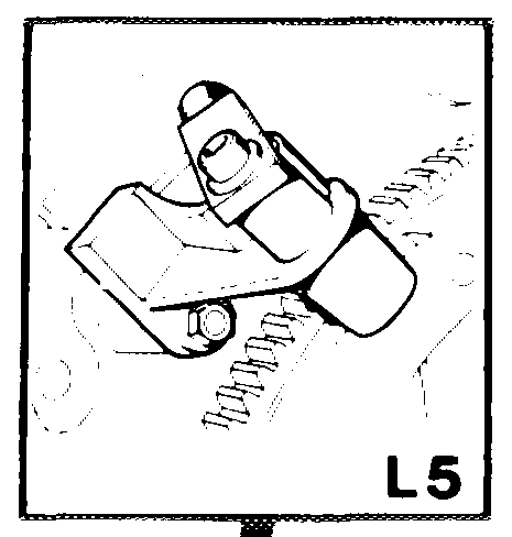
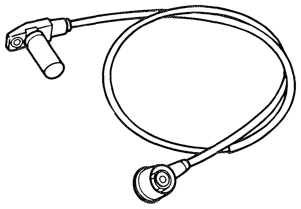
Position sensor (L5)
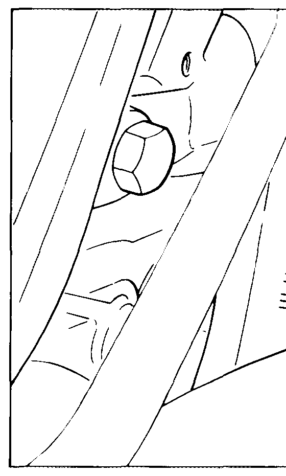
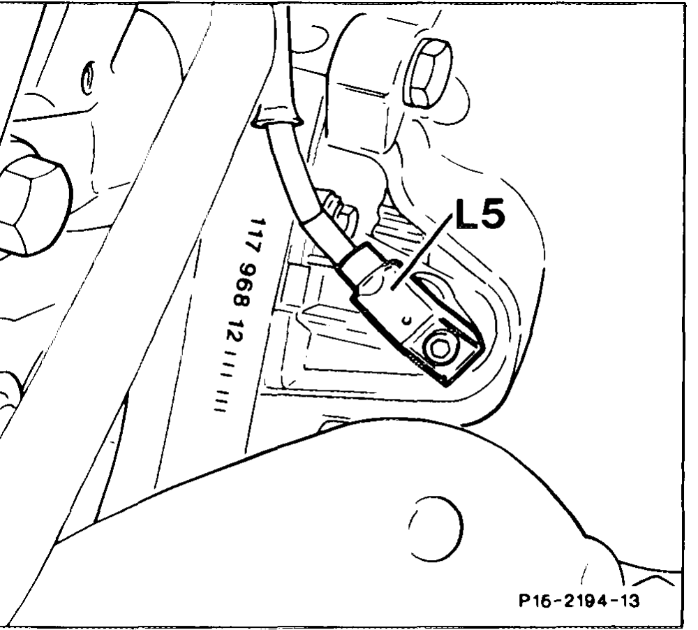
To activate the ignition control unit, the position sensor detects the crankshaft position and engine speed.
The position sensor (L5) is installed on the crankcase above the starter flange.
The coil body projects to shortly before the segments on the driven plate. Segment position and engine speed are detected without physical contact.
When the engine is turning, the induction produces an alternating voltage in the position sensor. The peak value of the voltage (Us) is approx. 1.5 Volts at starter speed. As engine speed increases, the voltage rises (Us approx.
3 Volts at 1200 rpm).
Note Measure peak level of voltage (Us) with the oscilloscope.
The crankshaft position is detected from the P15-2138–13 voltage as follows:
The segment front edge produces a negative voltage signal. The segment rear edge produces a positive voltage signal.
Components and function
EZL control unit (N1/2)
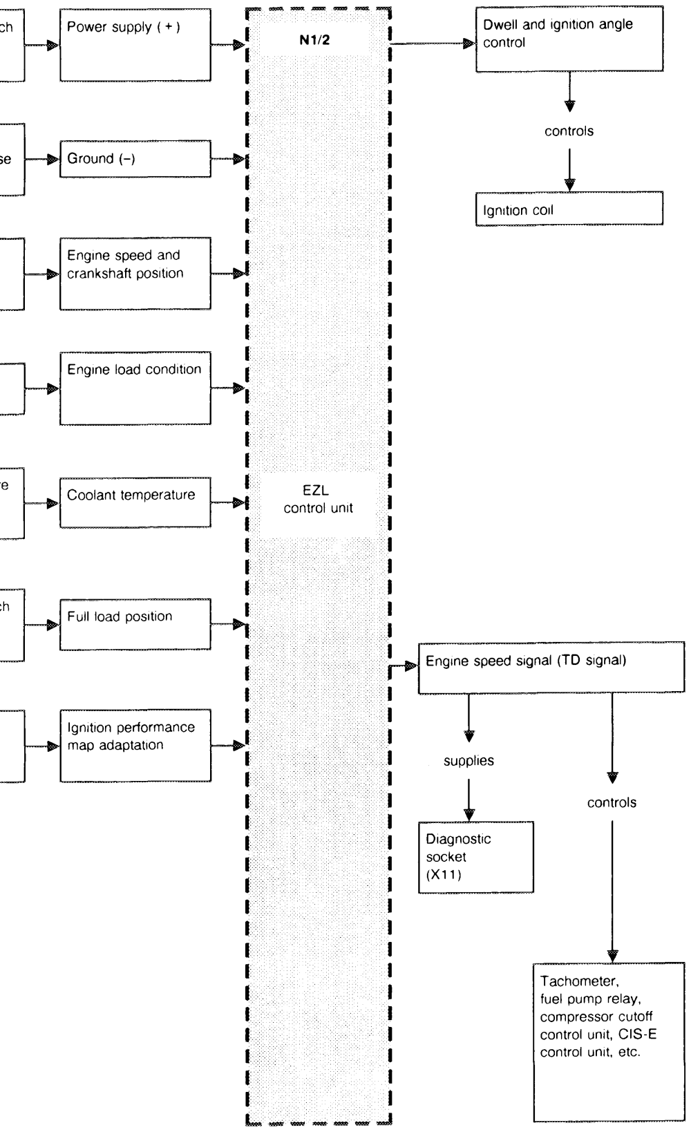
Ignition starter switch (S21) terminal 15
Ground point (W3) front left wheelhouse
Crankshaft position sensor (L5)
Intake manifold vacuum
Coolant temperature sensor (B11/2)
Throttle valve switch (S29/2)
Reference resistor (R16/1) Lo wheelhouse panel.
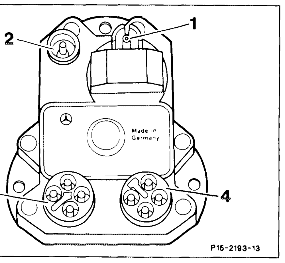
It is installed with heat-conducting paste to dissipate heat. When exchanging this part, the protective foil must not be removed. The foil does not impair heat dissipation. The EZL control unit contains a microcomputer, a pressure sensor and the power output stage.
1 Vacuum connection
2 Coaxial connector for control line from position sensor 3 4-sensor connector
1 Coolant temperature sensor
2 Throttle valve switch
3 EZL reference resistor 4 not assigned (cable ends in cable harness) 4 4-pin supply connector
15 Terminal 15
16 Ignition coil, terminal 1 TDTD signal
31 Ground
The ignition maps for typical load/engine speed ranges and a fixed full load ignition characteristic curve are stored in the microcomputer of the EZL control unit.
The EZL control unit detects the momentary operating state of the engine from various input signals. Engine speed and crankshaft position are detected by the position sensor.
The optimal ignition timing for this operating state is determined from the stored ignition maps taking into account all the input signals.
15.0713 – 510’4
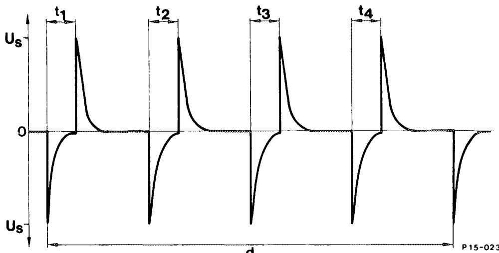
{1 1st segment t2 2nd segment {3 3rd segment t4 4th segment d Period for one crankshaft revolution
Engine speed is calculated by measuring the period for one crankshaft revolution.
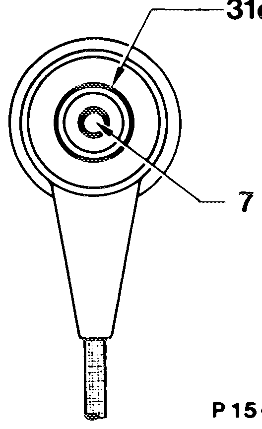
The alternating voltage from the position sensor is passed along the control cable (coaxial cable) to terminal 7 on the EZL control unit. This is a single-core cable with the cable shield being used as the second conductor.
If the EZL control unit does not receive a signal from the position sensor, the complete ignition P15-0240°13 system is inoperable, e.g. the cause may be an interruption in the sensor coil.
The resistance of the position sensor between terminals 7 and 31d is 680-1200 Q.
Instructions regarding damaged segments or mechanical damage to the position sensor:
e@ Alternating voltage from position sensor
below specification.
e Greatly varying alternating voltage signals
form individual segments. e No alternating voltage signal.
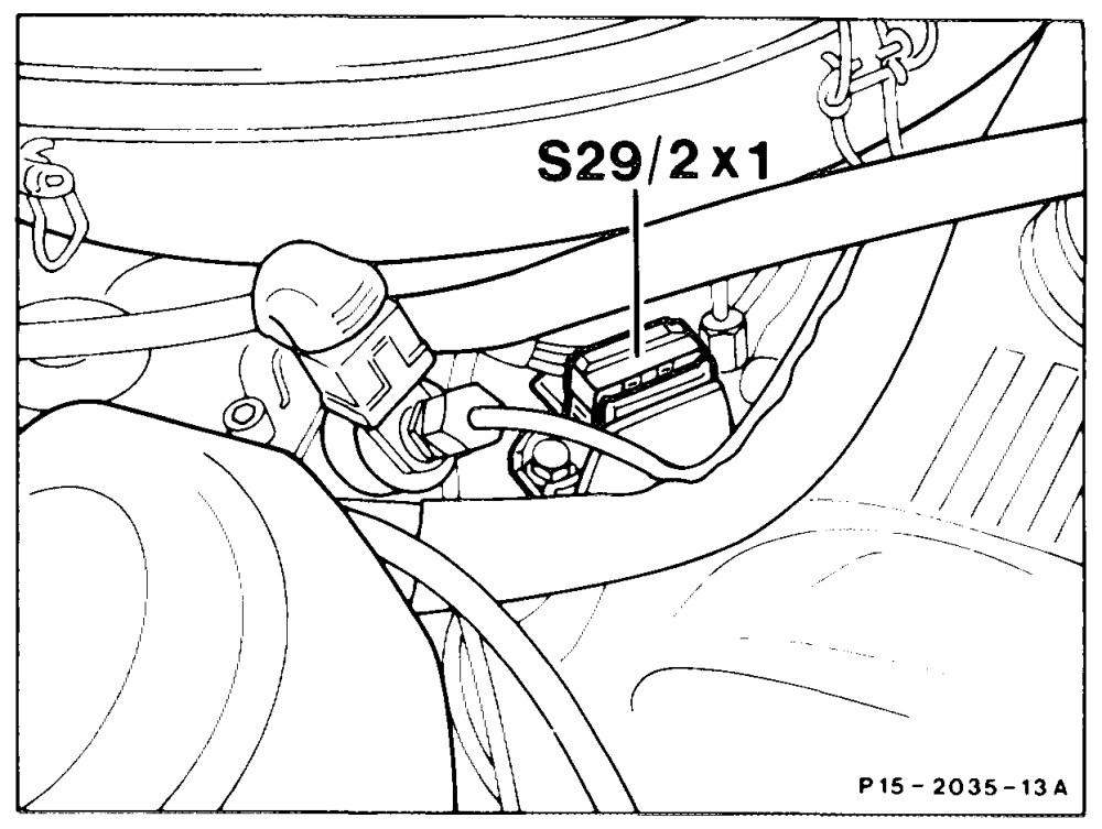
Throttle valve switch (S29/2)
The fixed full load ignition characteristic curve is activated when the full load contact of the throttle valve switch is closed (accelerator in full load position). The switch signal passes through throttle valve switch connector (S29/2x) and the 4-pin sensor connector (contact 2) to the EZL control unit.
Coolant temperature sensor (B11/2)
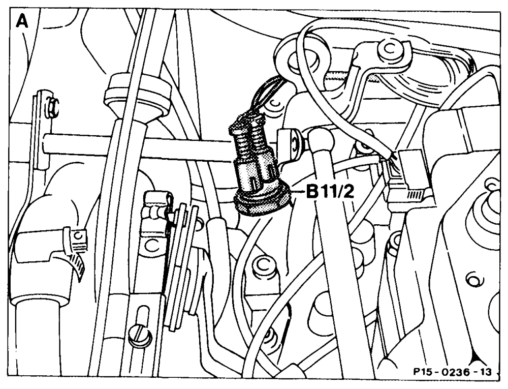
The coolant temperature sensor has two NTC resistors each with a single-pole connection. One NTC for CIS-E and one NTC for EZL. The temperature signal passes along the green:black cable and the 4-pin sensor connector (contact 1) to the EZL control unit. The coolant temperature sensor is positioned at the rear left on the cylinder head (A) or at the front (B).
Note
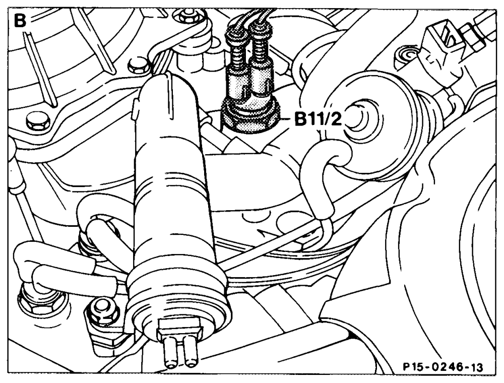
NTC =resistance with negative temperature coefficient, i.e. the resistance is less in the warm state. A 1st version up to January 1986
8 2nd version effective January 1986
EZL reference resistor (R16/1)
The EZL reference resistor (R16/1) possesses a fixed resistance of 750 2.
A particular ignition map in the EZL control unit is activated with the EZL reference resistor (R16/1).
Perform resistance measurement for testing the reference resistor (R16/1) at the EZL control unit between sensor connector (contact 3) and ground. P152189–13
Model 126
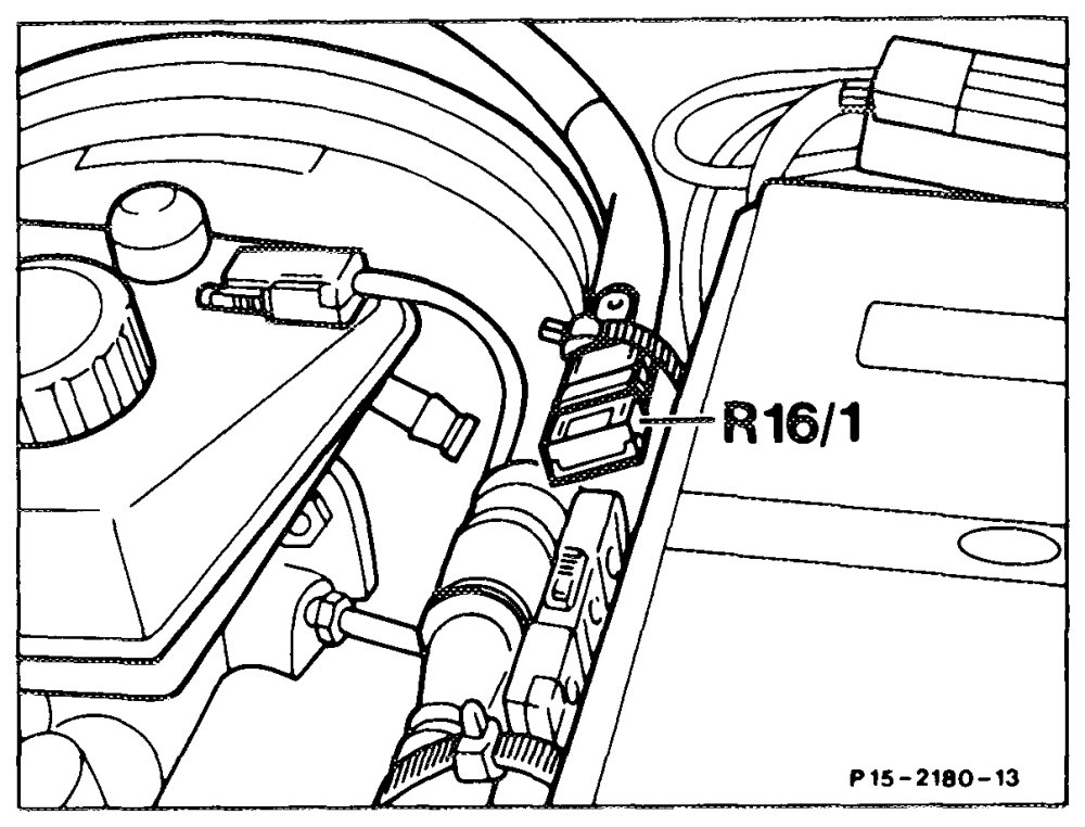
The EZL reference resistor (R16/1) is located between the fuse and relay box and attached to the brake booster at the wiring harness.
High voitage distributor (S5/3)
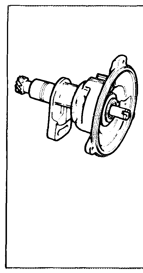
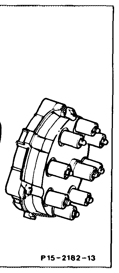
The only task of the high voltage distributor is to distribute the ignition voltage. It is thus no longer possible to adjust the ignition timing. The ignition timing is activated and adjusted by means of the position sensor and the electronic EZL control unit.
Interference suppression resistors: On distributor cap per terminal 1 kQ, spark plug connector 1kQ, distributor rotor 1 kQ.
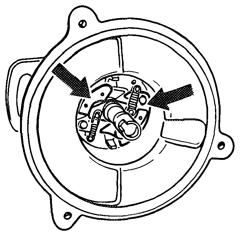
force-dependent advance of the distributor rotor . This ensures that, even with extreme ignition angles, an adequate insulation gap is guaranteed between distributor rotor and the adjacent distributor cap electrodes. However, this necessitates the most accurate possible assignment (setting) between distributor rotor and housing (approx. + 1° CA).
P1§-2178–13
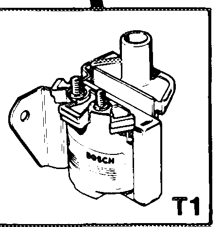
Ignition coil (T1)
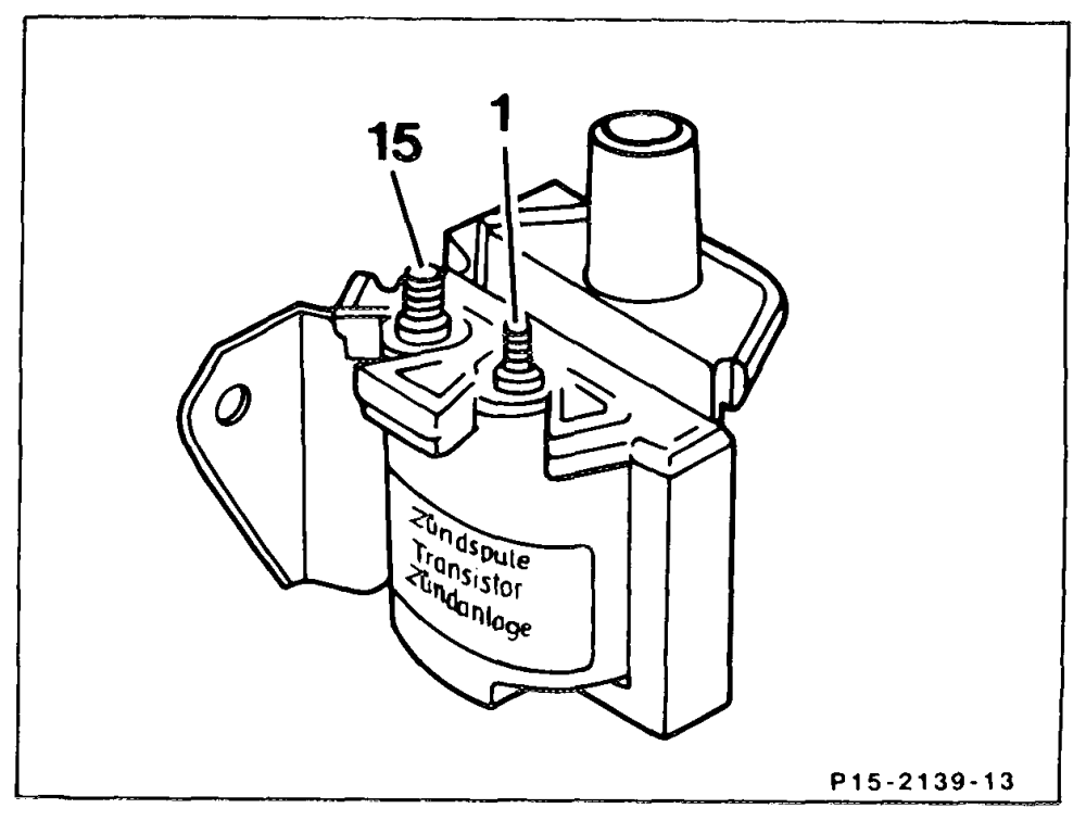
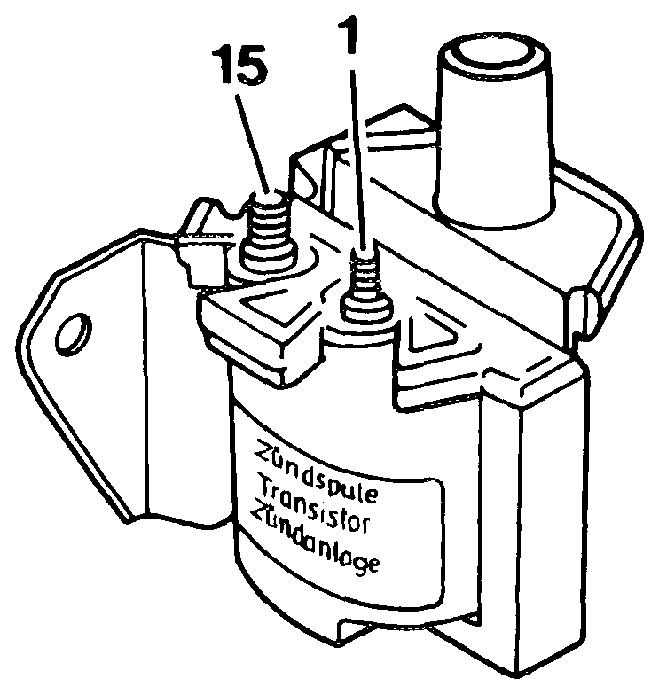
The ignition coil is matched to the EZL control unit to achieve a high ignition energy. As a result of the high switching power of the EZL control unit, the primary current can be further boosted. For this purpose, the primary winding is designed with a very low impedance (0.2–0.4 Q). Closed circuit cutout and primary current limiter enable the ignition coil to be operated without a series resistor. Consequently, the current limiting as a result of the series resistor is eliminated. If the maximum primary current flows in the ignition coil without any limit (e.g. closed circuit current cutoff faulty), the ignition coil will be damaged after a short time as a result of the intense heat which develops.
Distinguishing feature:
The ignition coils on 4and 6-cylinder engines with EZL ignition systems are identical. Identification: yellow type plate. The ignition coils cannot be interchanged with the ignition coils for 8-cylinder engines (identification: green type plate). Pay attention to the Part No. when exchanging parts.
Refer to the instructions for working on electronic ignition systems (15-505).