Adjusting regulating linkage
WIS 30-300
Adjusting data in mm
| Model | 107 | 116 | |
| Length of connecting rod from throttle valve housing to guide lever | 104 | ||
| Length of connecting rod (21) from accelerator pedal to guide lever | 122 | ||
| Length of pushrod (5) from longitudinal regulating shaft to accelerator pedal | 105 | 60 | |
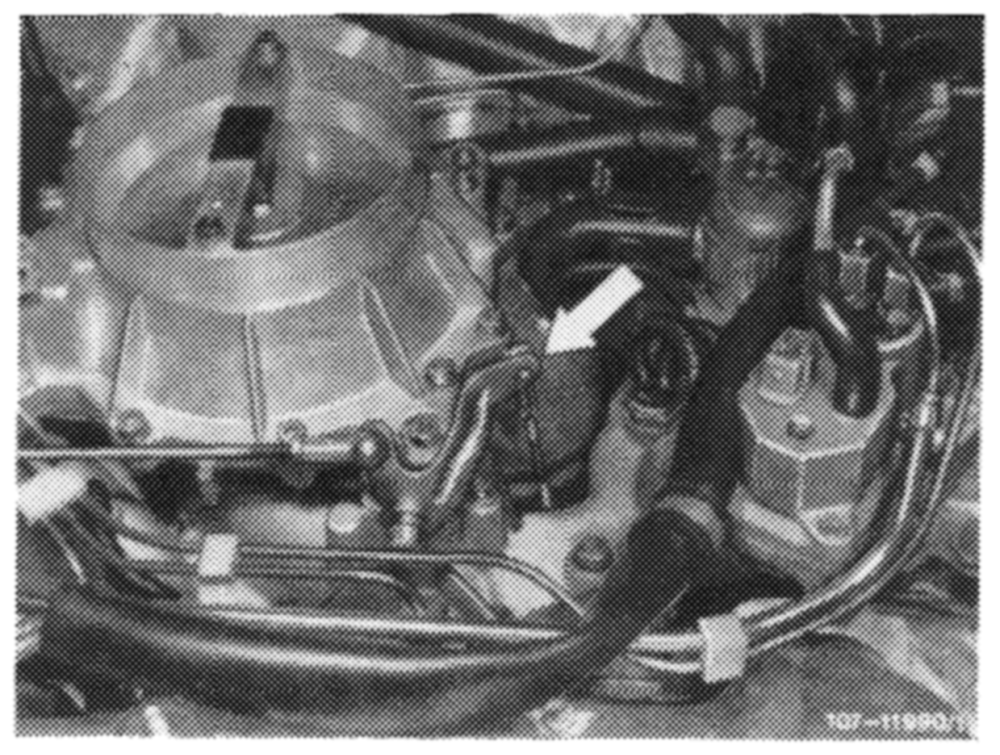
Adjusting
1 Check regulating linkage for easy operation and distortion. Replace linkage, if required.
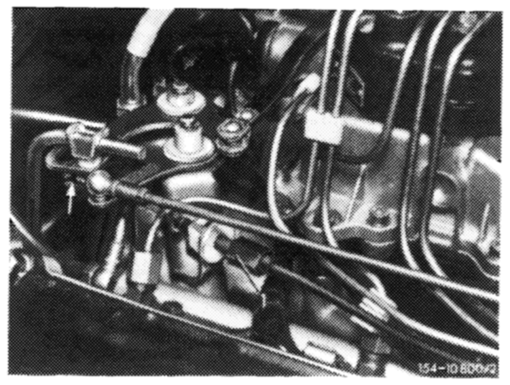
2 Disconnect connecting rod (arrow) on guide lever. Check whether throttle valve rests against idle speed stop. Reattach connecting rod free of tension and set to specified length, if required.
3 Vehicles with cruise control/tempomat. Check whether bowden wire for cruise control/tempomat rests free of tension against regulating lever. Adjust with adjusting screw (1), if required.
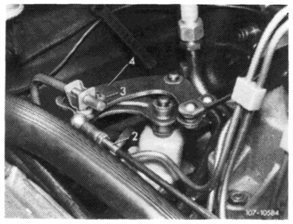
4 Adjust connecting rod (2) in such a manner that roller (3) in gate lever (4) rests free of tension against end stop.
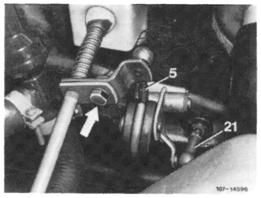
5 With engine stopped, step on accelerator pedal from inside vehicle down to full throttle stop or on automatic transmission up to stop on kickdown switch. The throttle valve lever should rest against full throttle stop. Loosen adjusting screw (arrow) if required, adjust regulating linkage in such a manner that the throttle valve lever rests against full throttle stop.
If full throttle or idle speed stop is not attained with this adjustment, set pushrod (5) from longitudinal regulating shaft to accelerator pedal to specified length, measured from center of ball socket to center of damping ring.
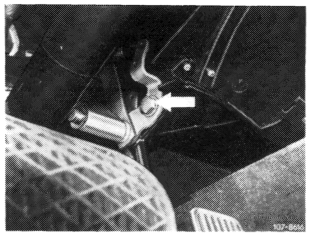
If on model 116 the full throttle or idle speed stop is not attained by means of the adjustment named above, set connecting rod (21) from guide lever engine compartment to accelerator pedal to 122 mm, measured from center of ball socket to center of ball socket. Adjust regulating lever inside vehicle, if required. For this purpose, loosen fastening screw (arrow), pull accelerator pedal slightly in upward direction and tighten fastening screw again.
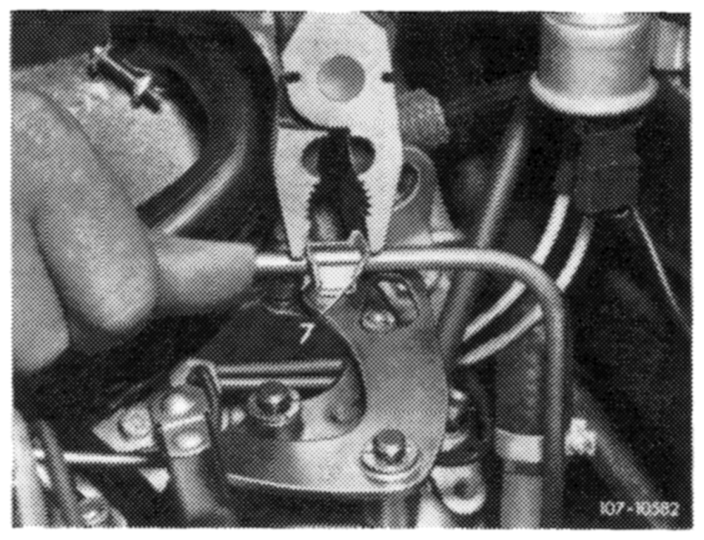
6 Adjust control pressure rod (at idle speed position). For this purpose, compress adjusting clip (7) with pliers and push contro! pressure rod completely to the rear against stop.
Engine regulation
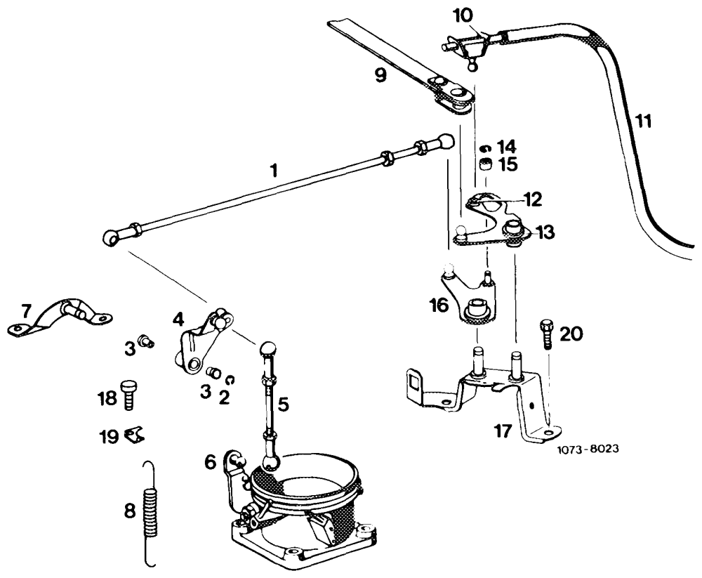
WOONONRWN— Regulating rod Locking ring Plastic bushing Guide lever Connecting rod Throttle valve housing Bearing bracket Return spring Connecting rod to longitudinal regulating shaft Adjusting clip Control pressure rod Plastic bushing Gate lever Locking ring Roller Angle fever Bearing bracket Screw Holder Screw