Installation and centering of intermediate flange
WIS 01-220
Data
Permissible radial runout at fitted shoulder of 0.10 intermediate flange during one full turn
| Permissible axial runout at fitted shoulder of intermediate flange during one full turn Fitted bore in intermediate flange for centering pins Tightening torques | 0.10 12.016 to Nm |
| Fastening screws for intermediate flange Fastening screws M 8 for supporting angle on cylinder crankcase | 50 30 |
Fastening screws M 10 for supporting angle on intermediate flange
initial torque Necked-down screw for driven plate or flywheel angle of rotaton torque
Special tool
Dial gauge holder – 363 589 02 21 00
Self-made tool
Threaded bolt refer to Fig., item 3
Note
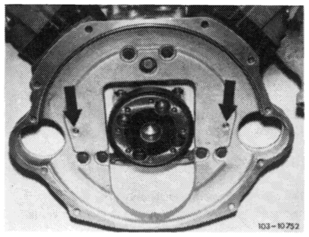
A new intermediate flange must be centered.
Installing and centering
1 Insert intermediate flange into fitted pins (arrows) into crankcase.
2 Slightly tighten the four fastening screws.
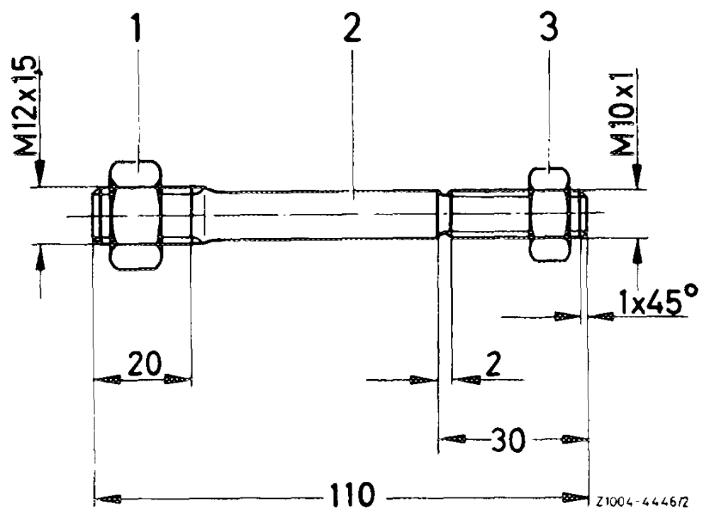
3 Screw threaded bolts into crankshaft and counterlock.
1 Hex. nutM 12 x 1.5 2 Threaded bolt 10 mm dia. 3 Hex. nutM 10x 1
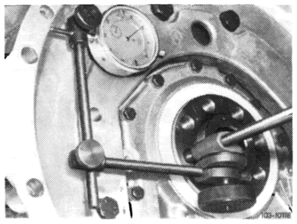
4 Attach dial gauge holder with dial gauge to threaded bolt.
5 Position feeler pin against fitted OD of intermediate flange for measuring axial or radial runout. Set dial gauge to 0.
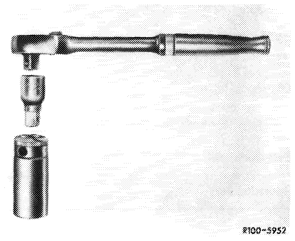
6 Turncrankshaft with tool combination in direction of rotation for one complete revolution. Radial or axial runout should not exceed max. 0.10 mm. This means that the total deflection may amount to max. 0.10 mm. If the axial runout exceeds 0.10 mm, renew intermediate flange.
Note: When rotating crankshaft, make sure that feeler pin of dial gauge is not getting stuck.
7 Correct radial runout by means of light blows against intermediate flange.
8 Tighten fastening screws.
Note: If the radial runout is higher than 0.10 mm, remove intermediate flange.
9 Drill both fitted bores in intermediate flange to 12.1 mm.
10 Repeat item 1—8.
11 Mount supporting angle only after the intermediate flange has been attached to cylinder crankcase.
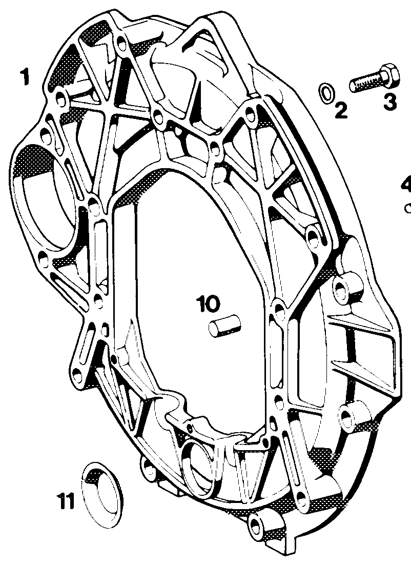
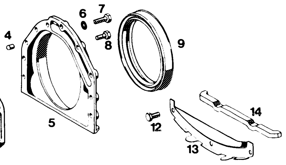
Intermediate flange 1 Spring washer B 10 2 Screw M 10 x 28 3 Cyl. pin 6h 8 x 10 4 5 End cover 6 Washer A 6.4 Screws M6 x 25 (5 each) 7 Screws M6 x 20 (3 each) 8 Radial sealing ring 9
10 Cyl. pin6h8 x 10 11° Cover
12 Screw M6 x 15
13 Cover plate
14 Sealing strip