Viscofan coupling, speed-controlled
WIS 20-320
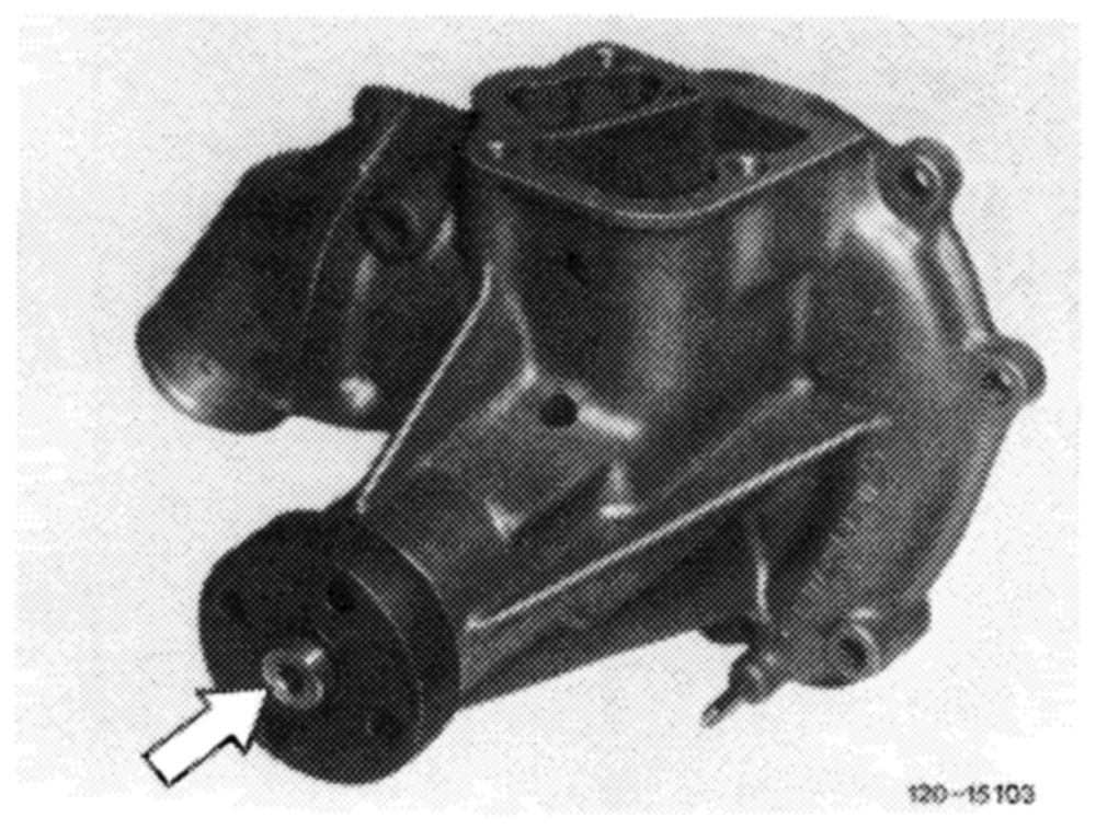
Note The viscofan coupling, part No. 000 200 07 22, has been replaced by the viscofan coupling, part No. 116 200 01 22.
In the event of repairs, the new viscofan coupling
may be installed together with coolant pump, part No. 117 200 03 01.
The coolant pump is identified by the 5 reinforcing fins on bearing housing and on bore (arrow) in coolant pump shaft.
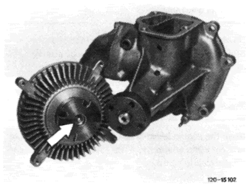
The pin (arrow) in flange shaft prevents mounting the new viscofan coupling on a coolant pump of an older version.
Operation
Note: Data without brackets refer to engines 116, those within brackets to engines 117.
On this type of viscofan coupling, the fan speed depends on the engine speed.
Up to an engine speed of approx. 4650 (3850)/min. the fan runs along proportionally to engine speed, while a fan speed of approx. 3000/min due to the ratio of the belt drive and slip in viscofan coupling may not be exceeded.
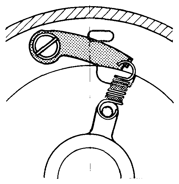
At increasing engine speed, the fan A speed will drop to approx. 500/min and will attain approx. 600/min at max. speed of engine.
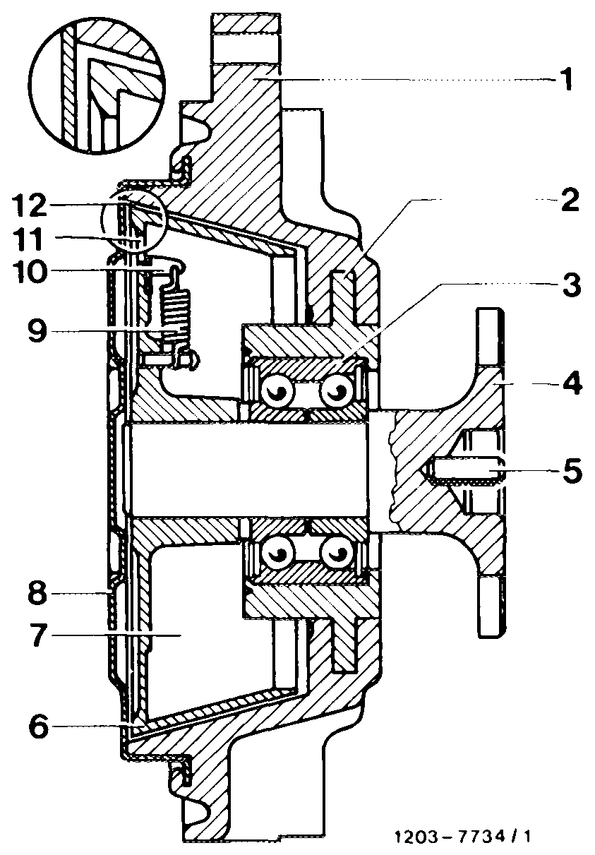
This control step is effected by the spring-loaded closing lever (10), which closes the bore (11) under the influence of centrifugal forces and interrupts the circulation of the power-transmitting fluid.
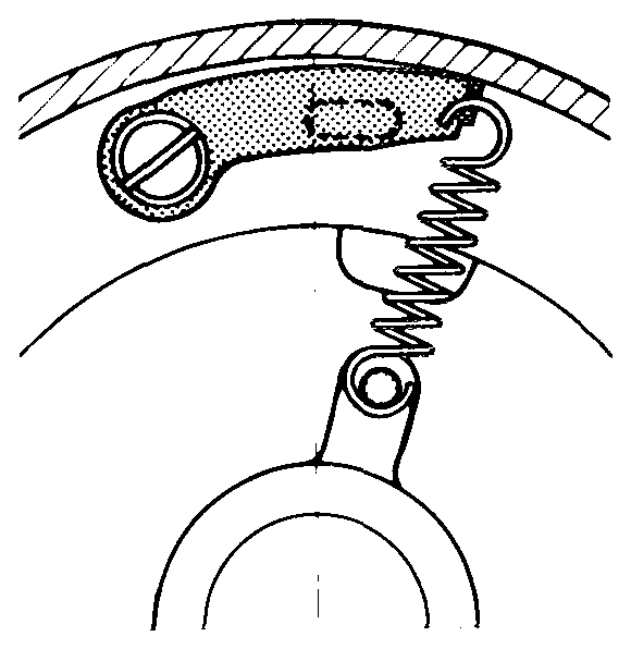
NH-OCODNMDMNAWN— Secondary member Steel bushing Two-row angular contact ball bearing Flange shaft Pin Primary or drive pulley Reservoir Closing cover Closing spring @BWpoos Closing lever Feed bore Work gap Connecting position Disconnecting position
Checking disconnection
Slowly increase engine speed. At max. 4650 (3850)/min, the drop in fan speed can be clearly heard.
Checking connection
When the engine speed drops, the fan coupling should connect again at approx. 4100 (3400)/min, which can also be clearly heard.
Reconditioning
A defective viscofan coupling cannot be repaired with workshop means and must be replaced.