Testing electronically controlled gasoline injection
WIS 07.4-040
A. With Bosch tester EFAW 228
Conventional tool
made by Bosch GmbH Bosch tester EFAW 228 D-7000 Stuttgart 30
Connection diagram for control unit
The following wiring diagram shows the individual components of the electronically controlled gasoline injection system and its connection to the control unit.
Engine 116
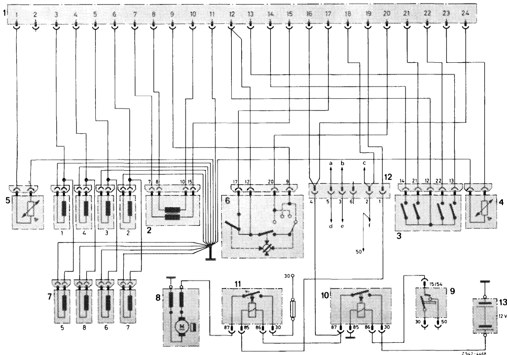
1 Multi-point connector control unit 7 Injection valves 12 Plug connection to vehicle harness
2 Pressure sensor 8 Fuel pump a To cold starting valve
3 Release contacts in ignition distributor 9 Ignition starting switch b To thermo-time switch terminal W
4 Temperature sensor cooling water 10 Main relay electronic system c To thermo-time switch terminal G
5 Temperature sensor air 11. Pump relay dTo cold starting relay terminal 87
6 Throttle valve switch e To cold starting relay terminal 85 Terminal 9 transition enrichment f To cold starting relay terminal 86 Terminal 20 transition enrichment 13. Vehicle battery Terminal 12 ground Terminal 17 idle speed contact
Engine 117
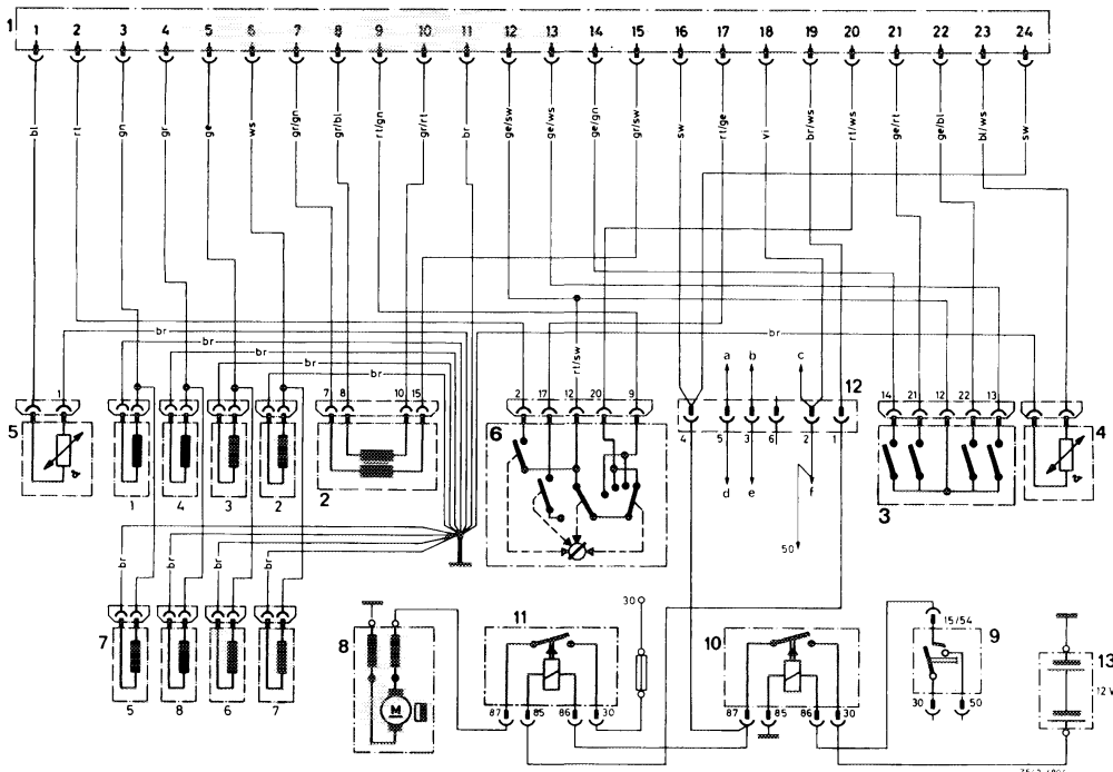
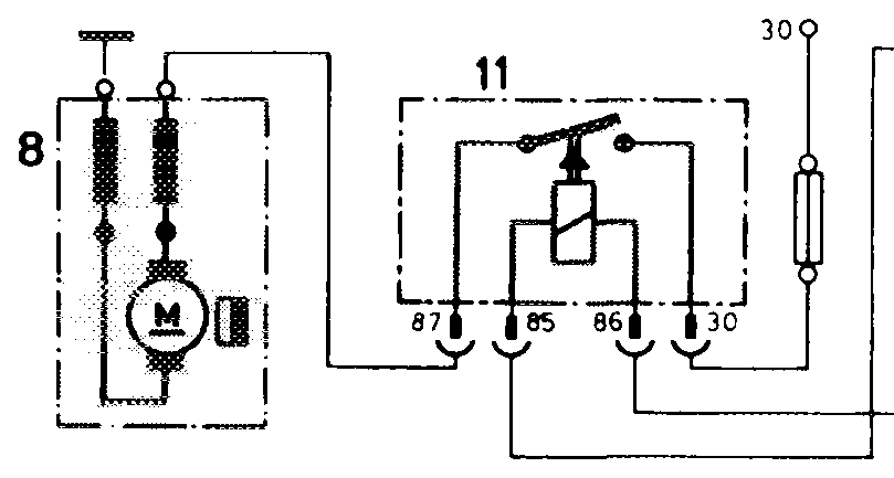
1 Multi-point connector 6 Throttle valve switch 9 Ignition starting switch Relay for starting (control unit) Terminal 9 transition 10 Main relay (power valve terminal 87
2 Pressure sensor enrichment supply control unit) Relay for starting valve
3 Release contacts Terminal 20 transition 11 Pump relay terminal 85 (ignition distributor) enrichment 12 Intermediate plug Relay for starting valve
4 Temperature sensor Terminal 2 full-toad (connection to vehicle terminal 86 (coolant) contact harness) 13 Vehicle battery
5 Temperature sensor (air) Terminal 17 idle a Starting valve speed-contact b Thermo-time switch Terminal 12 ground terminal W 7 Injection valves cylinder c Thermo-time switch 1-8 terminal G 8 Fuel pump
Relay layout
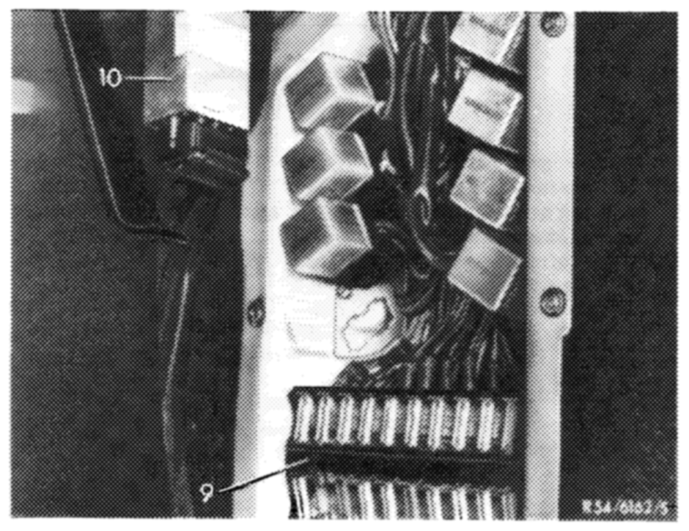
| Code number | Relay function |
| 1 2 3 | Relay fuel pump Relay starting valve Main relay electronic injection |
Model 107
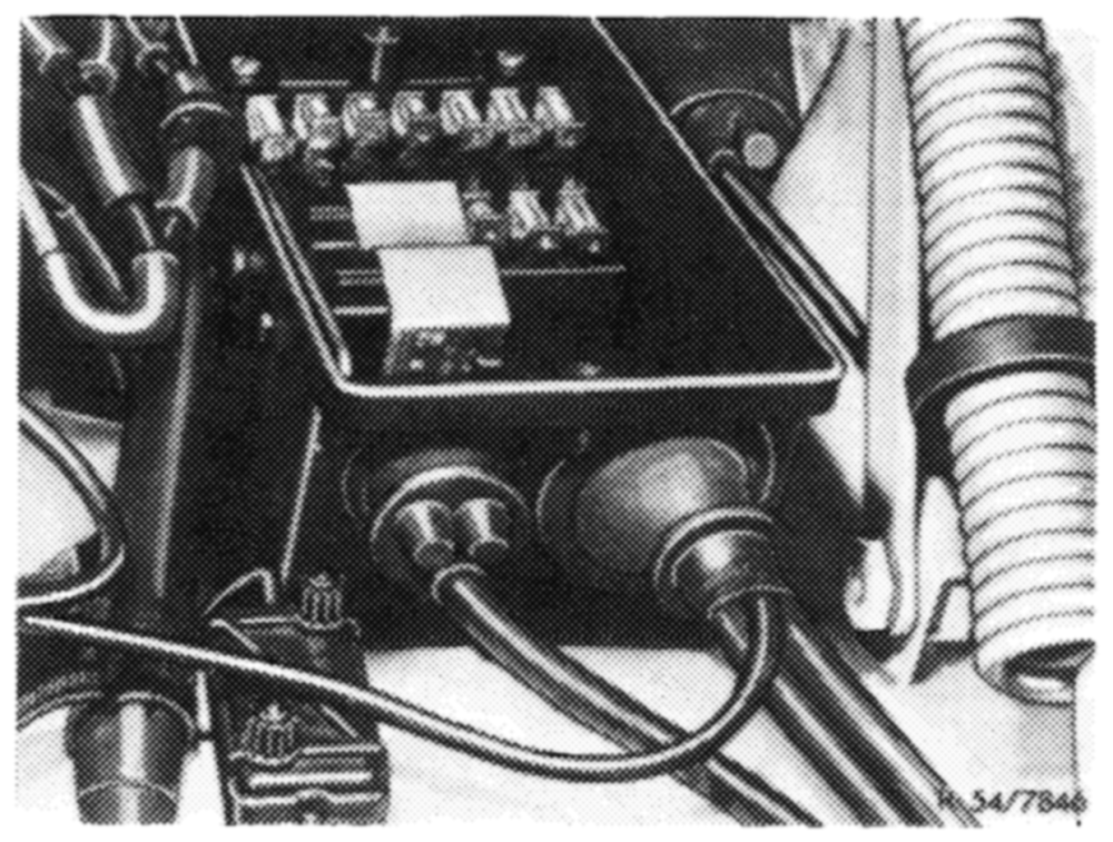
Model 116
Initial jobs for testing refer to 07.4–035.
|. With control unit not connected
| ,,A”’ on tester to position ,, measuring’, switch on ignition and complete all functions according to check list. | omplete all functions according to – | |
| ,,B” in Actuate Measure | Indication (nominal value volt-ohmmeter) | Nominal value not attained. Possible causes and remedy |
Voltage Switch-on ignition Voltage supply for 11…12.5 Voltmeter indicates no voltage: contro! unit (11…12.5 V) Interruption: Plug connection from main and leave switched relay (10) to control unit (line 16). on throughout entire Main relay not attracting: Check voltage test sequence deson terminal 86 of main relay, if there is cribed below no voltage, check fuse in fuse box. Terminal 85 should be connected to ground, Measure voltage on terminal 87 of relay. If voltage is ,,0’’, check terminal 30 of relay.
Under load, voltage is below 11 V:
Transfer-resistance on line 16 or on relay contact. Exchange main relay. Check cable from battery terminal plus to relay terminal 30. Similar to voltage |, but check line 24.
Voltage II
Voltmeter shows no voltage, but starter Voltage starter Voltage on 9.0…12.0 Actuate starter terminal 50 of (9.0…12.0 V) for a moment rotates: Line interruption from starter terminal starter 50 to control unit. Check line to control unit terminal 18.
Voltmeter indicates no voltage and
starter is not rotating: Ignition starting switch defective, line interrupted. Voltage below 9.5 V: Battery discharged, voltage drop in line from ignition starter switch to terminal 50 of starter relay too high. Measure line with voltmeter for voltage drop.
Adjust instrument by turning Alignment °° \f no full deflection is attained on aligning knob to instrument, battery voltage in vehicle pressure sensor is too low. Also refer to test step: Voltage I.
Resistance Resistance ,,°°”’ Push button Resistance ,,0°’: between pressure (oo) ground” Ground connection in supply line or on pressure sensor. Pull plug from pressure sensor windings and ground sensor, if indication is ,,°°’’, exchange (ground connection) pressure sensor; if indication remains unchanged at ,,0”, lines 7, 8, 10 or 15 may have a short circuit, replace cable harness. Resistance below ,,°°’’, but not ,,0”: Insulation damage, remedy see above.
Nominal value not attained. Measure Indication Switch ,,B” in Actuate (nominal value Possible causes and remedy in position volt-ohmmeter)
0.8…1.20n ohm
Resistance essentially lower than
Resistance of Push ,,primary”’ Alignment ~, scale (approx. primary winding
nominal:
button pressure sensor 90 ohms) Insulation damage: Pull plug from of pressure sensor pressure sensor, if indication then is »%”, exchange pressure sensor. Resistance ,,0”: Short circuit in winding. Pull plug from pressure sensor, if indication then is exchange pressure sensor. Resistance considerably higher than
nominal:
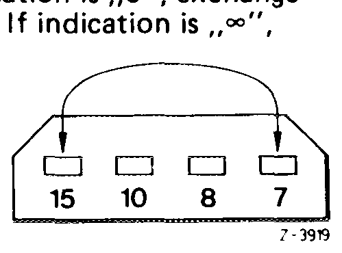
High transfer resistance. Check plug and lines for corrosion or interruption. Resistance Interruption. Bridge terminal 7 and 15 on plug. !f indication is ,,0’’, exchange pressure sensor. check lines.
Top view on plug
| Push ,,secondary”’ button | Resistance of secondary winding of pressure sensor | 3…40nohm scale (approx. 350 ohms) | Similar to »Primary’’. If resistance is bridge terminals 8 and 10. | Mom 5 | 10 | 8 | 7 N ~3920 | |
| ZV contact ZV contact II ZV contact III ZV contact IV | Rotate ignition distributor by brief actuation of starter | Function of release contact in ignition distributor | Alternately resistance ,,0’’ and (0/°° ohms) | If the pointer of the instrument is not swinging back and forth while starting or stops in position ~ or 0, check connec- tions 12, 13, 14, 21 and 22 on contact stide-in. !f connections and cable harness to control unit are in order, renew release contacts, adjustment is not possible. | ||||
| Throttle valve switch then throttle vaive switch I! | Step down slowly on accelerator pedal | Function of transfer enrichment | Pointer of instrument swings approx.10 times between and ,0 ,,.0″” (alternately 0/e- ohms) | When the floored gas pedal is moving back, the pointer of the instrument should remain in position Indication ,,0″: Throttle valve switch defective, exchange. | ||||
a) Resistance a) Throttle valve a) 0 (0 ohm) Throttle Function of in idle position contact in Throttle valve switch wrongly set or
valve
(closed)
switch III
throttle valve interruption in supply line. Check adjustment. Pull-off plug, bridge terminals switch 12 and 17. If then still exchange cable line, otherwise exchange throttle valve switch.
C) 14 ooo co ooo 9 20 12/14 17 9 20 4742 17 14/2 ‘2154-40371 ~ 2154-4523/2 Engine 116 Engine 117 b) 2 (2 ohm) b) Throttle valve b) Resistance ,,0”: slightly opened Throttle valve switch wrongly adjusted approx. 1° = 0.4mm or short circuit in supply line. Pull-off plug, if indication is still ,,0”, exchange cable line, otherwise adjust or exchange throttle valve switch.
(ZV = ignition distributor)
Checking throttle valve switch — full-load contact (refer to section II, item Pressure switch).
| Switch ,,B” in Actuate Position… | Measure | Indication (nominal value voltohmmeter) | tinal Nominal value not attained. | Possible causes and remedy. |
| Temperature sensor (intake air) | Resistance of temperature sensor | 2… 5at 20°C heavily dependent on temperature: 64082 at 0°C 400 2 at 10°C 300 22 at 20°C 210Q 30°C at 150 Q at 40°C | Nominal value applies to 20°C. Resistance becomes lower at higher temperature. If measurements are not O or ©, sensor is in order. Indication Interruption. Pull-off plug and bridge, if indication is ,,0’’, exchange temperature sensor, otherwise cable line. Indication ,,0”: Short circuit. Pull-off plug, if indication remains unchanged. Cable is defective. If indication then is exchange temperature sensor. | |
| Temperature sensor {1 (cooling water) | Resistance of temperature sensor | 0.2…0.4 at 80°C heavily dependent on temperature: 5.9kQat 25kQat 1.2kQat 40°C 600 Qat 60°C 325 Qat 80°C 190 Qlat 100°C | 0°C 20°C | Refer to temperature sensor |. Nominal value applies to 80°C cooling water temperature. |
Valves Button 1 = valves Resistance ,,0″’: Resistance of 2…3 (2.4 Qat 20°C) Short circuit in supply line or on valve. if required, cyl. 1 and 5 valve winding Pull plug from respective valve, if indicabalance instrument Button 2 = valves with supply once again to cyl. 3and6 tion then is ,,~’’, exchange valve, line 2’ (switch posiButton 3 = valves otherwise exchange cable line. tion ,,valves’’) cyl. 2and 7
Resistance
Button 4 = valves Interruption in supply line or in valve cyl. 4and8 coil. Bridge contacts in valve plug, if indication then is ,,0″’, valve is defective.
Attention! Prior to actuating Resistance above ,,3″’: buttons Ground line of valves poorly connected always pull one to engine. valve plug on injection valve, so that only one valve is measured, e.g. cylinder 1 or 5, or 2o0r7.
| in Actuate Measure | Indication | Nominal value not attained. |
| (nominal value | Possible causes and remedy. | |
| has | volt-ohmmeter) | Te |
No pressure buildup (pump not starting).
Valve test
Push ,,pump”’ Connect pressure Nominal value gauge. Pressure 2.0 + 0.1 bar Disconnect cable connections on pump, button push ,,pump” button and measure in fuel line gauge pressure voltage with voltmeter at cable ends. 12 volts readout indicates defective pump, exchange. If indication is ,,0’, check audibly whether pump relay attracts. If yes, line interrupted from pump relay 87 to pump connections or from there to ground. Fuse in fuse box defective. If connecting line is in order, pump relay is defective. If no, line interrupted from main relay terminal 87 to pump relay terminal 86 or from pump relay terminal 85 to control unit terminal 19 (ground for pump relay). If line is in order, check wehether pump relay attracts when ground is connected directly to terminal 85, if yes, exchange control unit, if no, exchange pump relay.
Pressure not corresponding to nominal
value. Pressure regulator maladjusted, adjust Pressure regulator and exchange, if required.
Briefly push Leak test of fuel
Pressure drops immediately upon
Pressure may drop system (Pressure pump” button to 1.5 bar gauge
release of ,pump”’ button below 1.5 bar
end) pressure, then
gauge pressure
pressure should con-1_ Leaks in pressure line system, check tinue to drop only visually whether hose connections slightly are leaking. 2. Leaking valve of delivery pump, of Pressure regulator, of injection valves or of cold starting valve. To check which of the 4 components is leaking: Pinch pressure hose between fine filter and injection valves with delivery pump running by means of a clamp, switch off delivery pump. If the pressure is no longer dropping, valve in delivery pump is defective, exchange delivery pump. But if Pressure still drops: Check pressure regulator. Pull return flow hose from pressure regulator immediately after stopping delivery pump. If fuel emerges, replace pressure regulator. !f no fuel emerges and pressure is still dropping: Determine by means of spark plug patterns whether individual injection valves or cold-starting valve are leaking. Deviations among plug patterns point to leaking injection valves, while uniformly dark plug patterns point to a leaking starting valve. Check accurately upon removal! of valves, connected to pressure system, with delivery pump engaged. Valve opening may become wet. But there should be no more than two drops per minute.
| Switch ,,A”’ in position… (switch ,,B’’ has no influece) | Actuate | Measure | Indication (nominal value volt-ohmmeter) | Nominal value not attained. Possible causes and remedy. |
| Attention! Perform the following test only if a fault is suspected on injection valve. Valves removed. | Pressure buildup: Push ,,pump” button. Push buttons 1 to 4 one after the other. When pushing buttons, pull-off respective plug of valve in valve group not tested at the moment. | Visual checkup. Valve spray test. Catch fuel. | Push ,,pump” button and check visually for leaks. Valve opening may become wet, but there should be no more than 2 drops per minute on one valve. If no leak is found, exchange pressure regulator. | |
| Starting valve cooling water temperature above +35°C | a) Push ,,pump” button, actuate starter for one second. b) Connect connection ,,W” of thermo-time switch to ground. | Function of thermo-time switch and starting valve | a) Pressure gauge should not visibly drop. b) Starting valve injects, pressure gauge indication drops. | a) Pressure drops steadily when starter is actuated. Thermo-time switch defective, exchange. b) Pressure not dropping when starter is actuated Check lines from starting valve to connection 87 of relay or to ground. If connecting lines are in order, check starting valve. Note: Starting approx. September 1975, relays are no longer installed. |
| Cooling water temperature below +35°C | Push ,,pump”’ button, actuate starter for one second (thermo- time switch again normally connected) | Pressure should drop. | If pressure is not dropping, renew thermo-time switch or check starting valve as described under b). Interturn resistance 4.2 ohms at 20°C. |
Switch off ignition, remove pressure gauge.
Il. With control unit connected
| Connect multiple plug of tester to control unit. The position of switch ,,B’’ on tester has no influence on test sequence. | init. The position of switch 8″ on tester has no influence on test sequence. – | |||
| Switch ,,A”’ in position | Actuate | Measure | Indication (nominal value volt- ohmmeter) | Nominal value is not attained. Possible causes and remedy. |
| ZV contact 2V contact II 2V contact HI ZV contact IV | Rotate ignition distributor by operating starter for a short moment | Function of release contacts in ignition dis- tributor | Alternately resistance ,,10″ and (0/ee ohm) | |f the needle of the instrument is not swinging while starting or remains in position or 0, check connections 12, 13, 14, 21 and 22 on contact slide-in. {f connections and cable harness for control unit are in order, renew release contacts. Adjustment is not possible. |
| Pressure switch engine 117 only | Switch on ignition step down on accelerator pedal (full throttle) | Function of full throttle contact in throttle valve switch | 2–5 on volt scale. tndication should come 5° before com- pletely opened throttle valve. | Throttle valve switch defective, exchange. |
B. With volt-ohmmeter
Conventional tools
Ohmmeter 0–10 000 ohm, voltmeter O—16 volt
Connection diagram for control unit
The following circuit diagram shows the individual components of the electronically controlled gasoline injection system and its connection to control unit.
Engine 116
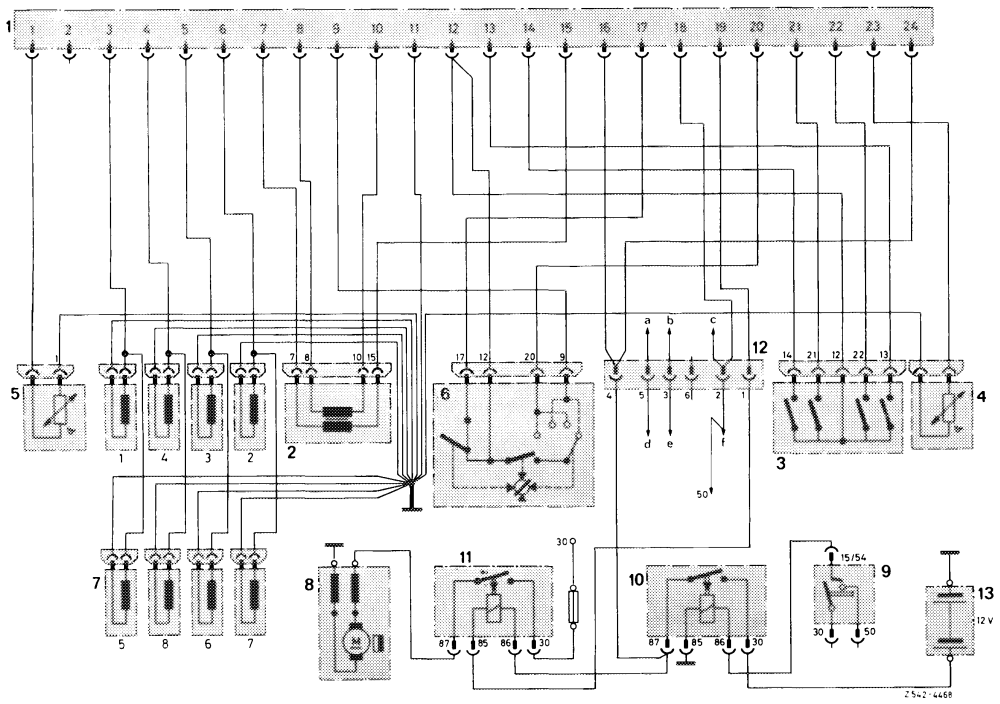
1 Multi-point connector, control unit 7 Injection valves 12 Plug connection to vehicle harness
2 Pressure sensor 8 Fuel pump a Tocold starting valve
3 Release contact in ignition distributor 9 Ignition starting switch b To thermo-time switch terminal W
4 Temperature sensor coolant 10 Main relay electronics c To thermo-time switch terminal G
5 Temperature sensor air 11. Pump relay d To cold starting relay terminal 87
6 Throttle valve switch e Tocold starting relay terminal 85 Terminal 9 transmition enrichment f Tocold starting relay terminal 86 Terminal 20 transition enrichment 13 Vehicle battery Terminal 12 ground Terminal 17 idle speed contact
Engine 117
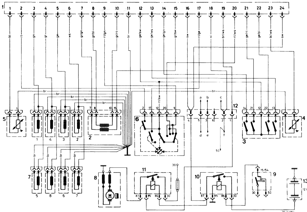
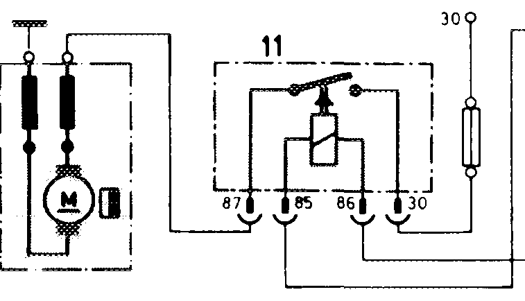
1 Multi-point connector (control unit) 7 Injection valves cylinders 1-8 12 Intermediate plug (connection to vehicle
2 Pressure sensor 8 Fuel pump harness)
3 Release contacts (ignition distributor) 9 Ignition starting switch Starting valve @
4 Temperature sensor (coolant) 10 Main relay (power supply b Thermo-time switch terminal W
5 Temperature sensor (air) control unit) Thermo-time switch terminal G c
6 Throttle valve switch 11. Pump relay d Relay for starting valve terminal 87 Terminal 9 transition enrichment Relay for starting valve terminal 85 e Terminal 20 transition enrichment f Relay for starting valve terminal 86 Terminal 2 full-load contact 13 Vv ehicle battery Terminal 17 idle speed contact Terminal 12 ground
Relay layout
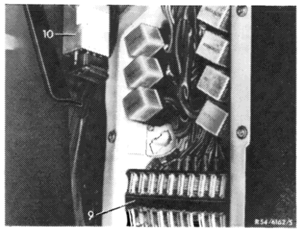
Code number Relay function
1 Relay fuel pump
2 Relay starting va Ive 3 Main relay electronic injection
Model 107
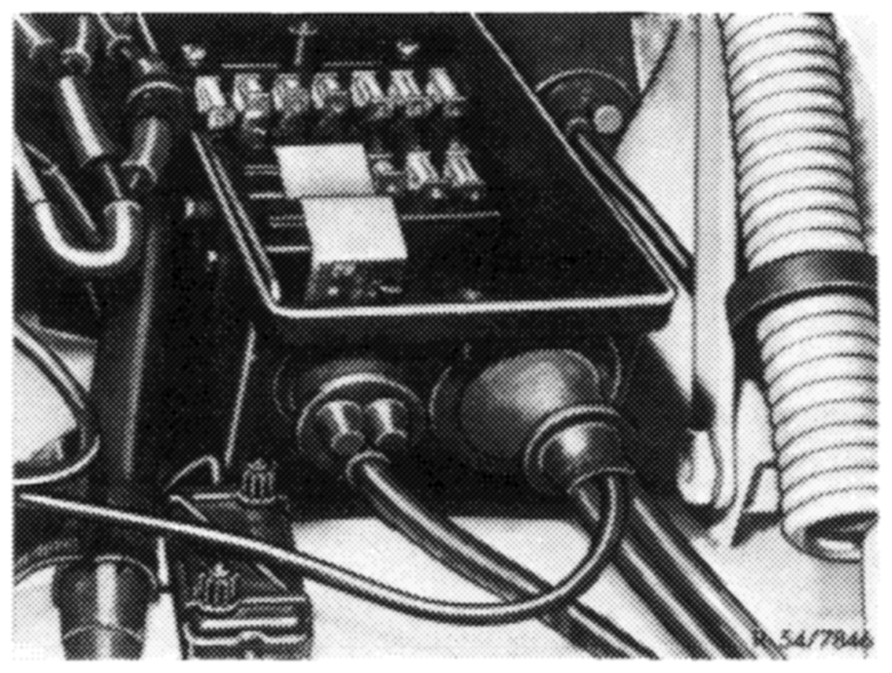
Model 116
Initial jobs for testing (refer to 07.4—035)
Testing
Voltage at multi-point connector of control unit
Actuate: Switch-on ignition and leave switched on throughout entire test sequence described below.
Measure: Voltage supply for control unit.
Connection electronic control Voltage terminal 11 and terminal 16 unit multi-point contactor: Voltage II terminal 11 and terminal 24
Nominal value: 11V
Nominal value not attained.
Possible causes and remedy:
Voltmeter indicates no voltage:
Interruption: Plug connection from main relay (10) to control unit (line 16). Main relay not attracting: Check voltage on terminal 86 of main relay, if there is no voltage, check fuse in fuse box. Terminal 85 should be connected to ground. Measure voltage on terminal 87 of relay. If connection is ,,0″, check terminal 30 of relay.
Under load, voltage is below 11 V:
Transfer resistance on line 16 or on relay contact. Exchange main relay. Check cable from battery terminal plus to relay terminal 30.
Voltage starter terminal 50
Starter Actuate:
Voltage on terminal 50 Measure:
Terminal 11 and terminal 18 Connection electronic control unit multi-point contactor:
9.5 V Nominal value:
Nominal value not attained.
Voltmeter shows no voltage, but starter rotates:
Possible causes and remedy: Line interruption from starter terminal 50 to control unit terminal 18.
Voltmeter indicates no voltage and starter is not rotating:
Ignition starting switch defective, line interrupted terminal 50.
Voltage below 9.5 V:
Battery discharged, voltage drop in line from ignition starter switch to terminal 50 of starter relay too high. Measure line with voltmeter for voltage drop.
Pressure sensor
Pressure sensor connected to ground. Measure:
Connection electronic control Terminal 7 and terminal 11 Terminal 8 and terminal 11 unit multi-point contactor:
Resistance Nominal value:
Nominal value not attained.
Possible causes and remedy:
Resistance ,,0’’:
Ground connection in supply line or on pressure sensor. Pull plug from pressure sensor, if indication is ,,0°’’, exchange pressure sensor; if indication remains unchanged at ,,0”, lines 7 and 8 may have a short circuit, replace cable harness.
Resistance below but not ,,0’: Insulation damage, remedy see above.
Measure: Primary winding of pressure sensor.
Connection electronic control unit multi-point contactor: Terminal 7 and terminal 15
Nominal value: approx. 90 ohms
Nominal value not attained.
Possible causes and remedy:
Resistance essentially lower than nominal:
Insulation damage: Pull plug from pressure sensor if indication then is ,,00’, exchange pressure sensor.
Resistance ,,0”:
Short circuit in winding. Pull plug from pressure sensor, if indication is then ,,00″”, exchange pressure sensor. Resistance considerably higher than nominal: High transfer resistance. Check plug and lines for corrosion or interruption.
Resistance ,,°0’”: Interruption. Bridge terminal 7 and 15 on plug. If indication is ,,0”, exchange pressure sensor. If indication is ,,0’’, check lines.
i Top view on plug onro ao 10 «68
Secondary winding of pressure sensor. Measure:
Connection electronic control Terminal 8 and terminal 10 unit multi-point contactor:
approx. 350 ohms Nominal value:
Nominal value not attained. Similar to ,,primary’’. If resistance is (s Possible causes and remedy: °c, bridge terminals 8 and 10. 6 0 7-390
Function of release contacts in ignition distributor
Rotate ignition distributor by brief actuation of starter. Actuate:
Function of release contact in ignition distributor. Measure:
Connection electronic control ZV contact terminal 12 and 21 ZV contact I! terminal 12 and 22 unit multi-point contactor: ZV contact II! terminal 12 and 13 ZV contact !V terminal 12 and 14
Alternately resistance ,,0″’ and ,,” Nominal value:
Nominal value not attained.
Possible causes and remedy: If the pointer of the instrument is not swinging back and forth while starting or stops in position or 0, check connections 12, 21, 22, 13 and 14 on contact slide-in. If connections to control unit are in order, renew release contact, adjustment is not possible.
Throttle valve switch conductor path and II
Actuate: Step down slowly on accelerator pedal.
Measure: Function of transfer enrichment.
Connection electronic control terminal 9 and terminal 12 unit multi-point contactor: I] terminal 20 and terminal 12
Nominal value: Pointer of instrument swings approx. 10 times between ,,0″ and ,,°0″’
Nominal value not attained.
Possible causes and remedy: When the floored pedal is moving back, the pointer of the instrument should remain in position
Indication ,,0″:
Throttle valve switch defective, exchange.
Throttle valve switch III
Actuate: 1. Throttle valve switch at idle (closed). 2. Throttle valve switch slightly opened (approx. 19 = 0.4 mm).
Measure: Function of contacts in throttle valve switch.
Connection electronic control unit multi-point contactor: Terminal 12 and terminal 17
Nominal value: 1. ,,0″ 2. oot
Nominal value not attained.
Possible causes and remedy: a) Resistance ,,°”’: Throttle valve switch wrongly set or interruption in supply line. Check adjustment. Pull-off plug, bridge terminals 12 and 17. If then still ,,2°”’, exchange cable line, otherwise exchange throttle valve switch.
oOo oOo oY oo oo |) 9 20 1204 17 «| 9 20 4712 17 14/2 2154-40371 TT a, % Engine 116 Engine 117
b) Resistance ,,0”:
Throttle valve switch wrongly adjusted or short circuit in supply fine. Pull-off plug, if indication is still ,,0’’, exchange cable line, otherwise adjust or exchange throttle valve switch.
Full-load contact in throttle valve switch (engine 117 only)
Check: Full-throttle checkup of accelerator pedal.
Step down fully on accelerator pedal. Actuate:
Measure: Full-load contact of throttle valve switch.
Connection electronic control Terminal 12 and terminal 2 unit multi-point contactor:
Nominal value: 0” ”
Nominal value not attained.
Resistance
Possible causes and remedy: Throttle valve switch wrongly adjusted or interruption in supply line. Check adjustment. Pull plug, bridge terminal 12 and 2. If then still ,,00’’, exchange cable line, otherwise exchange throttle valve switch.
ff _’ —l ’ ’ aOaoo0od 9 20 4712 17 14/2 1074 8019
Temperature sensor I (air)
Measure: Resistance of temperature sensor.
Connection electronic control unit multi-point contactor: Terminal 1 and terminal 11
Nominal value: Heavily dependent on temperature: 6402 at O0°C 400 2 at 10°C 300 2 at 20°C 2102 at 30°C 150 Q at 40°C
Nominal value not attained.
Resistance decreasing at increasing temperature. Sensor is in order, Possible causes and remedy: unless O or °° is measured.
Indication ,,°0”: Interruption. Pull-off plug and bridge, if indication is ,,0’, exchange temperature sensor, otherwise cable line.
Indication ,,0’:
Short circuit. Pull-off plug, if indication remains unchanged, cable is defective. If indication is then exchange temperature sensor.
Temperature sensor {1 (coolant)
Resistance of temperature sensor Measure:
Connection electronic control Terminal 11 and terminal 23 unit multi-point contactor:
Nominal value: Heavily dependent on temperature: 5.9 kQat 0°C 2.5 kQat 20°C 1.2 kQat 40°C 600 Qat 60°C 325 Qat 80°C 190 at 100°C
Nominal value not attained.
Refer to temperature sensor Possible causes and remedy:
Injection valves (1- -8)
Actuate: During measurements always pull-off one valve plug on electric injection valve, so that only one valve is measured at a time, e.g. cylinder 1 or 5, or 3 or 6.
Measure: Resistance of valve winding with supply fine.
Terminal 3 and terminal 11 injection valve 1 and 5 Connection electronic control PFWN> Terminal 5 and terminal 11 injection valve 3 and 6 unit multi-point contactor: Terminal 4 and terminal 11 injection valve 4 and 8 Terminal 6 and terminal 11 injection valve 2 and 7
Nominal value: 2.5 — 3 ohms each injection valve
Nominal value not attained.
Possible causes and remedy:
Resistance ,,0”:
Short circuit in supply line or on valve. Pull plug from respective valve, if indication is then exchange valve, otherwise exchange cable line.
Resistance ,,0”: Interruption in supply line or in valve coil. Bridge contacts in valve plug, if indication is then ,,°°’’, cable line is defective. If indication is ,,0”, valve is defective.
Resistance at terminal 11:
Ground line of valves poorly connected to engine.
Electric fuel pump and electric lines
Actuate: Switch-on ignition.
Measure: Electric fuel pump and electric lines.
Connection electronic control unit multi-point contactor: Connect terminal 11 and terminal 19.
Nominal value: 11.5 V on cable connections fuel pump.
Nominal value not attained.
Fuel pump not starting. Possible causes and remedy: Disconnect cable connections on pump, measure voltage with voltmeter at cable ends. 12 volts readout indicates defective pump, exchange. If indication is ,,0’’, check audibly whether pump relay attracts.
If yes,
line interrupted from pump relay 87 to pump connections or from there to ground. Fuse in fuse box defective.
If connecting lines are in order, pump relay is defective.
If no,
line interrupted from main relay terminal 87 to pump relay terminal 86 or from pump relay terminal 85 to control unit terminal 19 (ground for pump relay). If lines are in order, check whether pump relay attracts when ground is connected directly to terminal 85, if yes, exchange control unit. If no, exchange pump relay.
Checking fuel pressure and leaks in ring line
Refer to 07.4–120
Starting device
Actuate: Actuate starter.
Function of thermo-time switch (+35°C) Measure:
Connection: To coupling plug of cold starting valve.
10 volts below +35°C coolant temperature. Nominal value:
Nominal value not attained.
Possible causes and remedy: If there is no voltage, check fuse, also check line from cold starting valve to relay and to thermo-time switch. If fuse and line are in order: Connect termina! ,,W’’ of thermo-time switch to ground. If line is now carrying voltage, the thermo-time switch is defective, exchange thermo-time switch. If there is no voltage, replace relay.
Testing thermo-time switch with ohmmeter:
Test values above +35°C
Connection W — ground = approx. 100 ohms Connection G — ground = approx. 60 ohms Connection G — W = approx. 40 ohms
Test values below +35°C
Connection G — ground = approx. 20 ohms 4 Connection W — ground = approx. O ohms (contacts in switch closed) 15/54
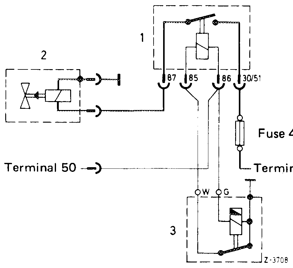
Wiring diagram of starting device with relay
1 Relay
2 Starting valve 3 Thermo-time switch
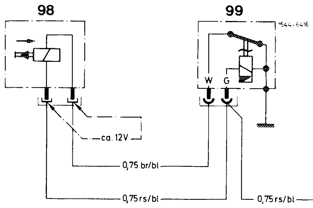
Wiring diagram of staring device without relay starting September 1975 98 Cold starting valve 99 Thermo-time switch c To terminal 50
Offset of release contacts in ignition distributor
Connect control unit, run engine at approx. 2000/min. Actuate:
Offset of release contacts in ignition distributor. Measure:
Connection electronic control 1. Terminal 12 and terminal 21 2. Terminal 12 and terminal 22 unit multi-point contactor: 3. Terminal 12 and terminal 13 4. Terminal 12 and terminal 14
Pointer of voltmeter swings to a mean value. When changing connections, Nominal value: the deviation may amount to max 0.4 V of mean value.
Nominal value not attained.
Possible causes and remedy: If deviations are higher, renew release contact slide-in in ignition distributor.
C. With Bosch tester KD-JED 7500
The test jobs are shown in test list of unit.