Checking starting device
WIS 07.4-125
Test values
| oe Delivery pressure in ring line | Measuring point | in front of cold starting valve in ring line |
| bar gauge pressure | 2.0+ 0.1 | |
| Battery voltages | ||
| Rest potential | 12.2 volts | |
| Starting voltage | 10 volts | |
| Alternator regulating voltage Voltages at ignition coil | 13.9–14.8 volts with contact regulator 13.7–14.5 volts with transistorized regulator | |
| Voltage at terminal 15 | approx. 4.5 volts | |
| Voltage at terminal 1 | 0.5–2.0 volts | |
| Series resistance bridge (when starting) | 10 volts |
Conventional tools
Voltmeter and ohmmeter
Revolution counter
Pressure gauge with calibrated measuring range from O—2.5 bar gauge pressure
1 Check battery for external condition (visual checkup).
Pay attention to contamination, in particular to battery pole oxidation.
2 Test battery voltages.
Note: During checkups a) and b), the voltmeter connection remains unchanged.
a) Rest potential
Connect voltmeter to battery at correct polarity and read voltage. Nominal value 12.2 volts.
b) Starting voltage
Pull cable 4 from ignition coil. Actuate starter for a short moment while reading voltage. Nominal value 10 volts. If the nominal value is not attained, check battery, charge or renew, if required.
c) Alternator regulating voltage
Connect voltmeter to alternator B +. Return cable 4 to ignition coil. Start engine, increase speed to 2000/ min and keep constant. Load alternator by switchingon dimmer, fog lamp and windshield wiper.
Read regulating voltage within 30 seconds. Nominal value 13.9–14.8 volts with contact regulator or 13.7–14.5 volts with transistorized regulator. If the nominal value is not attained, check alternator and regulator and renew, if required.
3 Check voltage at terminal 15 of ignition coil. For this purpose, disconnect plus cable of voltmeter from battery and connect to terminal 15 of ignition coil.
Switch-on ignition and read voltage, nominal value approx. 4.5 volts.
Check voltage at terminal 1 of ignition coil. For this purpose, disconnect plus cable of voltmeter from terminal 15 and connect to terminal 1 of ignition coil. Switch-on ignition and read voltage. Nominal value 0.5–2.0 volts.
4 Check series resistance bridge while starting engine and read voltage during starting sequence. Nominal value 10 volts.
Checking fuel pressure in ring line
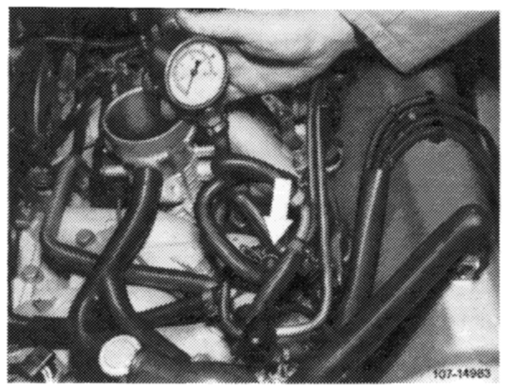
5 Connect pressure gauge in front of cold starting valve to ring line. For this purpose, reduce fuel pressure for safety reasons. Pull electric plug from cold starting valve. Connect cold starting valve with separate cable to B+ and ground for approx. 20 seconds.
Then return plug connection to cold starting valve.
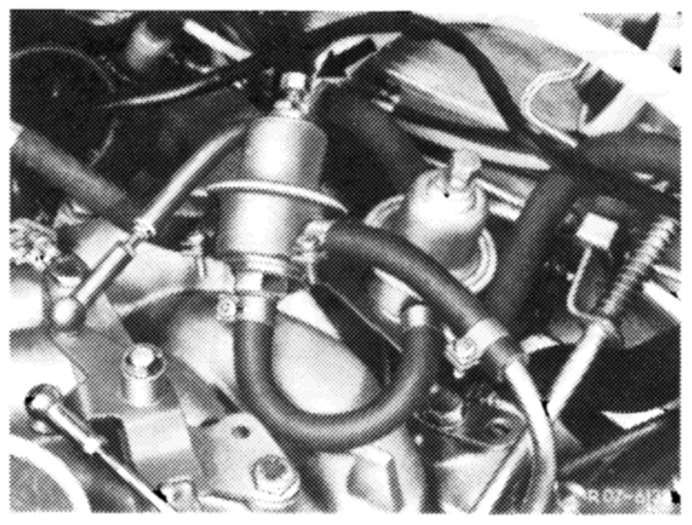
6 Switch ignition on and off several times to establish fuel pressure.
7 Read fuel pressure.
Nominal value = 2.0 + 0.1 bar gauge pressure.
Adjust by means of adjusting screw (arrow) on pressure regulator, if required.
Checking cold starting valve for function and leaks
8 Remove cold starting valve with fuel hose connected and hold into a container.
15/54
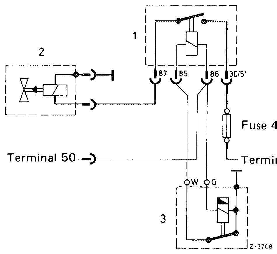
Circuit diagrm of starting device with relay
1 Relay
2 Starting valve 3 Thermo-time switch
Checking function
9 Switch-on ignition.
10 Connect cold starting valve with separate cable to B+ and ground. Cold starting valve should eject in cone shape.
Attention! Connect cable first to cold starting valve to avoid sparking. No separate cable is required below +35°C, attach cable plug instead.
Checking for leaks
11 Release separate cable connection on cold starting valve. Dry cold starting valve at nozzle. No drops should show up.
12 Switch off ignition.
13 Mount cold starting valve with new seal.
14 Return cable plug to cold starting valve.
Checking thermo-time switch
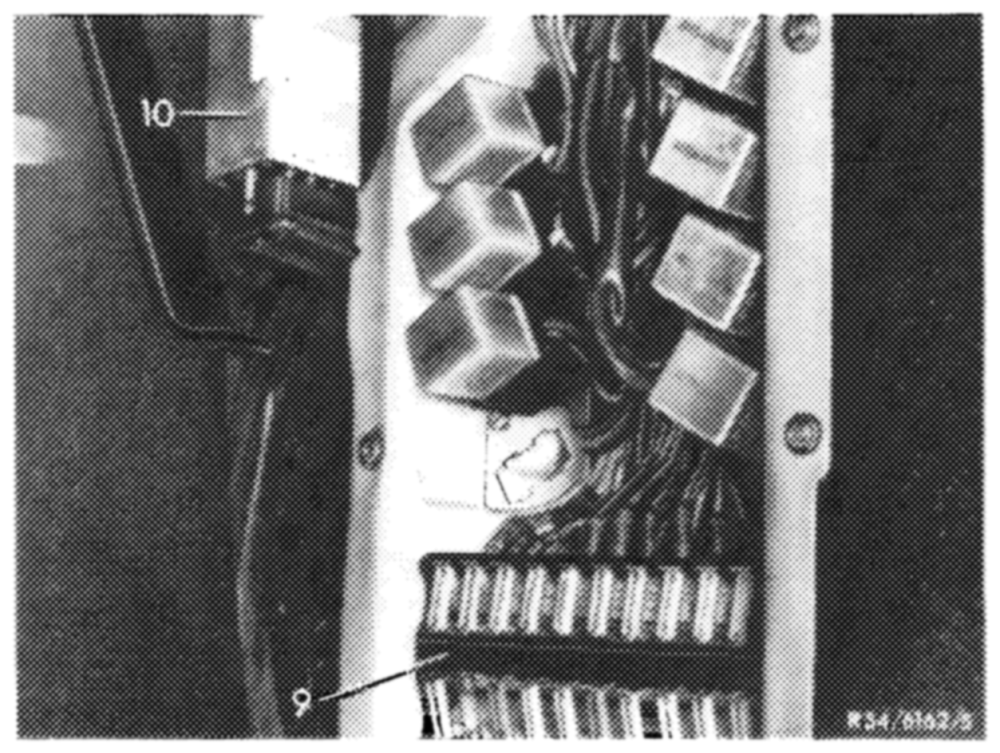
The cold starting valve is actuated only at coolant temperatures below +35°C by means of closed thermotime switch via relay (9).
The actuating time increases with decreasing temperature and attains approx. 12 seconds at — 20°C.
Relay layout model 107
Code number 1 Relay fuel pump Code number 2 Relay cold starting valve Code number 3 Relay electronic injection system Code number 4 Relay starter/air conditioner Code number 5 Relay changeover valve ignition (19) Code number 8 Relay separation temperature switch 62°C from 100°C
9 Relay exhaust gas return flow/advance Code number 1 ignition (58)
9 Fuses
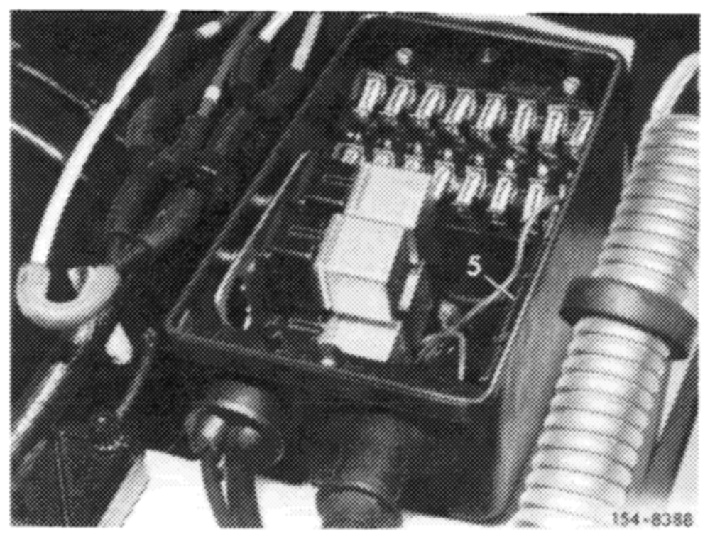
10 Time switch heated rear window
Relay layout model 116
Code number 1 Relay fuel pump Code number 2 Relay cold starting valve
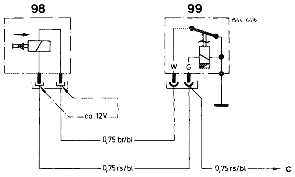
Note: Starting approx. September 1975 the relay (9) for cold starting valve is no longer installed. The cold starting valve is directly contacted by thermo-time switch (refer to circuit diagram).
Circuit diagram of starting device without relay starting September 1975
98 Cold starting valve 99 Thermo-time switch c To terminal 50
Testing below + 35°C coolant temperature
15 Connect voltmeter to connection of cold starting valve.
16 Actuate starter. Voltmeter should then indicate 10 volts for a given time (depending on coolant temperature) .
The switching time increases with decreasing temperature by approx. 1 second per 5°C,
e.g. +35°C = O seconds +20°C = 3 seconds
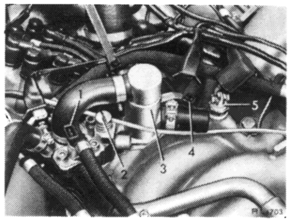
During this test, it is recommended to check thermotime switch (5) also with an ohmmeter.
Test value below +35° C:
Connection G-ground = approx. 20 ohms Connection W-ground = approx. O ohm (contacts in switch closed).
4 Cooling water temperature sensor 5 Thermo-time switch
Testing above +35°C coolant temperature
17 Above +35°C coolant temperature the thermotime switch can be tested with an ohmmeter only. For this purpose, pull plug from thermo-time switch.
Test values above +35°C:
Connection G-ground = approx. 60 ohms Connection W-ground= approx. 100 ohms (contacts in switch opened).
Return plug.
Checking switch-off point of supplementary air valve
18 Pull contour hose from supplementary air valve. At approx. 70°C coolant temperature, the supplementary air valve should switch off (no more suction).
19 Check air and coolant temperature sensors in installed condition.
a) Without ohmmeter
Pull-off cable plugs one after the other, start engine and pay attention to speed change.
b) With ohmmeter
Pull-off connection cable and check resistance with ohmmeter.
Nominal values:
Air temperature sensor = 6402 at O0°C = 400 2 at 10°C = 300 2 at 20°C = 210 2 at 30°C = 150 Q at 40°C
Coolant temperature sensor=5.9k2 at O°C =2.5kQ at 20°C =1.2kQ at 40°C =600 2 at 60°C = 325 Q at 80°C = 190 2 at 100°C