Operation
WIS 07.6-050
Federal and California version model year 1977/78
A. General
Information plate

Federal version basic color black California version basic color yellow Federal version high altitudes basic color red
Identification of vacuum lines
The basic color of vacuum lines for emission control Lines originating at a vacuum source (suction lines) system is transparent (white). have only one color stripe.
Additional color stripes are used to facilitate Lines terminating at a vacuum-operated device identification of the individual functions. (operating lines) have two color stripes. Purple is always the second color.
| Emission control system | Color coding of originating vacuum line | Color coding of terminating vacuum line |
| Ignition Advance Retard EGR Air injection | red yellow brown blue | _ _ brown/purple blue/purple |
07.6.3–050/1 USA 1977/78
Recognizing catalyst from color of information plate — basic color/lettering
| _—_‘ Federal version California version | Federal version high altitudes | Federal version tourist vehicles | California version tourist vehicles |
| green/silver black/silver black/silver | black/silver | red/silver | blue/silver red/silver |
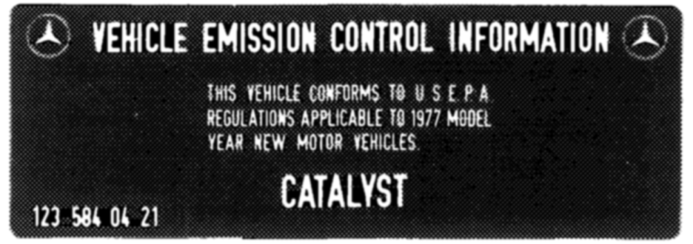
This vehicle is provided with catalyst.
Tourist vehicle
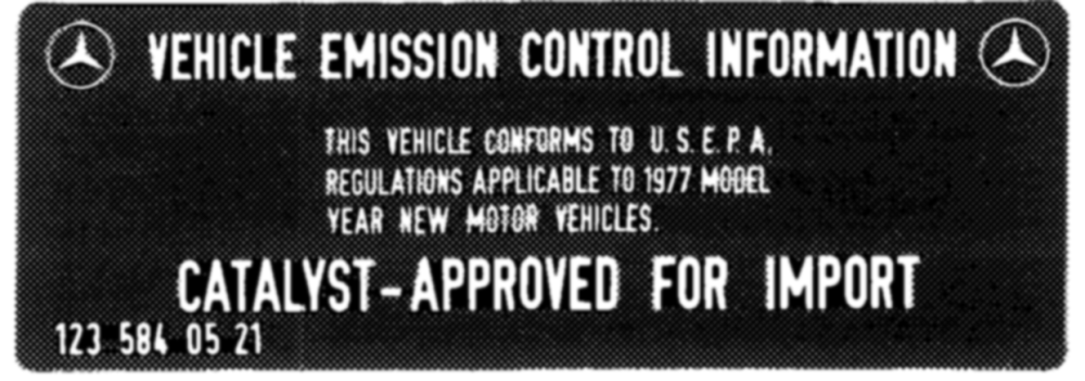
This vehicle is not provided with catalyst by manufacturer.
Catalyst must be installed prior to import into USA.
B. EGR (exhaust gas recirculation)
To reduce nitrogen oxides in exhaust gases, the portion of the gases from the exhaust manifold is returned to the intake pipe by means of a valve.
The quantity of the returned exhaust gas is controlled and in some driving conditions shut off, so that the respective driving characteristics will not be influenced.
Function diagram
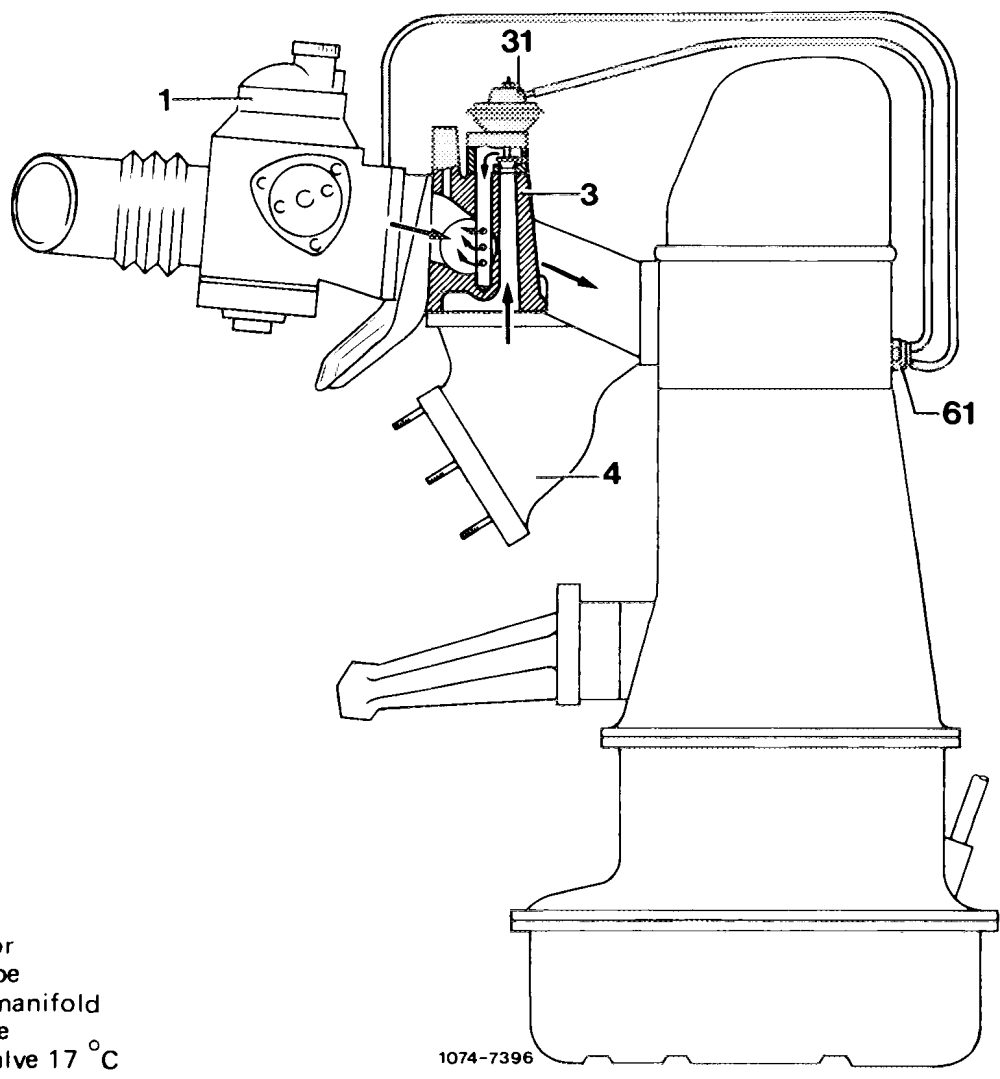
1 Carburetor 3. Intake pipe 4 Exhaust 1 EGR valve 1 Thermovatve
EGR components:
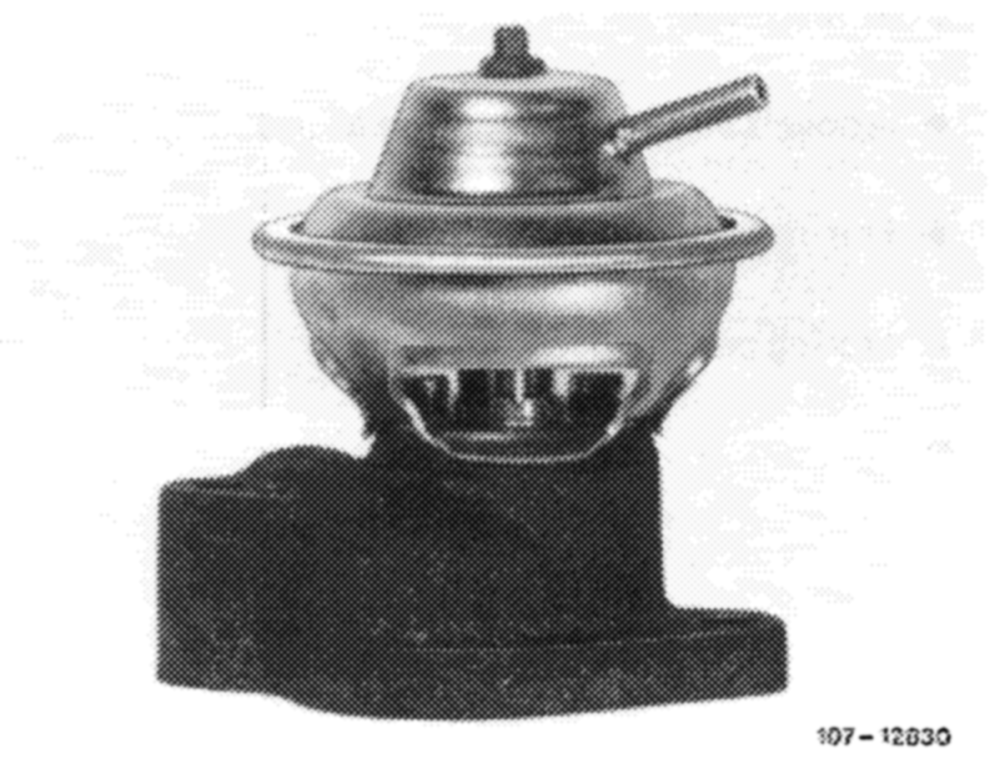
EGR valve
The EGR valve is attached to intake pipe and controls the quantity of the recirculated exhaust gases, in dependence of the coolant temperature and the vacuum.
07.6.3-050/2 USA 1977/78
Thermovalve 17 °C (color code blue)
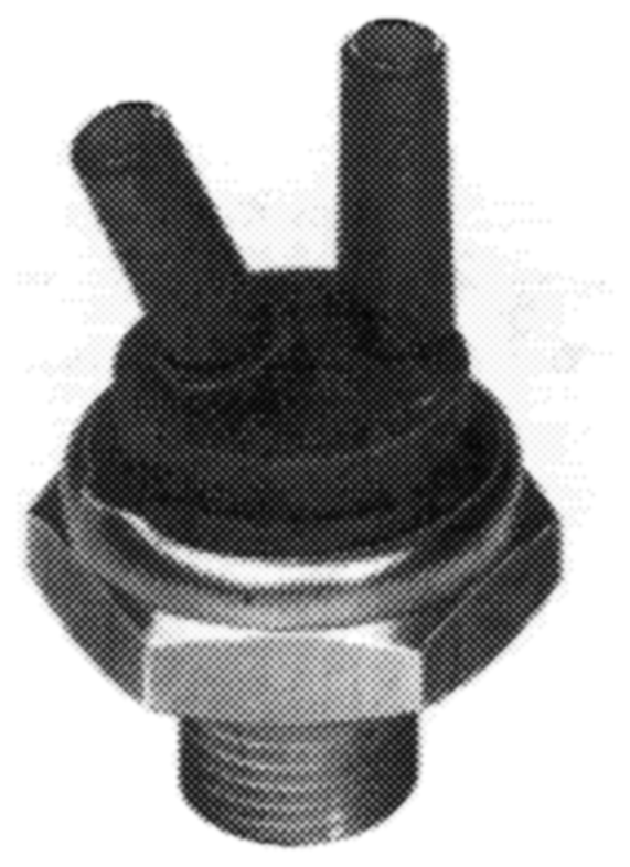
The thermovalve is screwed into cylinder head and opens at approx. 17 °C coolant temperature.
Below 17 °C coolant temperature the bimetallic plate is located at the O-ring and closes connection “BM,
As from 17 °C coolant temperature the bimetallic plate will snap down under influence of heat. Both connections are connected to each other.
10710895
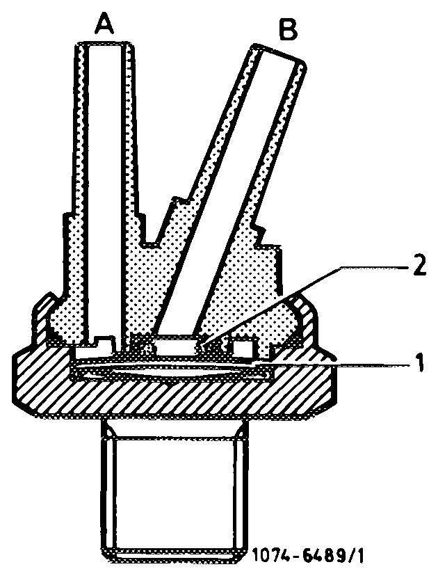
The vacuum line to intake pipe should be plugged to connection ‘’B”, since this alone will guarantee absolute tightness between bimetallic plate and O-ring.
OpnBimetallic plate O-ring To vacuum switch To intake pipe
Intake pipe
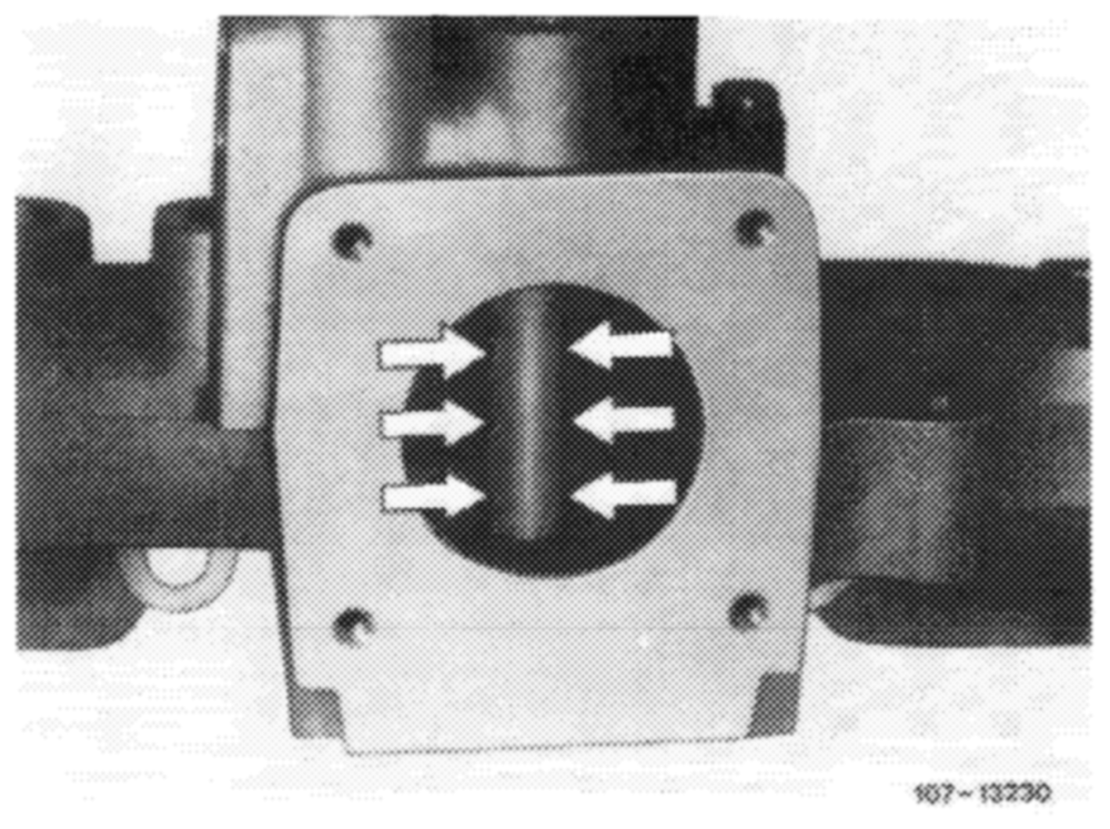
Inside intake pipe is a pipe with lateral bores (arrows).
These bores distribute the recirculated exhaust gases to the drawn-in fuel-air mixture.
EGR is activated:
@ Above 17 °C coolant temperature.
@ During acceleration.
@ During partial load operation.
@ During transition to deceleration (coasting).
07.6.3—-050/3 USA 1977/78
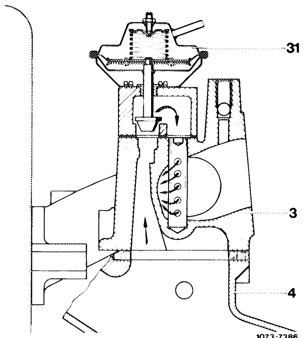
Starting at a coolant temperature of approx. 17 °C in cylinder head, during partial load operation and during acceleration, a portion of the exhaust gases is recirculated into the combustion chamber. The additon of exhaust gases to the fuel-air mixture also reduces the generation of nitric oxides. The quantity of the recirculated exhaust gases depends on the throttle valve position (vacuum at throttle valve of carburetor).
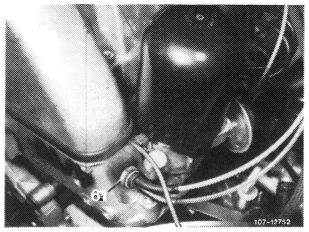
A tube with lateral outlet bores vertically located in intake pipe serves to distribute the exhaust gases uniformly to the drawn-in fuel-air mixture.
Depending on throttle valve position, the EGR valve in cylinder head is more or less supplied with exhaust gases via thermovalve 17 °C (61) in cylinder head.
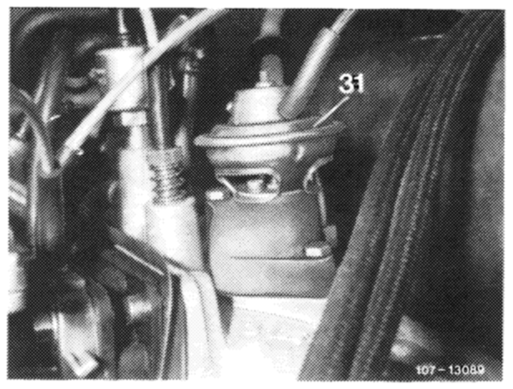
The EGR valve (31) attached to intake pipe opens and permits exhaust gases to flow to intake pipe by way of a duct from exhaust manifold.
07.6.3–050/4 USA 1977/78
C. Air injection
Federal and California version.
To reduce the incompletely burnt components in the exhaust gases, air is injected into hot zone behind exhaust valves or in catalyst.
Afterburning is controlled by way of the engine temperature and vacuum conditions in intake pipe.
To avoid backfiring in exhaust, as well as overheating of catalyst, the air injection is shut off in given driving ranges,
Function diagram
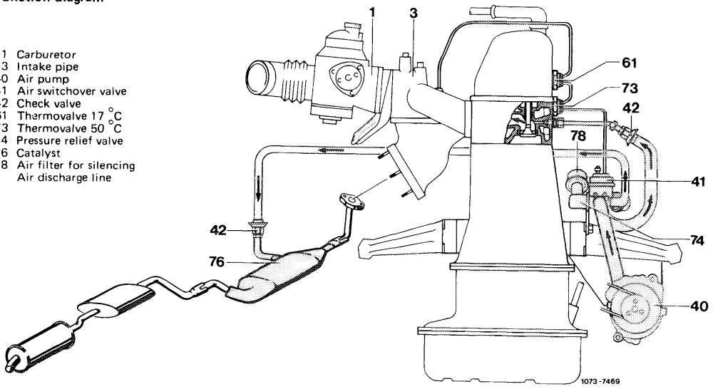
40 41 42 61
74 76 78 a
Components of air injection:
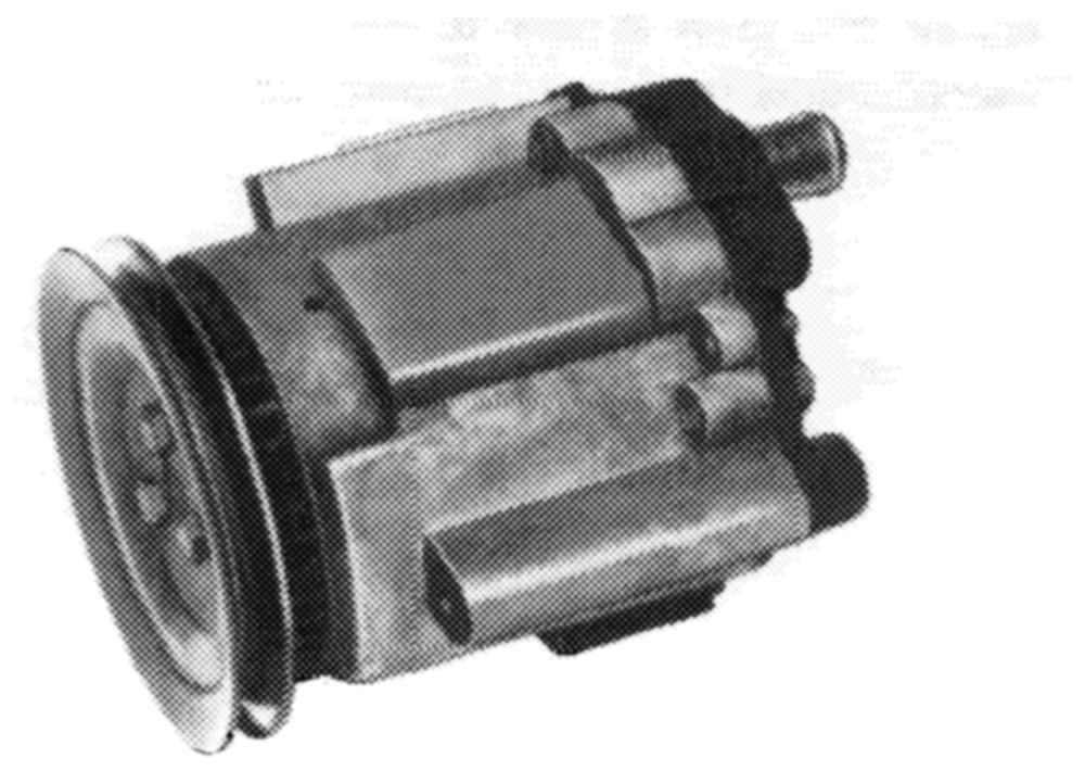
Air pump (Saginaw pump)
The air pump is an impeller pump with maintenancefree centrifugal filter which cleans the drawn-in air.
107+3959/1
07.6.3–050/5 USA 1977/78
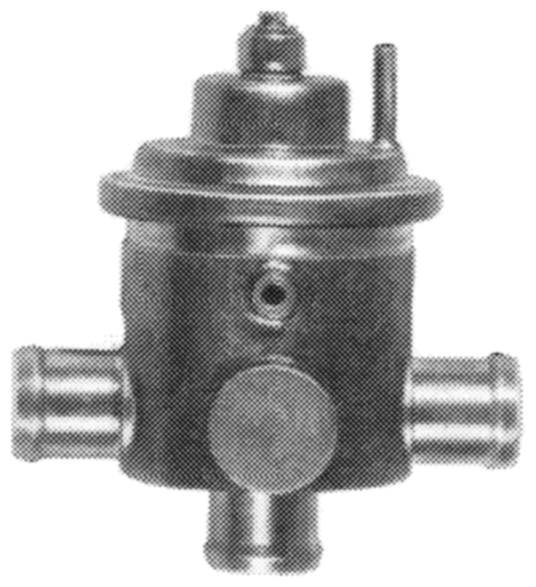
Air switchover valve (anti-backfire valve)
The air switchover valve serves the purpose of controlling the air injection in dependence of operating condition of engine.
The housing cover is provided with a vent valve.
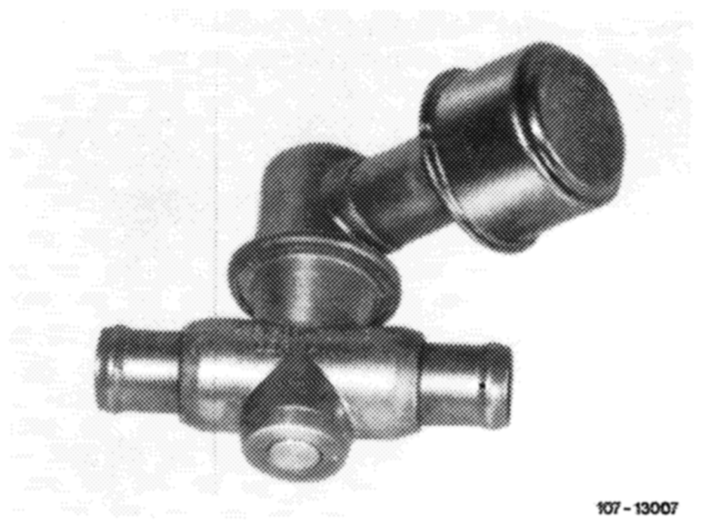
107~ 9139
Pressure relief valve
The excess air delivered by the air pump at high engine speeds is discharged into the atmosphere by the pressure relief valve starting at a line backpressure of approx. 0.3 bar gauge pressure. For silencing, the pressure relief valve is provided with an air filter (muffler).
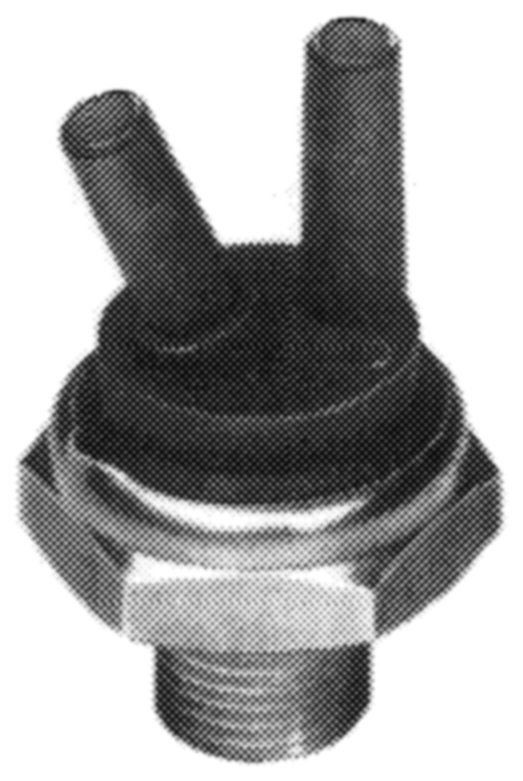
Thermovalve 17 °C (color code blue)
The thermovalve is screwed into cylinder head and ° opens at approx. 17 C coolant temperature. Below 17 °C coolant temperature the bimetallic plate rests against O-ring and closes connection B”.
Above 17 °C coolant temperature, the bimetallic plate snaps downward under influence of heat. Both connections are connected to each other.
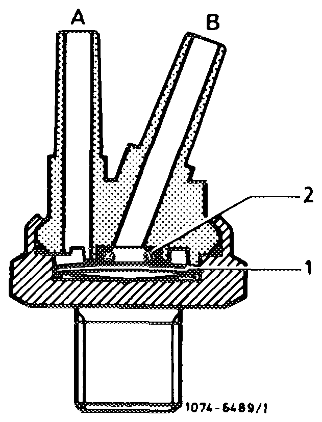
The vacuum line to intake pipe should be plugged to connection ’B”’, since this alone guarantees perfect sealing between bimetallic plate an O-ring.
1 Bimetailic plate 2 O-ring
07.6.3-050/6 USA 1977/78
Thermovalve 50 °C (color code black with green dot,
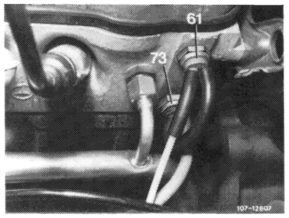
introduced during model year 1978 color code green)
The thermovalve (73) is also screwed into cylinder head and closes at a coolant temperature of approx. 50 °C.
Below 50 °C coolant temperature the vacuum of primary thermovalve 17 °C (61) can act directly on air switchover valve (41) via thermovalve 50 °C (73).
Above approx. 50 °C coolant temperature the heated bimetallic plate will snap over and the connection to thermovalve 17 °C (61) is closed.
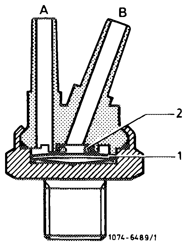
The vacuum hose of thermovalve 17 °C (61) should always be plugged to diagonal connection (B), since this alone guarantees perfect sealing with the valve closed.
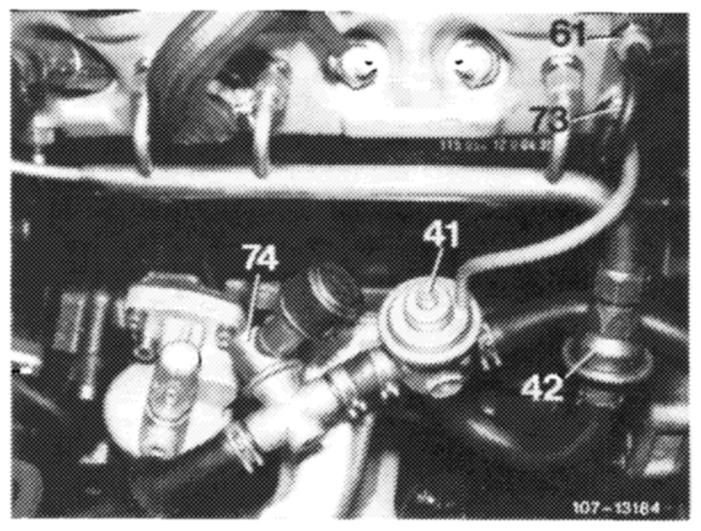
Air injection lines
a) For air injection into cylinder head a line with four connections, i.e. one for each cylinder, is installed.
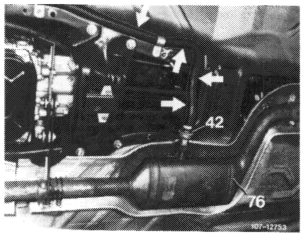
b) For air injection into underfloor catalyst an air line is installed underneath vehicle (arrows).
07.6.3-050/7 USA 1977/78
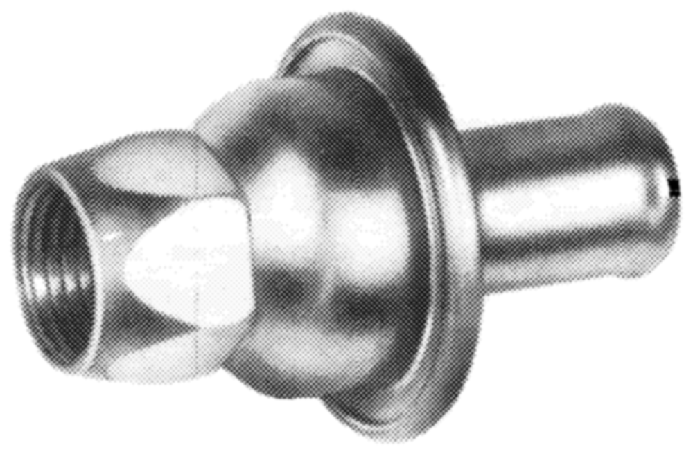
Check valves
The check valves prevent the inflow of hot exhaust gases into air injection lines.
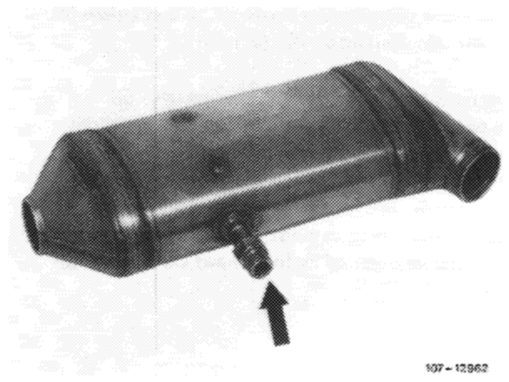
Catalyst
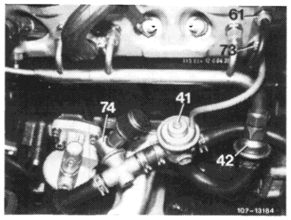
The catalyst is designed as an underfloor catalyst and is located in exhaust system in front of mufflers.
The air pump driven by the crankshaft and a V-belt delivers continuously air when the engine is running.
The air flows to pressure relief valve (74), which discharges the excess air delivered at high engine speeds into the atmosphere at a backpressure of approx. 0.3 bar.
The pressure relief valve (74) delivers the air through air switchover valve (41) either into the injection ducts in cylinder head or into catalyst.
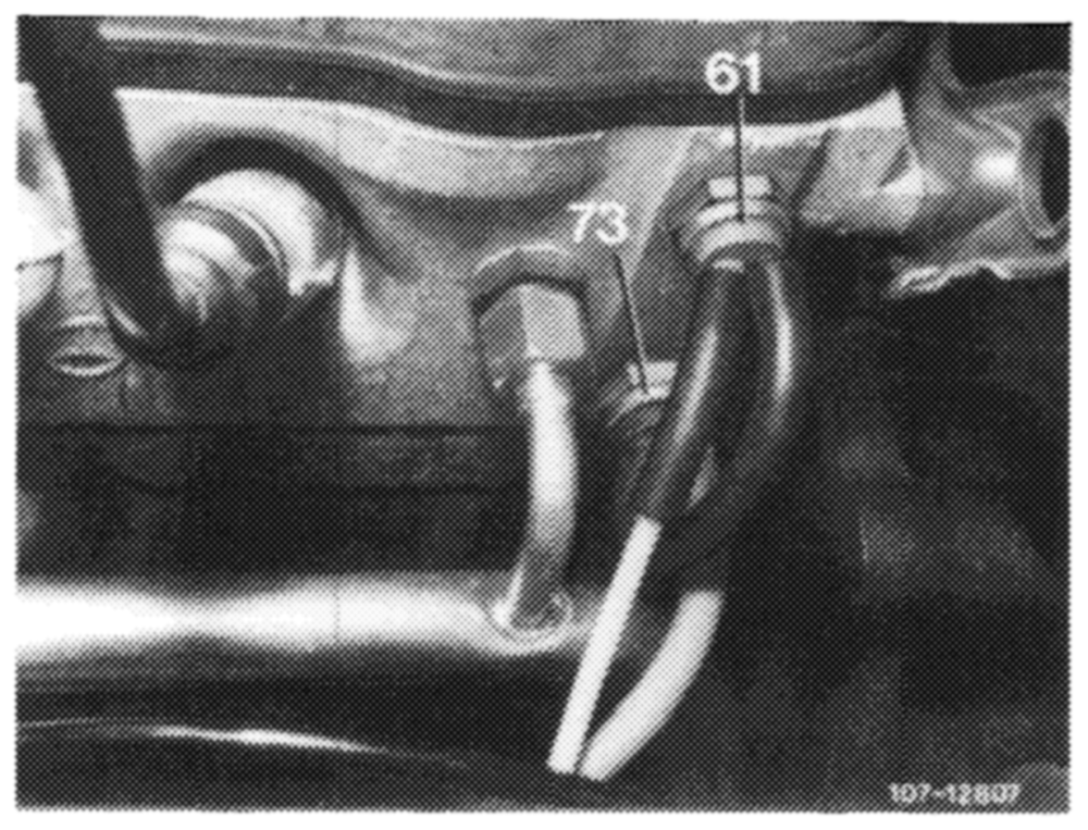
The air switchover is controlled by the air switchover valve via thermovalve 17 °C (61) and 50 °C (73).
07.6.3-050/8 USA 1977/78
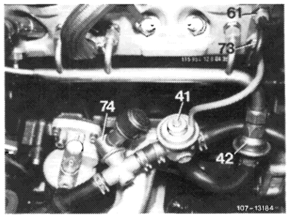
There are three temperature ranges:
1. Coolant temperature below 17 °c
(Air injection into catalyst)
Thermovalve 17 °C (61) is closed, thermovalve 50 °C (73) is open. No vacuum flows to diaphragm of air switchover valve (41), the diaphragm is connected to atmosphere by the vent cap on valve. The compression spring in air switchover valve closes the injection line to cylinder head. The delivered air is blown into catalyst. This will prevent overheating of catalyst in warming-up phase.
2. Coolant temperature above 17 °C and below 50 °C
(Air injection into cylinder head)
Thermovalve 17 °C (61) and thermovalve 50 °C (73) are open. The vacuum from intake pipe arrives at diaphragm of air switchover valve (41) and the diaphragm is pushed in upward direction against the spring force. The injection line to cylinder head is opened, the line to catalyst is closed. The air is blown into exhaust ducts of cylinder head via check valve (42).
3. Coolant temperature above 50 °C
(Air injection into catalyst)
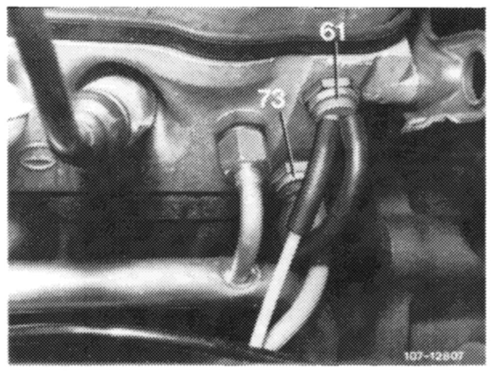
Thermovalve 17 °C (61) is open, thermovalve 50 °C (73) is closed. No more vacuum arrives at diaphragm of air switchover valve. The diaphragm chamber is connected to atmosphere via vent cap on valve.
07.6.3–050/9 USA 1977/78
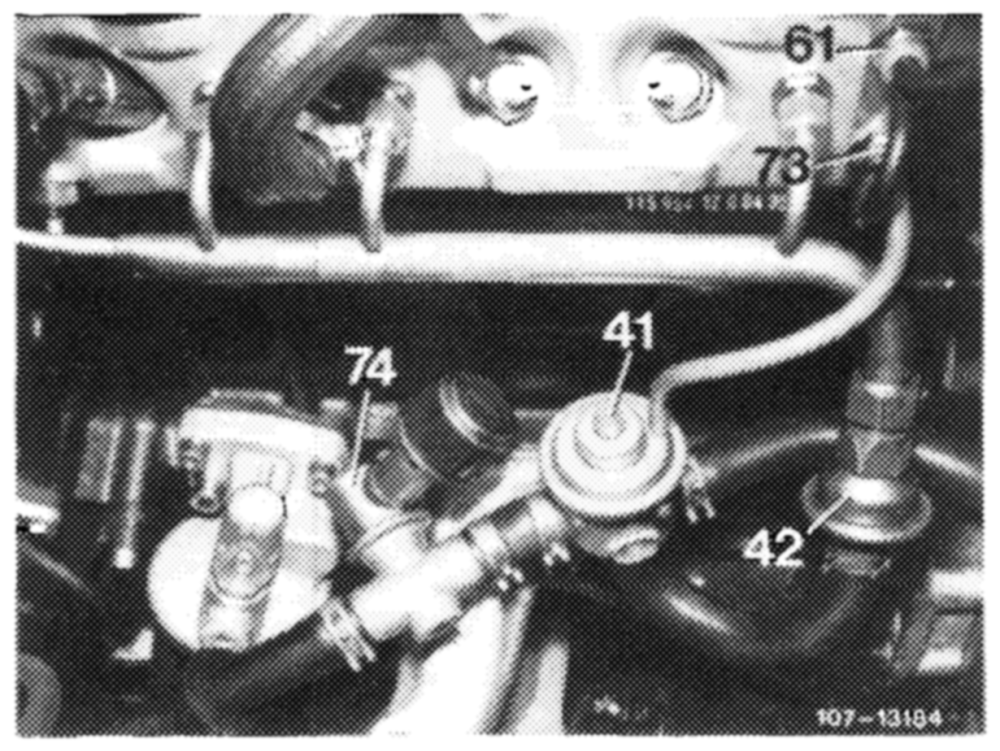
The compression spring in air switchover valve closes the injection line to cylinder head. The supplied air is injected into catalyst via check valve (42).
The oxygen in the injected air mixes with the hot exhaust gases and reacts in catalyst.
D. Catalyst
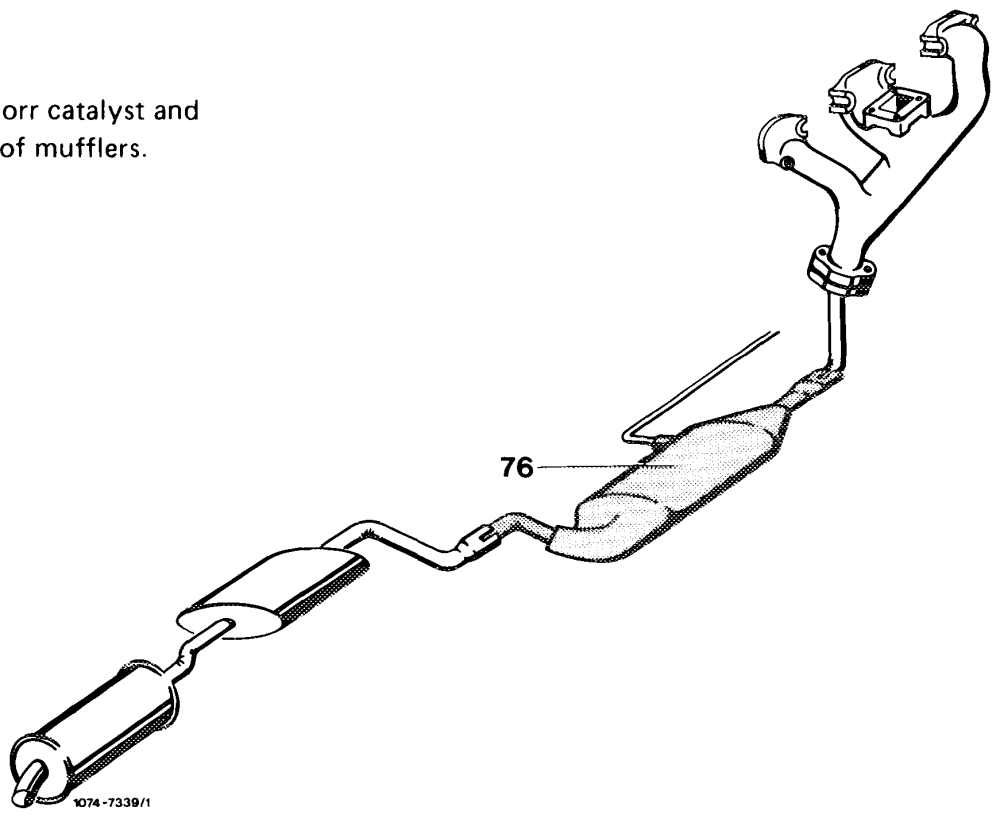
The catalyst is designed as an underflorr is located in exhaust system in front
07.6.3–050/10 USA 1977/78
The catalyst is designed as a double bed catalyst, i.e. the housing contains two monolyths, a slim one in front and a wide one behind.
The monolyths (3) are oval, honeycomb-shaped bodies of ceramic material, which are elastically mounted in wire netting (2) inside catalyst housing. The noble metal evaporated on the monolyths, the actual catalyst, accelerates the oxidation of CO and hydrocarbons at the respective temperature with the addition of fresh air.
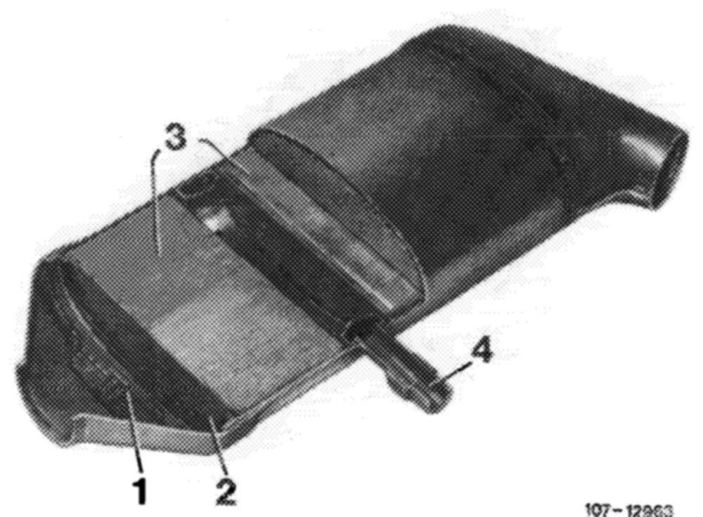
The air is injected into catalyst behind the small monolyth above annular duct (4).
Distribution plate PWN Wire netting Monolyths Annular duct
To keep catalyst in operating condition, run engine with unleaded fuel only.
Preventing overheating of catalyst
Extended overheating of catalyst will lead to catalyst damage, i.e. the monolyths in catalyst may melt.
The catalyst may overheat, if:
a) The specified engine service is not maintained.
Perfect spark plugs are important for life of catalyst.
b) Irregular operation of engine results in excessive enrichment of fuel-air mixture.
c) The emission control system is arbitrarily changed.
07.6.3–050/11 USA 1977/78
E. Air injection tourist vehicles
Federal and California version model year 1977/78
Tourist vehicles are supplied ex factory without a catalyst.
To reduce the incompletely burnt components in exhaust gas, air is injected into hot zone behind exhaust valves.
Afterburning is controlled via the engine temperature and vacuum conditions in intake pipe.
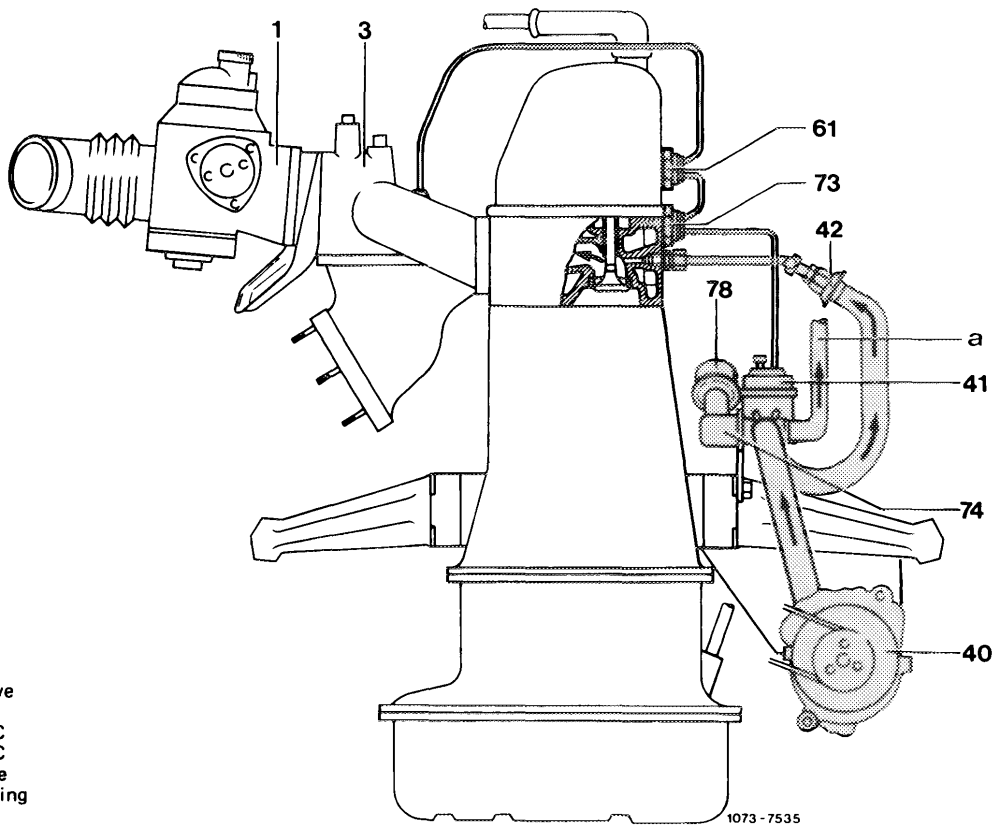
To prevent backfiring in exhaust, the air injection is shut off in given driving ranges.
Function diagram
1 Carburetor
2 Intake pipe
40 Air pump
41 Air switchover valve
42 Check valve °
61 Thermovaive 17 ,C
73 Thermovalve 50 C
74 Pressure relief valve
78 Air filter for silencing a Air discharge line
Components of air injection system:
Except for catalyst, components are similar to Federal and California version.
07.6.3-050/12 USA 1977/78
The air pump driven by crankshaft by means of a Vbelt delivers continuously air while the engine is running.
The air flows to pressure relief valve (74), which discharges excessive air delivered during high engine speeds into the atmosphere at a back-pressure of approx. 0.3 bar.
The pressure relief valve (74) guides the air by way of air switchover valve (41) either into the injection ducts in cylinder head or into the open air (atmosphere).
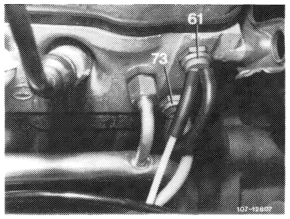
The air switchover procedure is controlled by the air switchover valve via thermovalves 17 °C (61) and 50 °C (73).
There are three temperature ranges:
1. Coolant temperature below 17 °C
(Air injection into the open air)
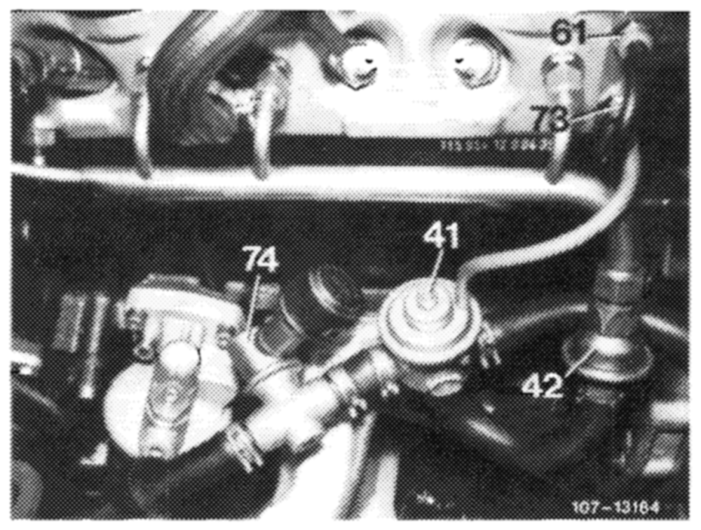
Thermovalve 17 °C (61) is closed, thermovalve 50 °C (73) is open. No vacuum flows to diaphragm of air switchover valve (41), the diaphragm is connected to atmosphere by the vent cap on valve. The compression spring in air switchover valve closes the injection line to cylinder head. The delivered air is blown into the open air.
2. Coolant temperature above 17 °C and below 50 °C
(Air injection into cylinder head)
Thermovalve 17 °C (61) and thermovalve 50 °C (73) are open. The vacuum from intake pipe arrives at diaphragm of air switchover valve (41) and the diaphragm is pushed in upward direction against the spring force. The injection line to cylinder head is opened and the line into the open air is closed. The air is blown into exhaust ducts of cylinder head via check valve (42).
3. Coolant temperature above 50 °C
(Air injection into the open air)
Thermovalve 17 °C (61) is open, thermovalve 50 °C (73) is closed. No more vacuum arrives at diaphragm of air switchover valve. The diaphragm chamber is connected to atmosphere via vent cap on valve. The compression spring in air switchover valve closes the injection line to cylinder head. The delivered air is blown into the atmosphere by way of the air discharge line.
07.6.3–050/13_ USA 1977/78
F. Fuel evaporation control system model year 1977
A fuel evaporation control system has been installed to improve emissions which are not directly connected with engine combustion.
Function diagram
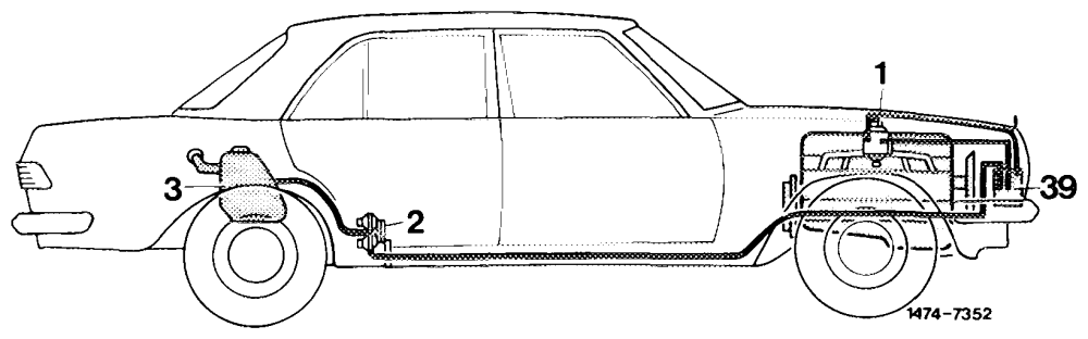
1 Carburetor with positive vent valve
2 Valve system
3 Fuel tank
39 Charcoal canister
Components of fuel evaporation control system:
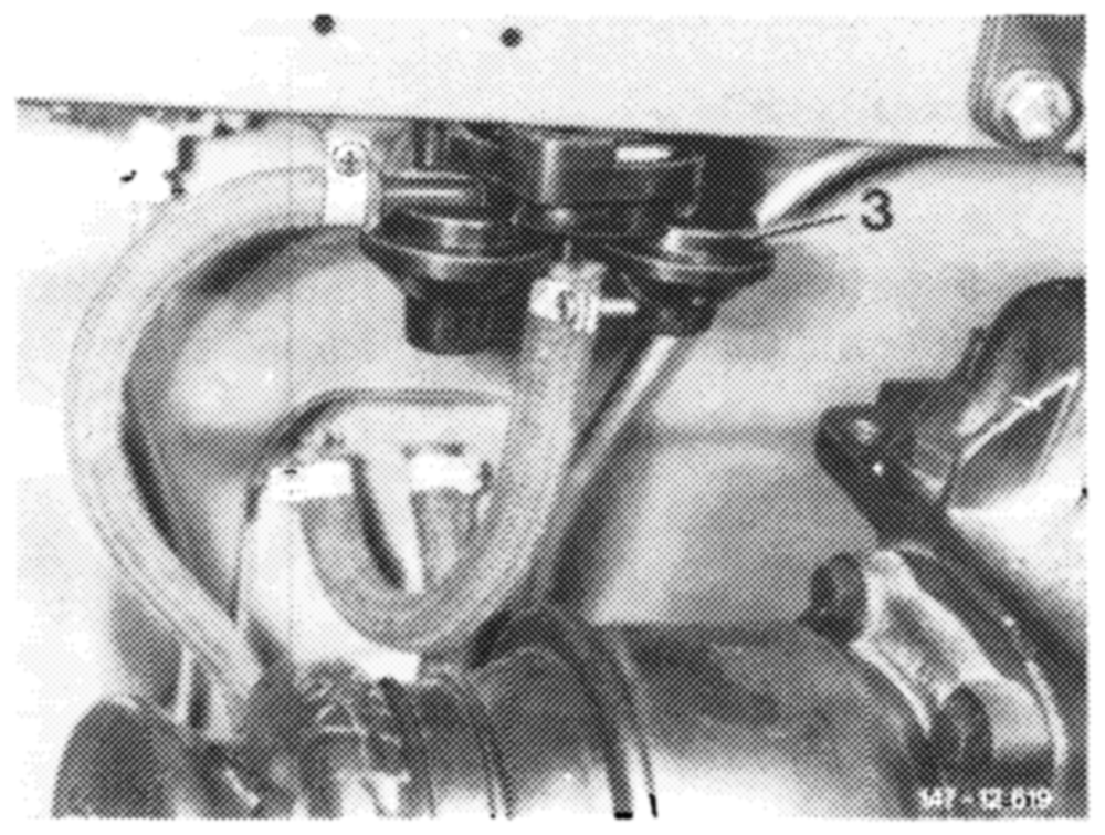
Valve system
The valve system is mounted underneath vehicle at level of rear legroom.
The valve system comprises three valves:
1. Negative vent valve 2. Pressure relief valve 3. Positive vent valve
The negative vent valve opens at a slight overpressure. The evaporation vapors are flowing via negative vent valve (1, direction B) into a line toward charcoal canister.
The pressure relief valve opens as a safety valve in the event of an overpressure in fuel evaporation control system. The fuel vapors are bled directly into the open air.
The positive vent valve opens whenever cooling down of fuel tank results in a vacuum.
07.6.3-050/14 USA 1977
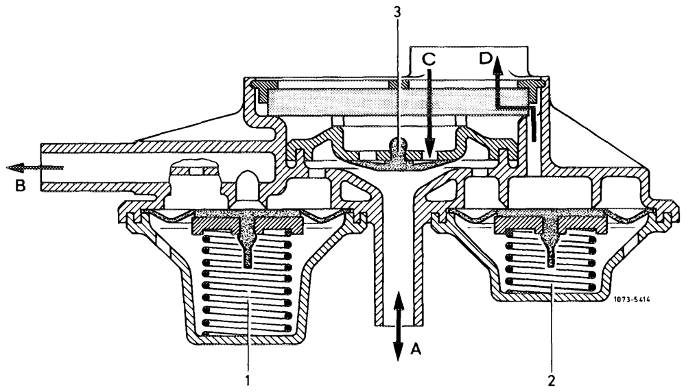
Negative vent valve DOMDPON= Pressure relief valve Positive vent valve To valve/to expansion tank To charcoal canister Fresh air input Output pressure relief valve
Charcoal canister
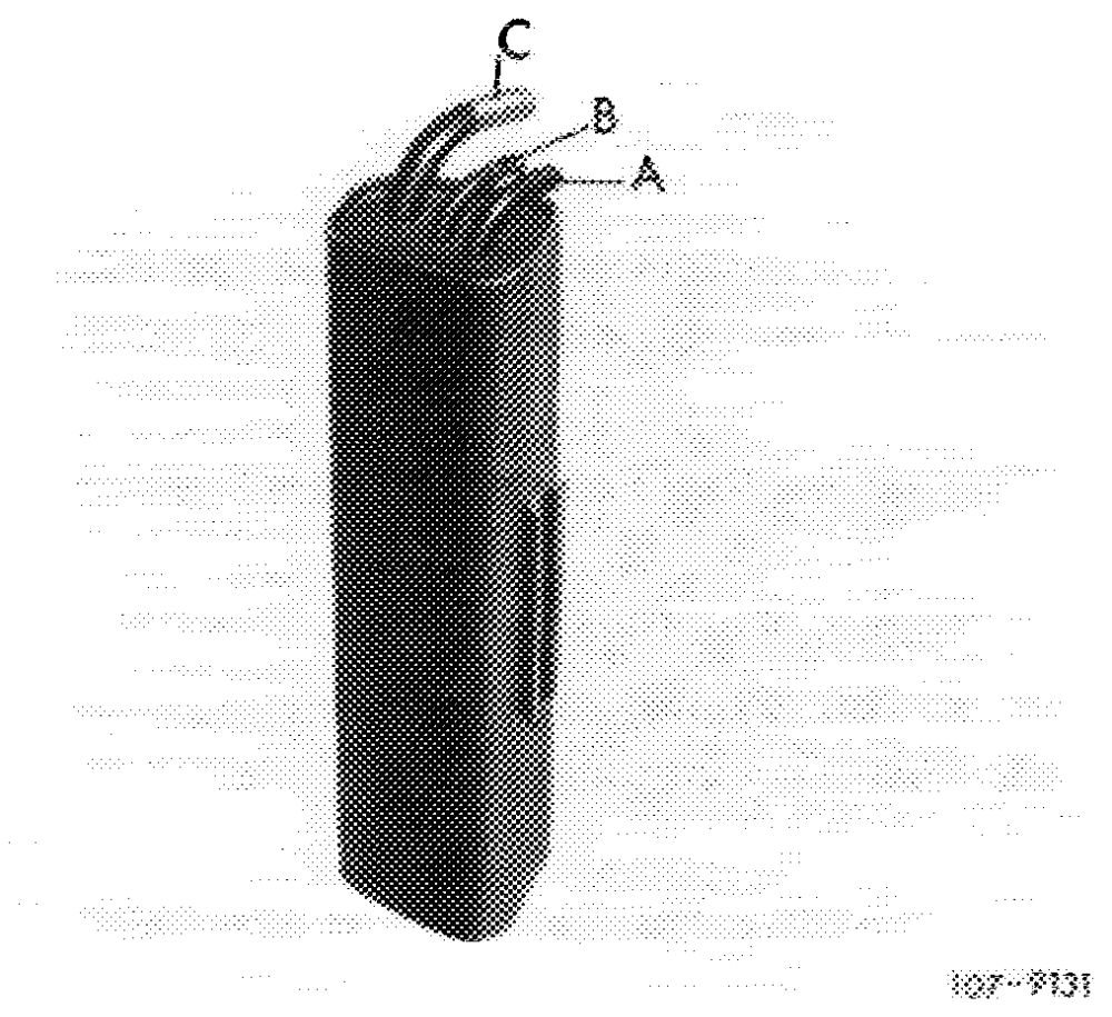
The fuel evaporation vapors from fuel tank, as well as those from float chamber, are stored in charcoal canister and are drawn again out of canister when driving.
A Connection tank vent B Draw-off connection C Connection float chamber vent valve
Float chamber vent valve
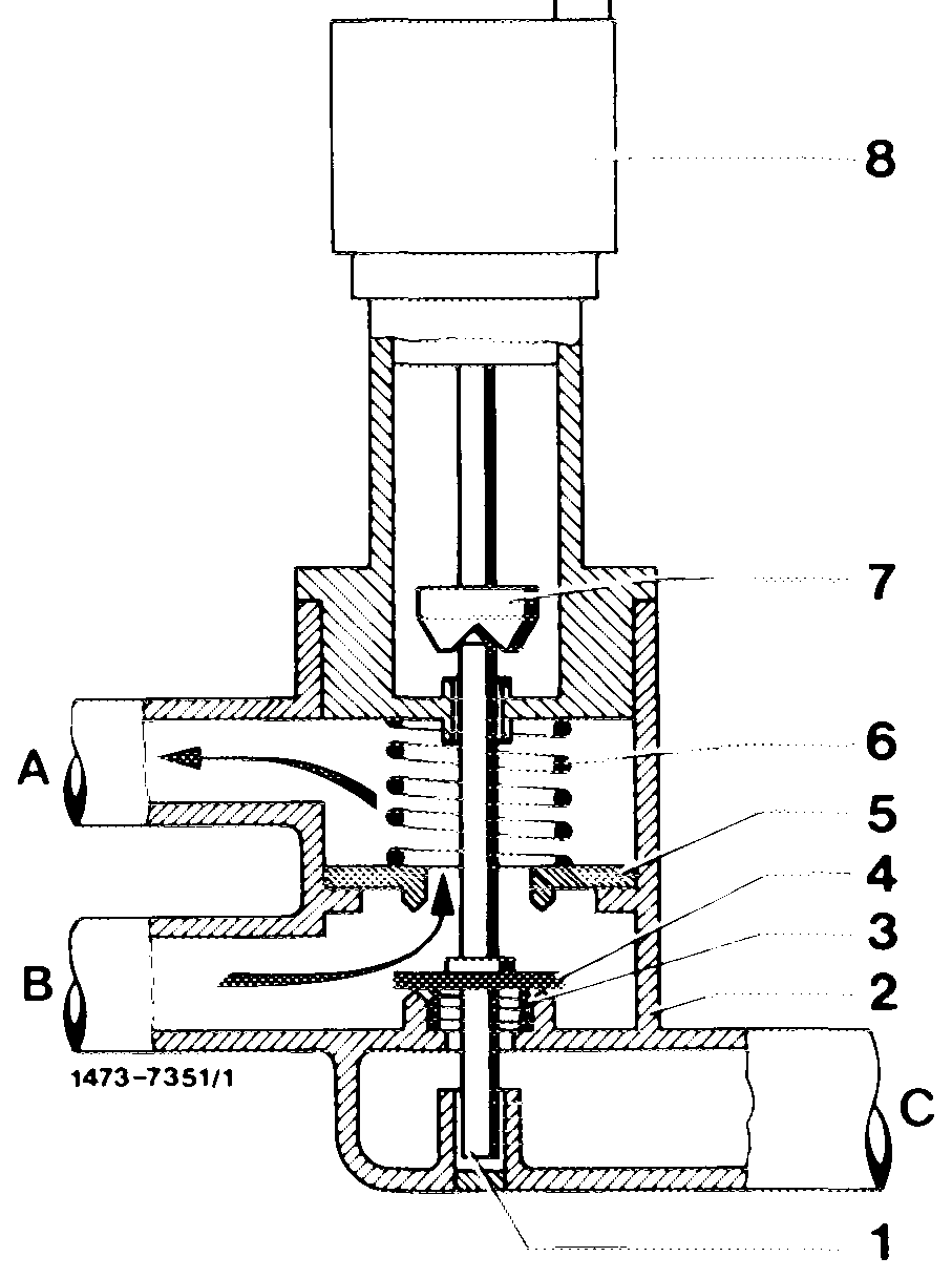
The carburetor is provided with an electromagnetic float chamber vent valve. The valve is actuated when the ignition is switched on or off.
07.6.3-050/15 USA 1977
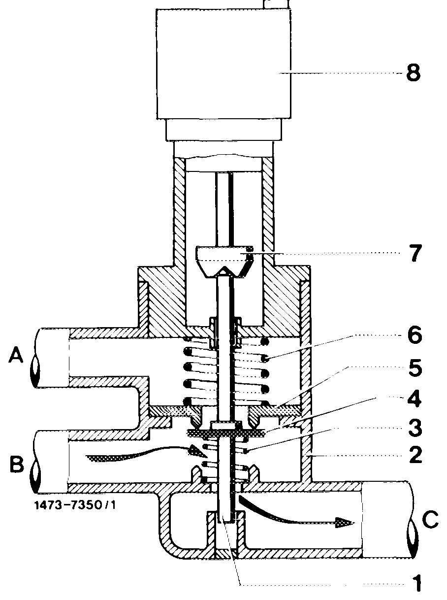
When the ignition is switched off, the solenoid of the ip valve is de-energized. Compression spring (3) presses the valve plate (4) against upper valve seat (5). The float chamber evaporation vapors are now flowing from bore B over valve seat through connection C to charcoal canister (external venting).
pb
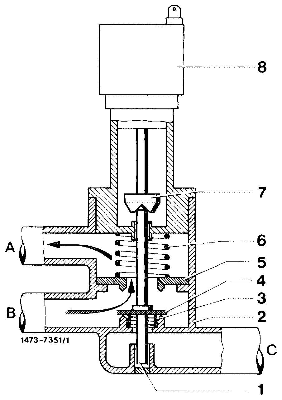
With the ignition switched on, the valve is energized. The solenoid (7) moves down and pushes the valve rod (1) in downward direction. Valve plate (4) closes connection C. The carburetor is switched to internal venting. The float chamber is now vented through bore A via valve through bore B.
Draw-off connection on carburetor
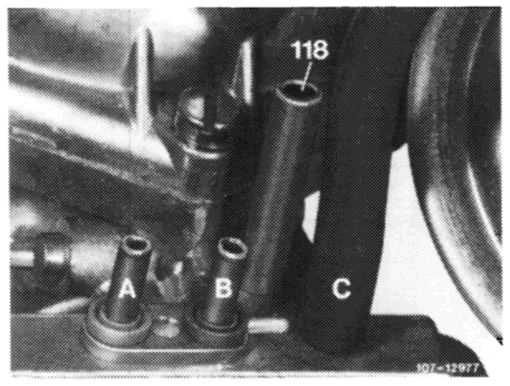
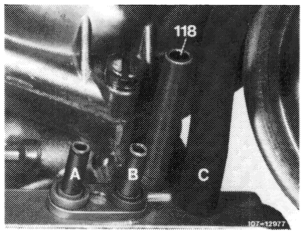
To draw fuel evaporation vapors from charcoal canister the carburetor is provided with a draw-off connection (118), which is provided with a vacuum in dependence of the throttle valve position.
07.6.3-050/16 USA 1977
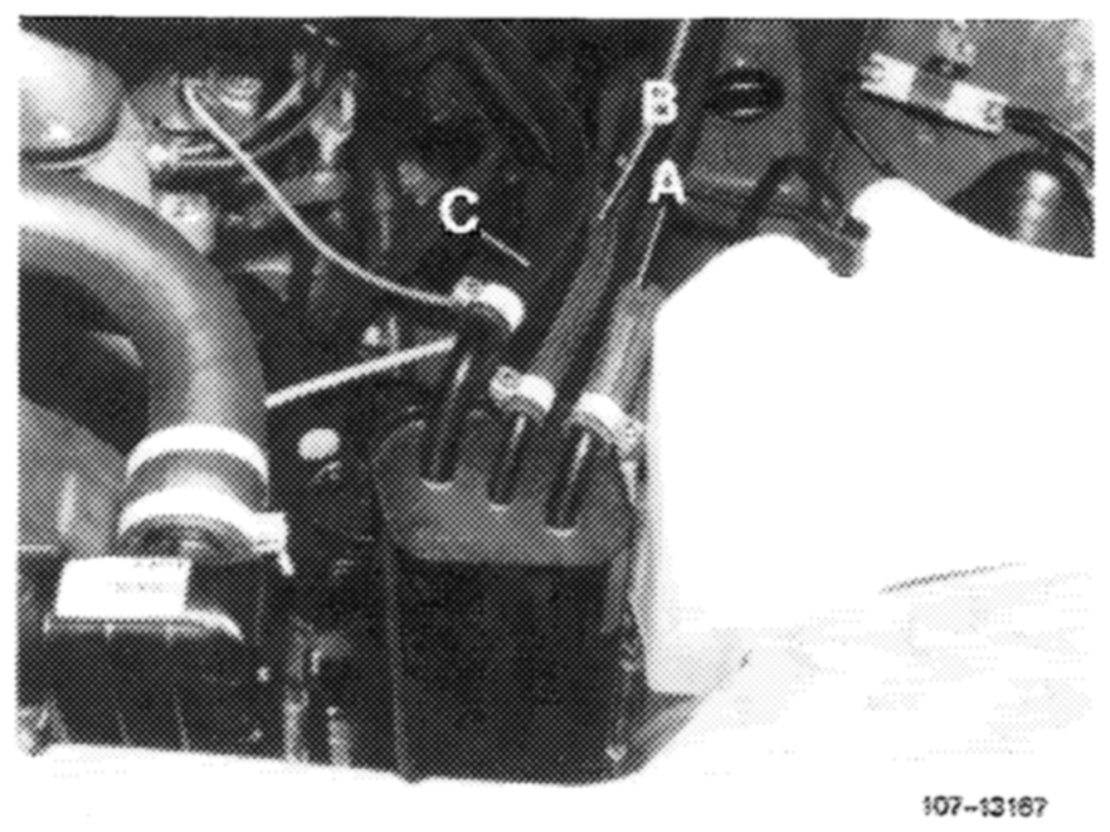
The fuel evaporation vapors from fuel tank are routed to charcoal canister (39) via valve system (2). The fuel evaporation vapors from the float chamber are also routed into charcoal canister via the float chamber vent valve with the engine stopped and the ignition switched off and are stored there. From charcoal canister (39) the fuel evaporation vapors are drawnoff via the draw-off connection (B) with the engine running and in dependence of the throttle valve position in carburetor.
A Connection tank vent B Draw-off connection C Connection float chamber vent valve
G. Fuel evaporation control system model year 1978
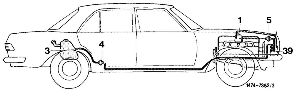
A fuel evaporation control system has been installed to improve emissions which are not directly connected with engine combustion.
1 Carburetor with positive vent vaive
3 Fuel tank
4 Vent valve unit
5 Regenerating valve
9 Charcoal canister
07.6.3–050/17 USA 1977/78
Vent valve unit
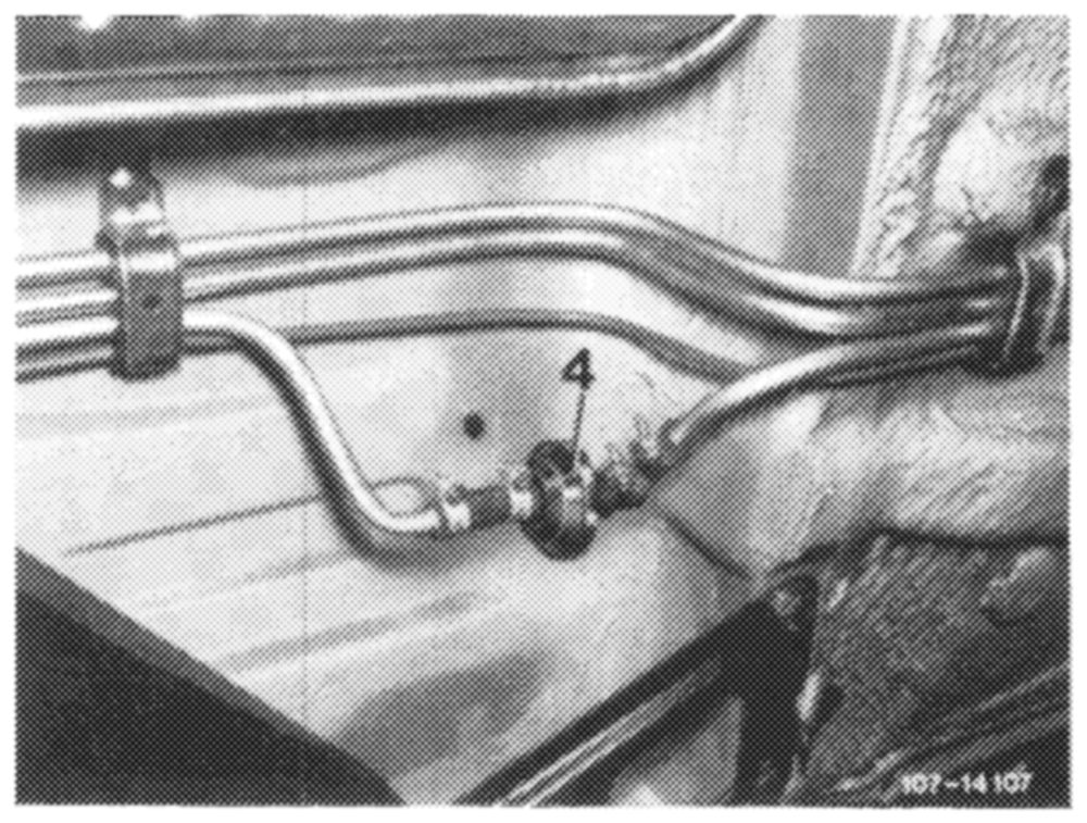
The vent valve unit is mounted underneath vehicle at level of rear legroom and takes the place of the valve system known from model year 1977.
The valve unit comprises a negative vent valve (pressure relief valve) and a positive vent valve (vacuum relief valve).
Charcoal canister
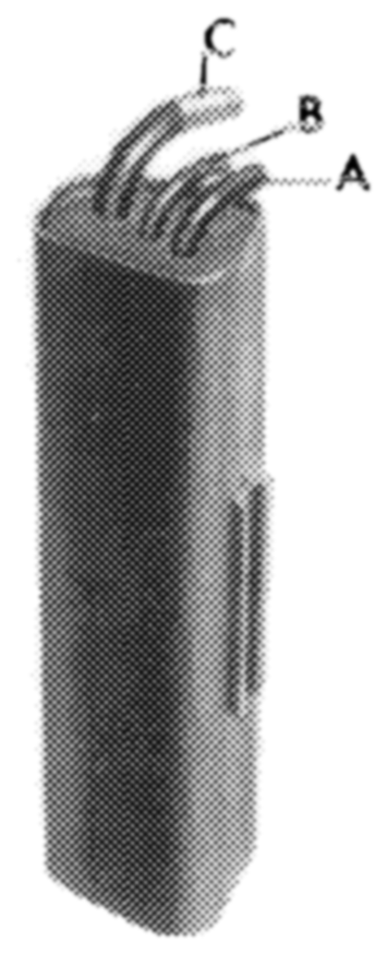
The fuel evaporation vapors from fuel tank, as well as those from float chamber, are stored in charcoal canister and are drawn off again while driving.
A Connection tank vent B_ Draw-off connection C Connection float chamber positive vent valve 107-9i31
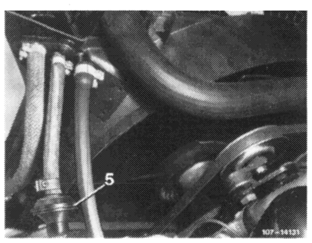
Regenerating valve
The regenerating valve (5) is located in regenerating line from charcoal canister to carburetor.
Float chamber positive vent valve
The carburetor is provided with an electromagnetic float chamber positive vent valve. The valve is actuated by switching the ignition on or off.
07.6.3—-050/18 USA 1978
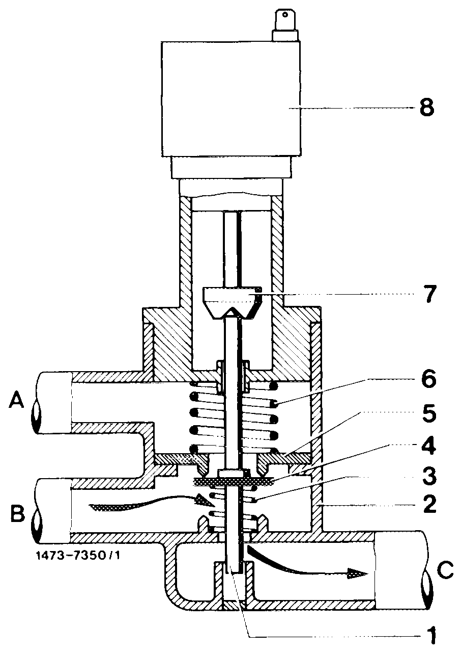
With the ignition switched off, the solenoid of the valve is de-energized. Compression spring (3) presses the valve plate (4) against upper valve seat (5). The float chamber evaporation vapors are now flowing from bore B over valve seat through connection C to charcoal canister (external venting).
With the ignition switched on, the valve is energized. The solenoid (7) moves down and pushes the valve rod (1) in downward direction. Valve plate (4) closes connection C. The carburetor is switched to internal venting. The float chamber is now vented through bore A via valve through bore B.
Draw-off connection on carburetor
To draw fuel evaporation vapors from charcoal canister the carburetor is provided with a draw-off connection (118), which is provided with a vacuum in dependence of the throttle valve position.
07.6.3-050/19 USA 1978
Fuel tank cap
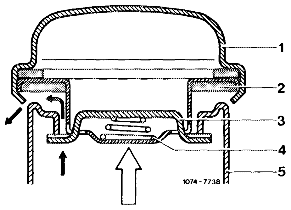
To avoid increased overpressure in fuel tank, the fuel tank cap has been modified.
Evaporation system
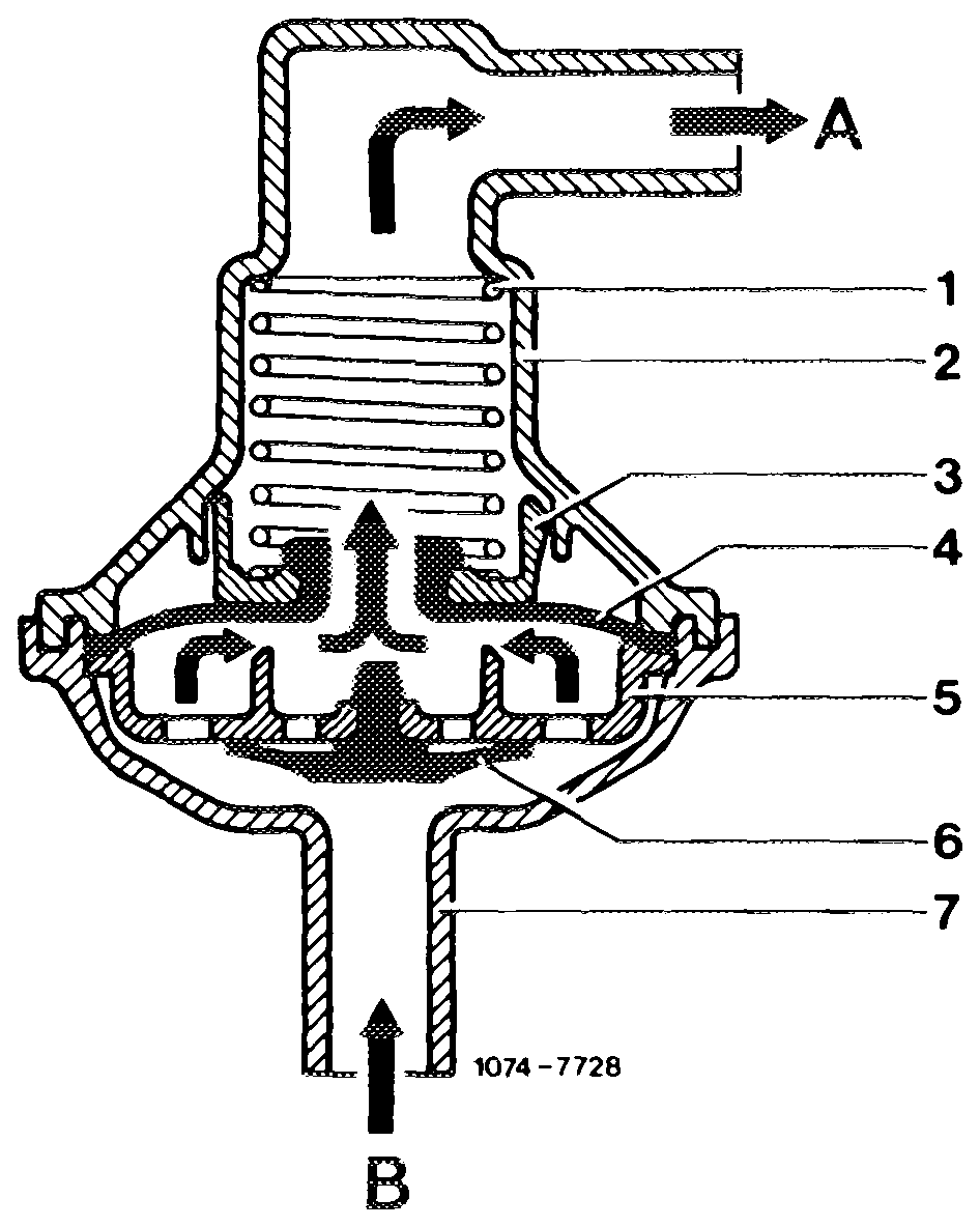
The vent valve unit (4) increases the pressure in fuel tank to 30–50 mbar. As a result, fewer fuel evaporation vapors will be able to escape from fuel tank.
When the pressure in fuel tank is at 30–50 mbar, the vent valve unit (4) opens and permits the fuel evaporation vapors to flow to charcoal canister, where they are stored when the engine is stopped.
Vent valve unit open to charcoal canister 1 Compression spring 6 Positive vent valve 2 Valve housing 7 Connection 3 Spring retainer A_ Connection charcoal 4 Negative vent valve canister 5 Valve plate B Connection fuel tank
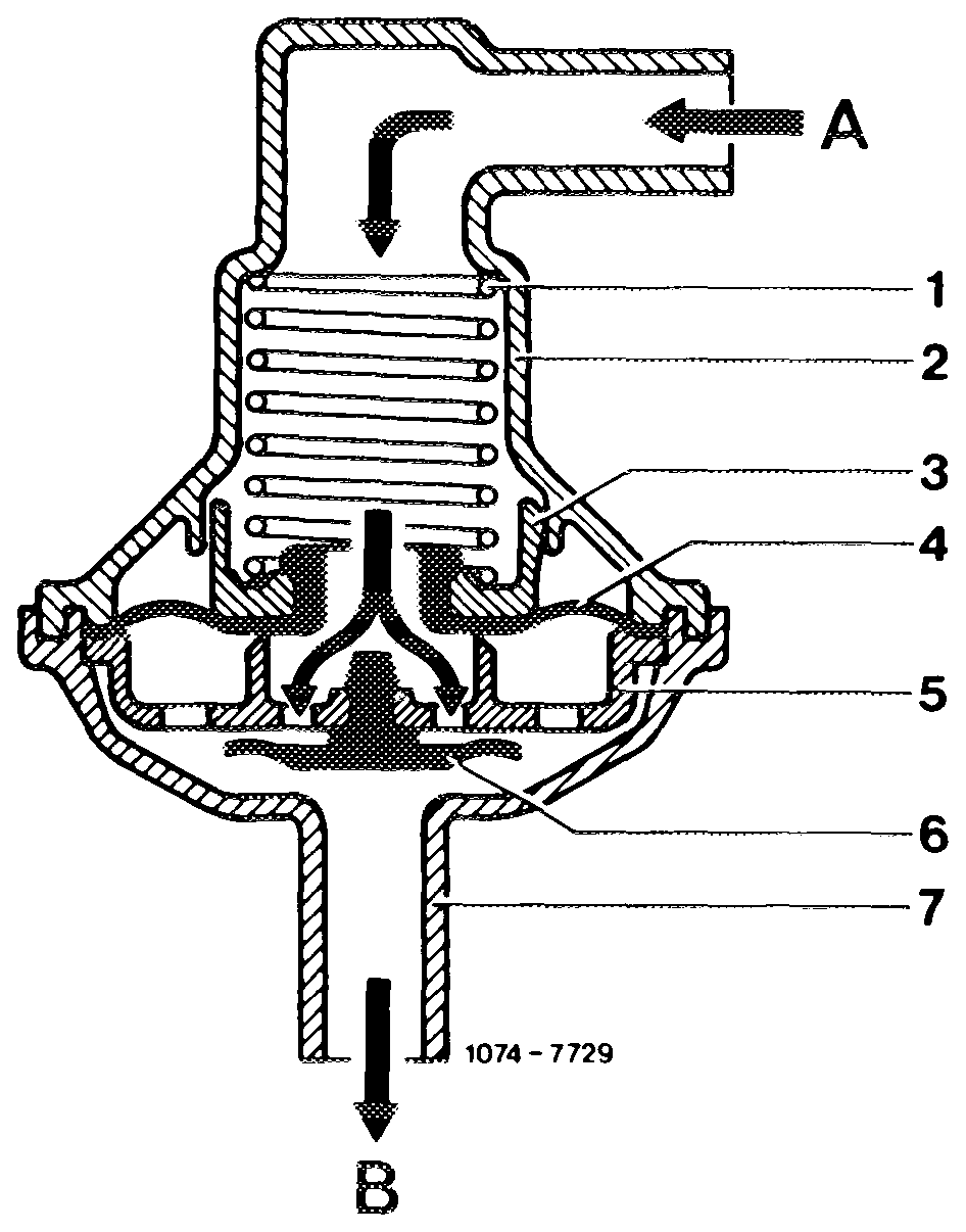
When the fuel cools down, the intake of air or fuel evaporation vapors from charcoal canister via positive vent valve (6) will compensate a vacuum of 1–16 mbar. If the vacuum in fue! tank drops below 1 mbar, the Positive vent valve (6) will close.
If the pressure in the fuel tank increases above 0.1–0.3 bar due to a malfunction in the fuel evaporation system, the fuel vapors escape via the fuel tank cap.
Vent valve unit open to fuel tank
07.6.3-050/20 USA 1978
The fuel evaporation vapors from float chamber are routed to and stored in charcoal canister with the engine stopped and the ignition switched off via float chamber positive vent valve.
Regenerating system
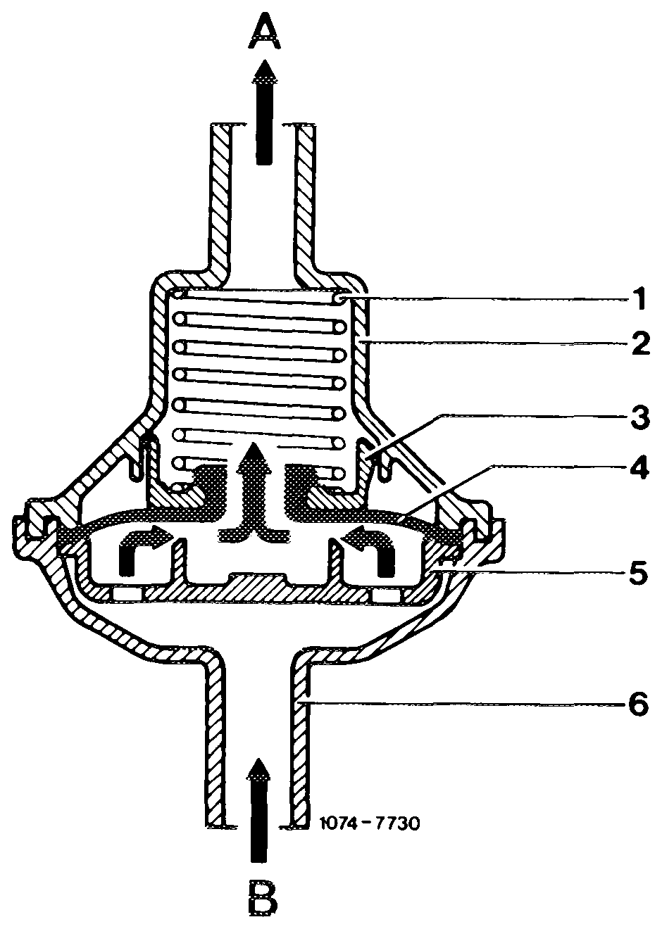
The charcoal canister is connected to the carburetor by means of a line in which the regenerating valve (5) is enclosed.
When the engine is running and the vacuum in the regenerating line exceeds 30–50 mbar, the regenerating valve opens. The fuel vapors stored in charcoal canister can be drawn off depending on throttle valve position of carburetor.
Regenerating valve (open)
1 Compression spring 5 Valve plate
2 Valve housing 6 Connection
3 Spring seat A Connection throttle valve housing 4 Negative vent valve B Connection charcoal canister
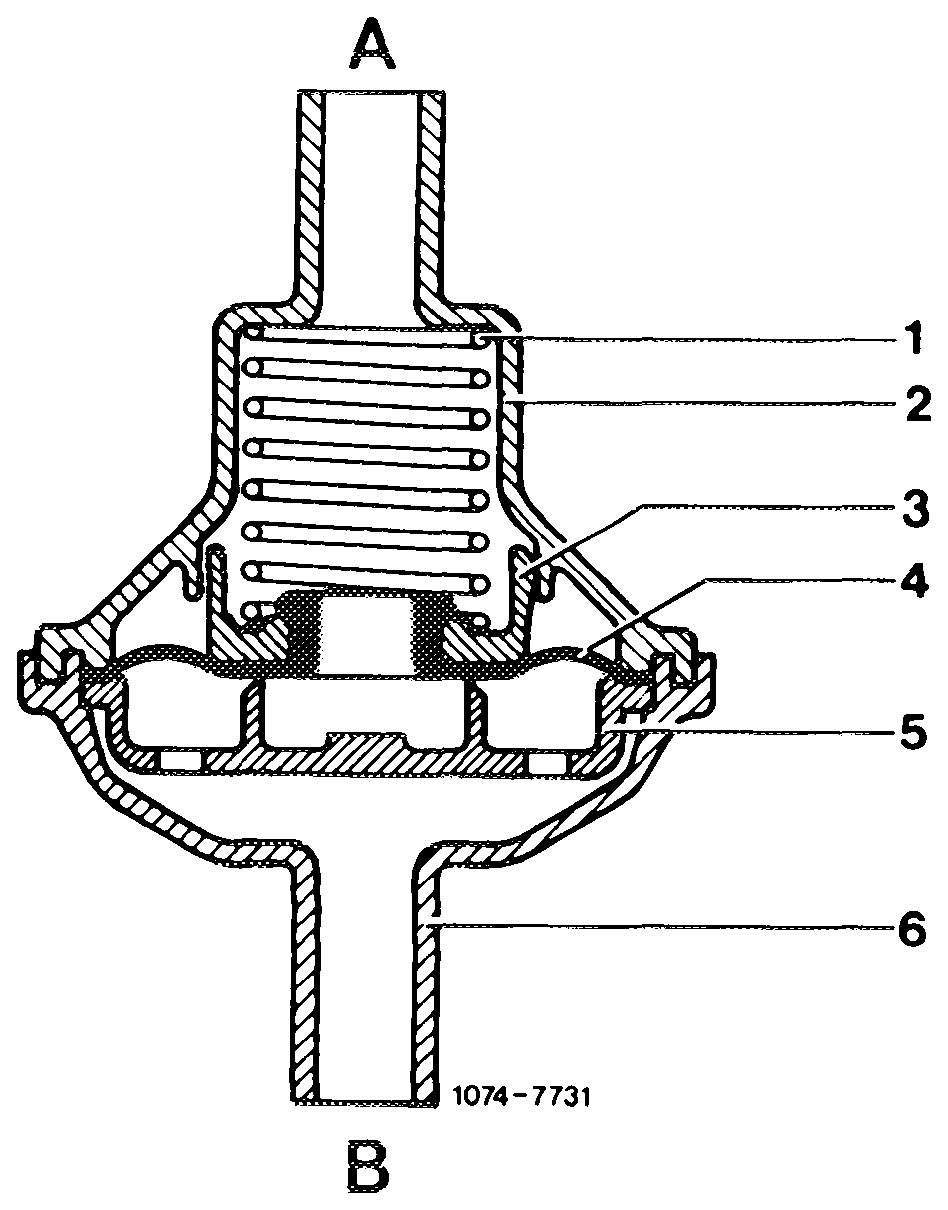
When the throttle valve opens, the two regenerating bores in carburetor, which are entering a common duct, are both passed over one after the other. As a result, regeneration in lower partial load range begins in dosages which are not influencing the driving characteristics.
At idle and during deceleration (throttle valve closed) the two regenerating bores are at atmospheric side of throttle valve. There is no regeneration of charcoal in canister.
Regenerating valve (closed)
07.6.3–050/21 USA 1978
H. Vehicles for Federal version high altitudes model year 1977
Vehicles for Federal version high altitudes are identical with Federal version. But for extended driving in high altitudes the altitude correction requires adjustment and the idle speed emission value in the higher altitude must be checked or readjusted, if required.
Altitude correction
The carburetor is set to sea level and for this reason supplies too rich a fuel-air mixture at higher altitudes, a consequence of low air pressure.
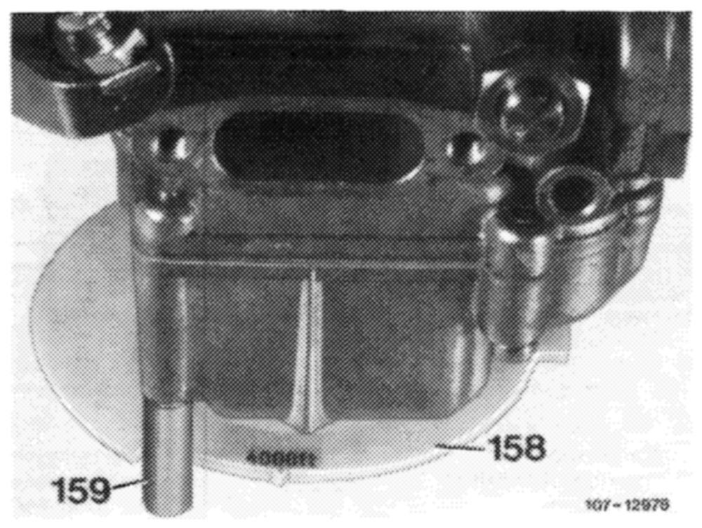
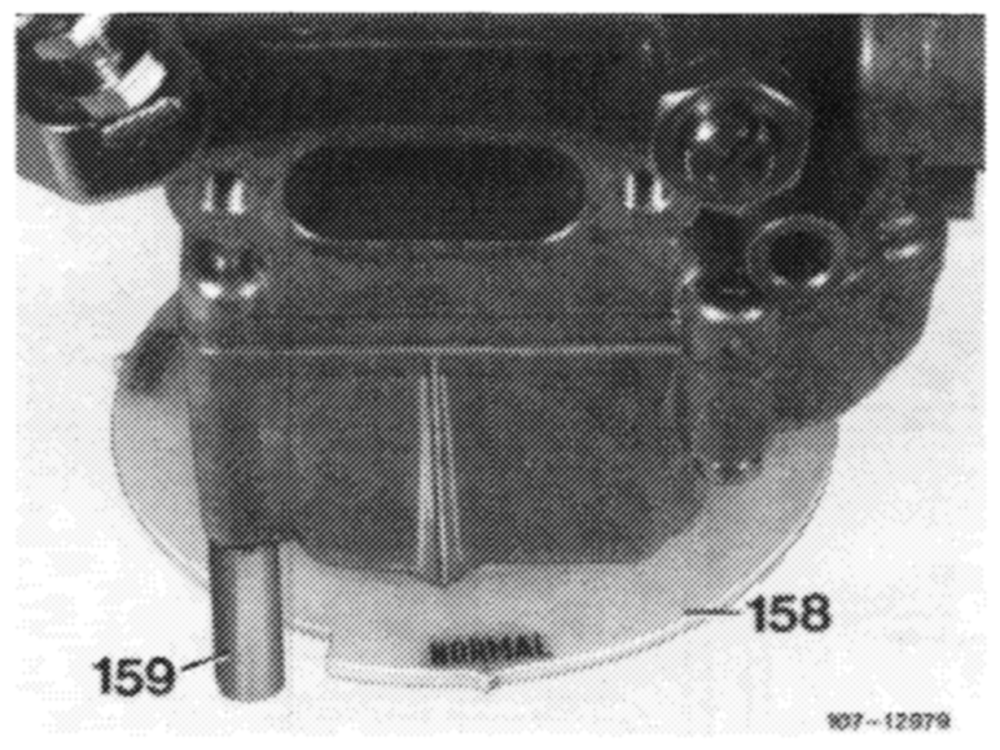
158 Hand wheel 159 Stop
By turning hand wheel (158) clockwise the fuel nozzle is displaced in upward direction. As a result, the fuelair mixture will become leaner throughout entire speed or load range.
The circumference of the hand wheel (158) shows two altitude marks with stops.
NORMAL = up to approx. 1,200 m (4,000 ft)
4,000 ft above approx. 1,200 m (4,000 ft)
Up to an altitude of approx. 1,200 m (4,000 ft) the hand wheel should be set to the normal mark.
During predominant or constant operation at altitudes above approx. 1,200 m (4,000 ft) turn hand wheel clockwise to 4,000 ft mark.
Then check idle speed emission value and idle speed in respective altitude and adjust, if required.
If the vehicles are again operated for extended periods in low altitude or at sea level, turn hand wheel back to normal!, also check idle speed and idle speed emission value and readjust, if required.
07.6.3—-050/22 USA 1977