_—_— Engine breather — functional description
WIS 01-040
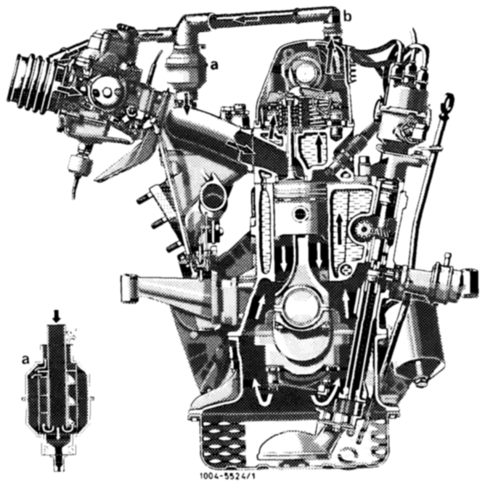
This engine has a closed, service-free crankcase breathing system.
The engine blowby gases and cylinder crankcase vapors flow through connection (b) in cylinder head cover to water separator (a) on intake pipe or in air filter.
The gases will condensate in water separator and settle on walls of separator.
Engines 115.932/926/951
a Water separator b Connection
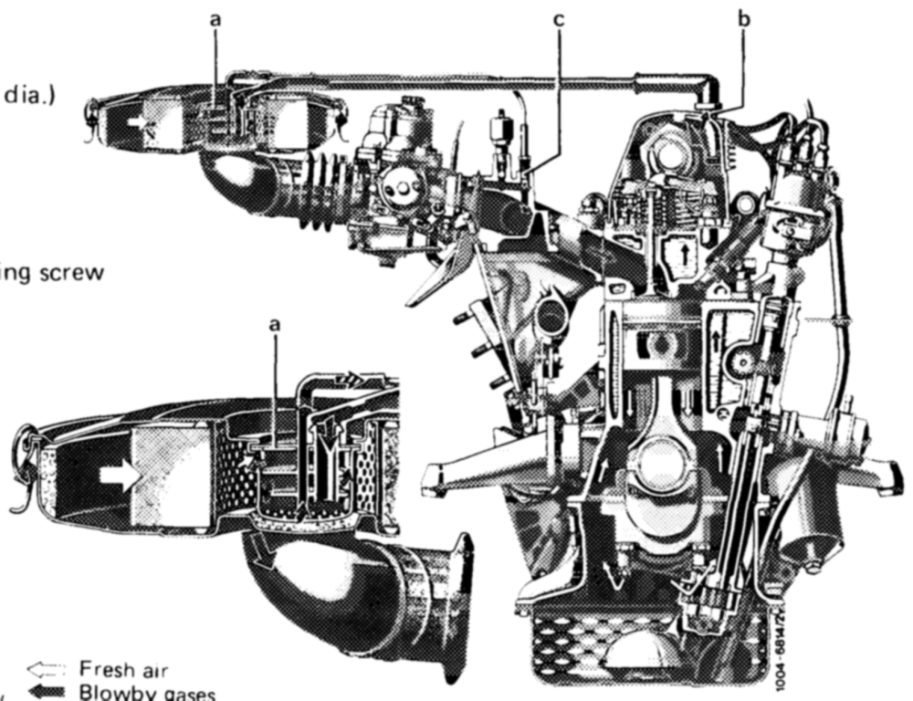
From here, the condensate and the blowby gases are drawn via the by-pass bore directly into intake pipe and will flow with the intake air into the combustion chambers.
Engines 115.923/926/951
By-pass bore in water separator (2 mm
Engines 115.938/939/954
By-pass bore in by-pass mixture adjusting (1,5 mm dia.)
Engines 115.938/939/954
a Water separator b Connection c By-pass mixture adjusting screw gases
In lower and medium performance range clean air will be additionally drawn in by the air filter and the intake pipe vacuum, in dependence of the prevailing condensate and blowby gases.
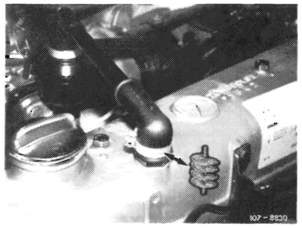
In upper performance range, blowby gases and crankcase vapors will also flow to rubber sleeve in front of carburetor or to clean air end of air filter. They will flow with the intake air via the carburetor into the combustion chambers.
During the periods shown in the following table, given national versions were provided with a flame arrester filament in connecting point on cylinder head cover.
Starting October 1974 up to start of model year 1977 G@ Starting January 1973 up to start of model year 1976
The flame arrester filament must be cleaned with benzine and a blast of air during each service.