General description of breakerless transistorized coil ignition system TSZ 4
WIS 15-530
Note
Starting model year Cs) 1978 the engine is provided with a breakerless transistorized coil ignition system TSZ 4.
This ignition system is widely free of maintenance a requirements and guarantees adequate ignition voltage Gefahrliche Hochspannung! also at max. speeds, and a more accurate adherence Vorsicht bei Arbeiten an der to firing point. Zundanlage
Danger! High voltage Ignition coil and pre-resistances are similar to those Observe caution when working of contact-controlled transistorized ignition. However, on the ignition system the switching unit has been changed with regard to its electrical layout. Danger! Haute tension Attention lors de travaux au Identification: yellow paint dot on housing top and systeme d’allumage d different Bosch number. “1184-9352
Components of ignition system
Ignition coil
Design and external dimensions of the ignition coil are similar to those of a normal high-performance ignition coil. However, the coil layout is different. The transformation ratio amounts to approx. 1 : 185, as compared with 1 : 100 for conventional ignition coils.
External identification: blue paintwork.
Pre-resistances
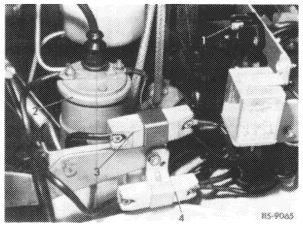
Resistances 0.4 22 and 0.6 {2 are similar to those of former ignition coil pre-resistances: The resistance coil is surrounded by a ceramic body, with projecting connections.
A sheet metal clamp is placed around ceramic body for attachment. The color of this clamp provides information with regard to resistance value, which is also punched in as a number.
1 Cable shoe for test connection 3 Resistance 0.4 4 Resistance 0.6 Q
15,.3-530/1 F2
Color Code number Resistance
| anodized, blue | 0.4 | 0.42 |
| anodized, metallic | 0.6 | 0.6 Q |
Switching unit
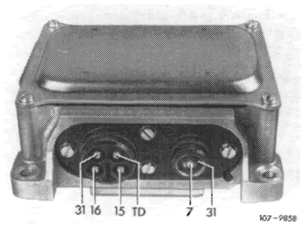
The housing of the switching unit has been newly designed.
The switching unit contains several transistors, resistances and other electronic components in a metal housing. This metal housing protects the components against mechanical damage and splash water and serves also for dissipating the electric heat. Contacting on switching unit is effected by a 4-point round plug connection with separate coaxial connection for activation.
In the event of repairs, only the complete switching unit can be replaced.
Ignition cable
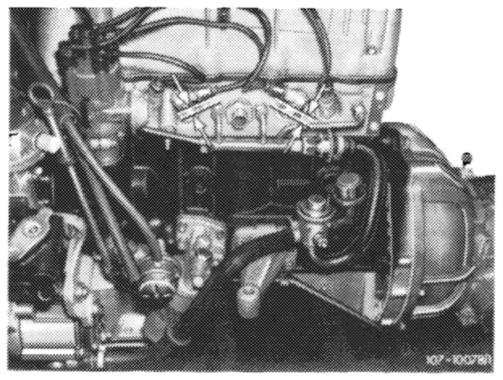
Owing to closeness of air injection line, pay attention to location of ignition cables of cylinders 2 and 3 (arrow).
Arrange ignition cables or spark plug connections according to illustration.
Layout of ignition cables
Ignition distributor
Instead of a set of contacts, the ignition distributor is provided with a transmitter section which operates according to the induction principle. Adjustment in relation to engine depending on rpm and vacuum, is made as known by means of centrifugal force and vacuum adjuster in ignition distributor.
1§.3-630/2 F2
Operation of transmitter section
A rotor made of magnetically soft steel, with its number of teeth corresponding to number of cylinders of engine, produces during its rotation per tooth a change of magnetic flux in a magnetic field established by a permanent magnet. As a result, an induction coil located in magnetic field establishes a control voltage (0.3 V—100 V) which depends in its size on engine speed, with a steep change from positive to negative half wave. This steep change of polarity of control voltage is used in switching unit following zero passage for impulse shaping, impulse amplification and interruption of primary current.
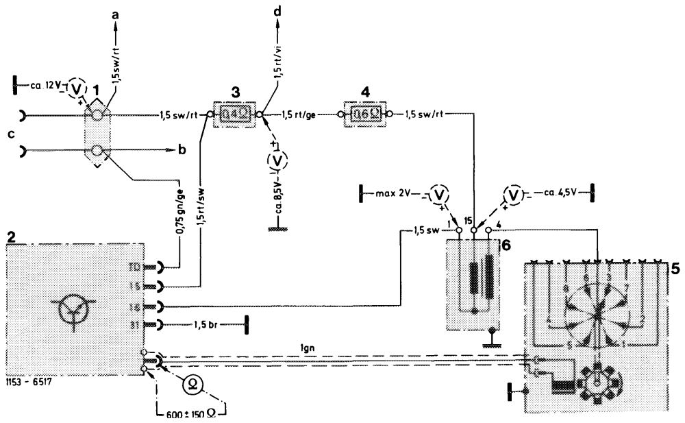
If the primary current is interrupted, the ignition voltage is induced in secondary winding of ignition coil. The dwell angle control in switching unit adapts the current flow time of primary current to the engine speed, that is, the dwell angle will also become larger with increasing speed, so that adequate ignition voltage is assured also in upper speed range.
Wiring diagram breakerless transistorized coil ignition with measuring points for voltage test 1 2-point cable connector a Ignition starter switch
2 Switching unit b Instrument cluster revolution counter
3 Pre-resistance 0.4 Q c Diagnosis socket
4 Pre-resistance 0.6 {2 d Terminal 16 starter Ignition distributor with transmitter section 5 Ignition coil 6