Adjusting idle speed
WIS 07.2-100
Testing and adjusting values
Idle speed 1/min Idle speed CO value %
Standard version
800-900 1.0–2.0
National version
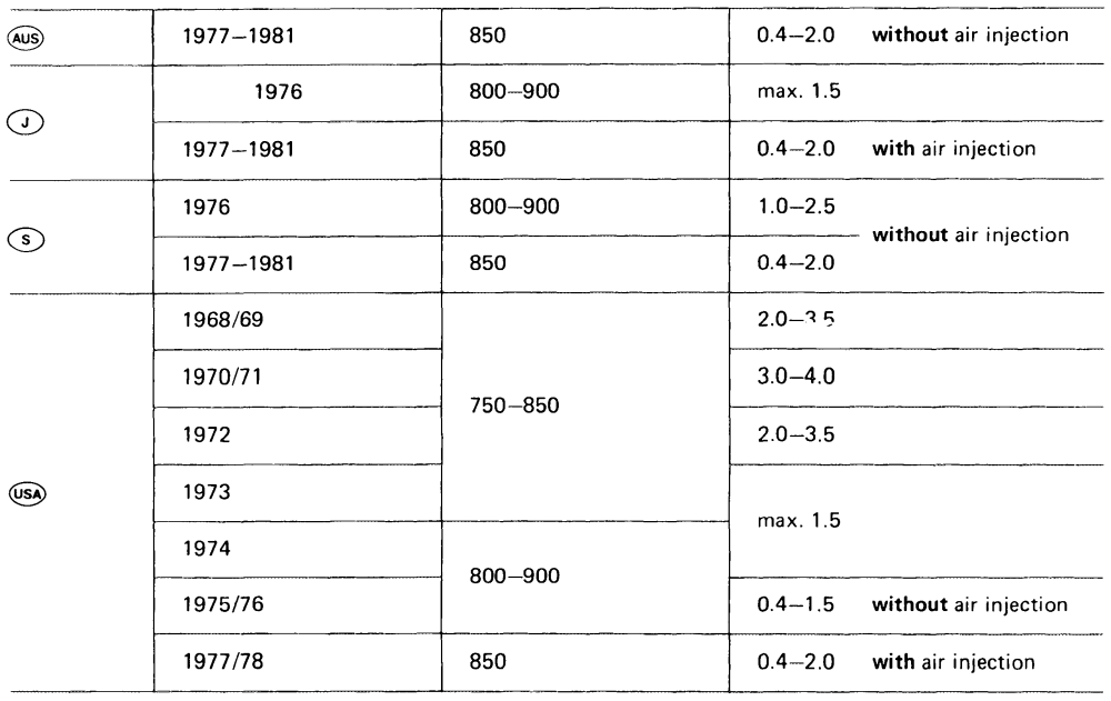
Identification: Information plate in national language on cross member in front of radiator or on cylinder head cover.
Adjust engines according to data of respective emission information plate.
Vacuum governor adjusting values!) standard and national version
Engine speed Vacuum hose pulled off 1200-1400/min
Distance between throttle valve lever and adjusting screw approx mm ae .0.5
1) When all additional units are added, the engine should still run smoothly. On vehicles with air conditioning, set to upper limit.
Special tool
Oil telethermometer – 116 589 27 21 00
008–6 212
Conventional tools
Revolution counter, CO measuring instrument
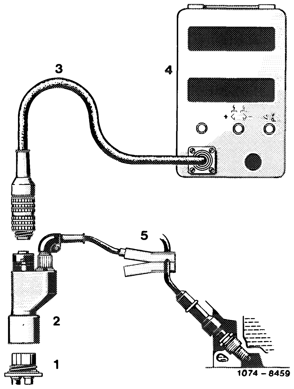
Digital tester e.g. made by Bosch, MOT 001.03
Note
Do not adjust idle speed when engine is too hot, e.g. directly following a fast drive or after performance measurements on dynamometer.
Adjust idle speed CO value with air cleaner mounted, but with crankcase breather pulled off.
Adjustment
1 Connect testers:
Digital tester or revolution counter CO measuring instrument Oil telethermometer
2 Switch off air conditioning system. Move selector lever into position “P’’, shut off righthand side of vehicle heater.
3 Run engine oil temperature to 75—85 °C.
4 Check intake system for leaks. For this purpose, spray all sealed areas with Iso-Oktan DIN 51 756 or benzene. A leak is indicated if engine speed or CO value are changing.
To prevent measuring errors, pull hose for preheating intake air from air cleaner and close respective opening on air cleaner.
Attention! Do not use conventional fuel for spraying (unhealthy vapors!).
Pay attention to inflammability and do not spray on red-hot parts or parts of ignition system.
5 With engine running, check whether throttle valve shaft operates easily and whether throttle valve lever rests against idle speed stop.
By lifting throttle valve lever, increase speed to approx. 2000–2500/min. Then release throttle valve lever. Lever should return automatically to idle speed stop and stay there securely.
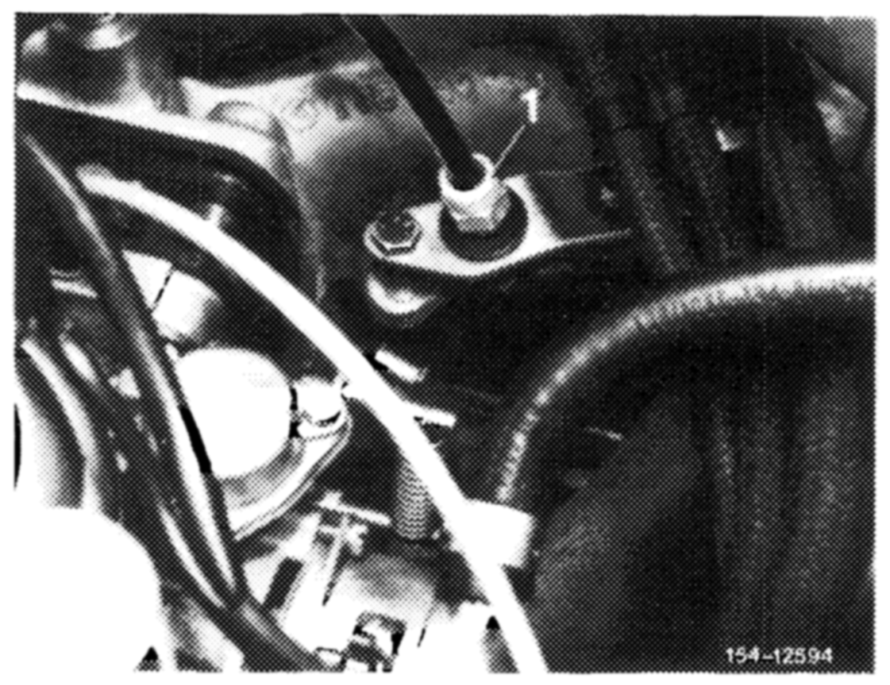
On vehicles with cruise control/Tempomat, check whether Bowden wire rests free of tension against regulating lever. Adjust with adjusting nut (1), if required. Run engine for this purpose.
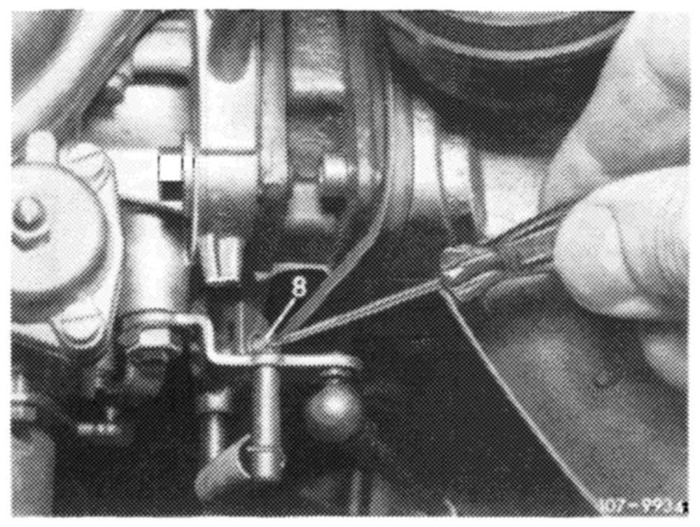
6 Adjust idle speed.
a) Model 115
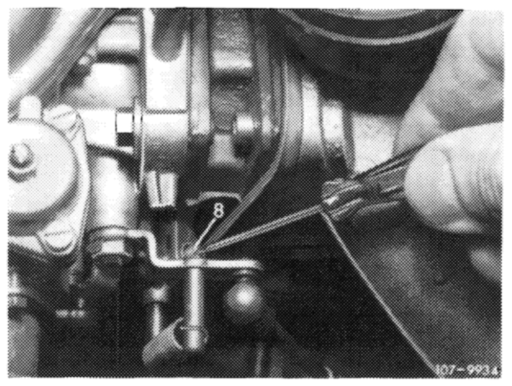
Adjust idle speed with adjusting screw (8).
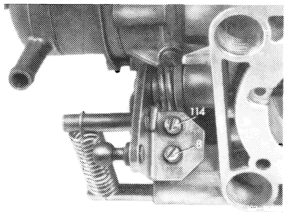
Model 115 Carburetor version 1
Model 115 Carburetor version 2 (national version only)
b) Model 123
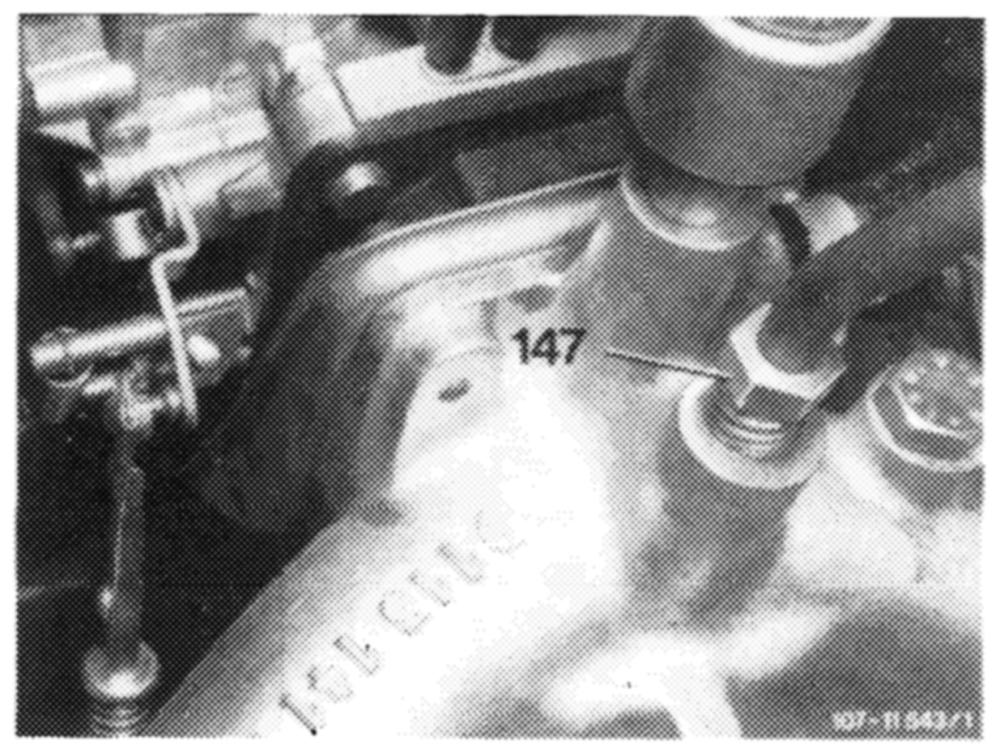
Adjust idle speed with adjusting screw (147).
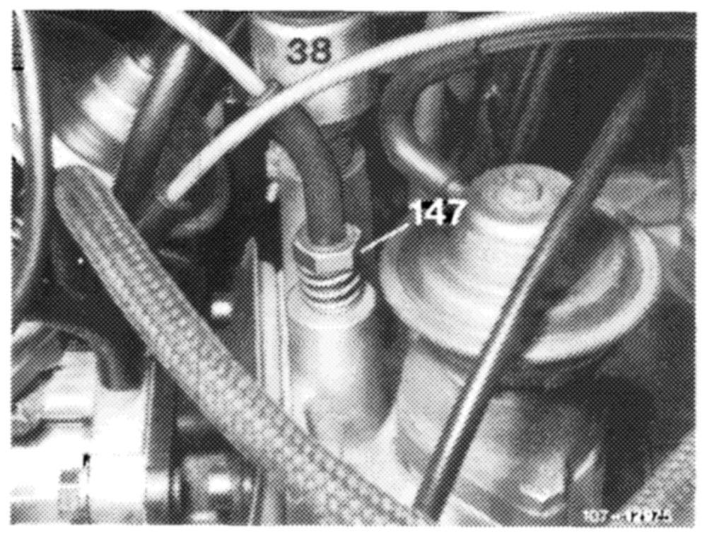
Standard version
National version
7 Check idle speed CO value and adjust, if required.
On national versions G) GS GS make sure of the following prerequisites prior to checking or adjusting idle speed CO value depending on version of emission control system and model year:
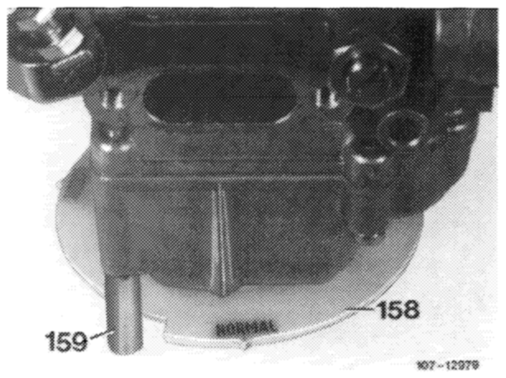
On carburetors with altitude adjustment, check whether hand wheel (158) is set on correct mark and adjust, if required.
4000 ft and below
Normal
above 4000 ft (high altitude)
4000 ft
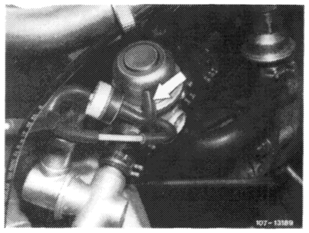
@us) 1977–1980
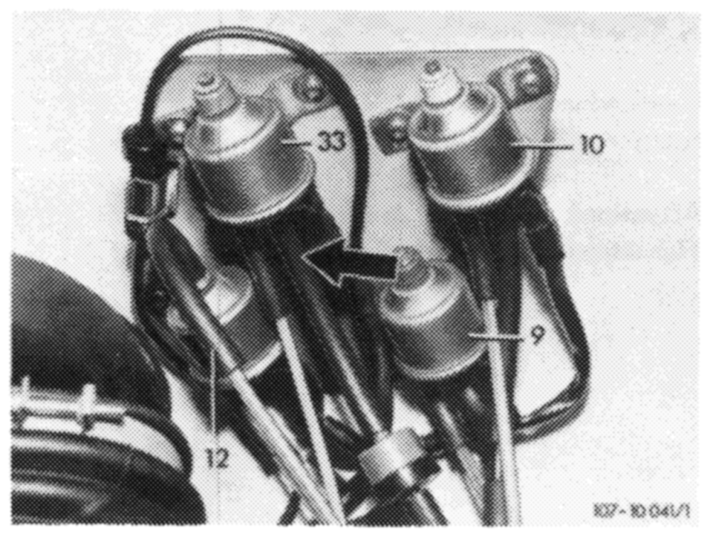
Pull off vacuum hose (arrow) (air injection not operating).
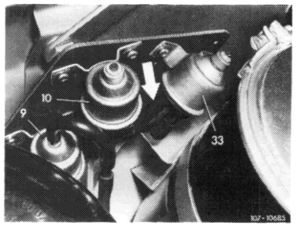
Cs) 1976
Pull off vacuum hose (arrow) (air injection not operating).
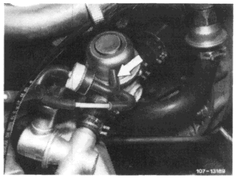
CS) 1977-1980
Pull off vacuum hose (arrow) (air injection not operating).
Gs) 1975/76
Pull off vacuum hose (arrow) (air injection not operating).
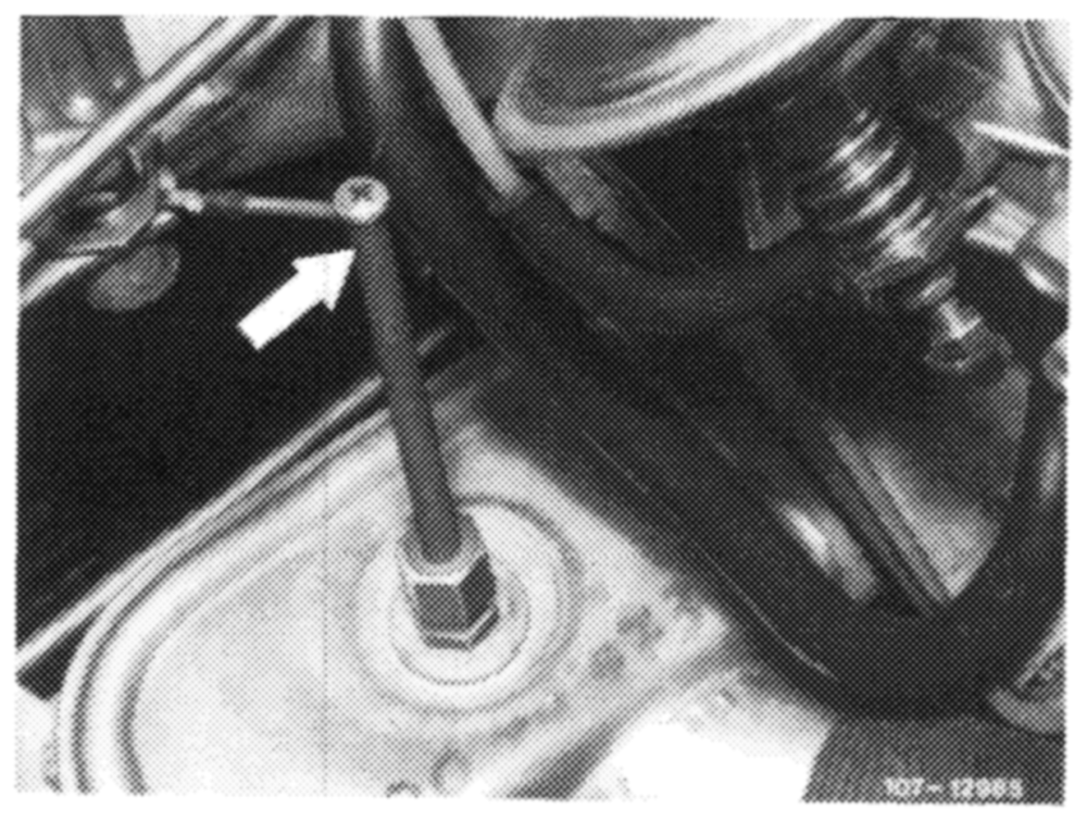
Starting model year 1977 C2) and @sa) the air injection need no longer be made inoperative for idle speed CO test or adjustment, since the exhaust gas is taken from tapping pipe (arrow).
Arrow = exhaust gas tapping pipe
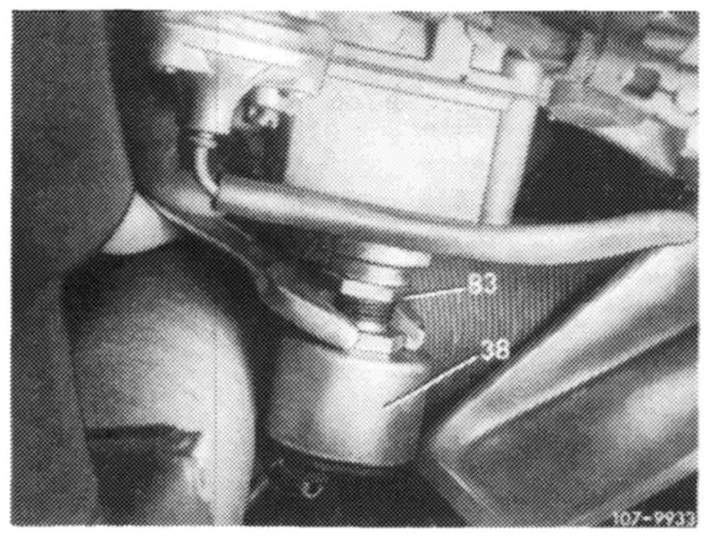
Adjust idle speed CO value:
a) Model 115 standard and national version
Adjust idle speed CO value by means of idle speed shutoff valve (38).
Screwing out = richer Screwing in leaner
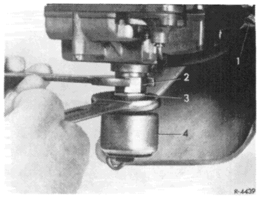
Accelerate for a short moment, check idle speed CO value once again.
On carburetors with holding screw (2) apply counterhold to holding screw when loosening hex. nut (3).
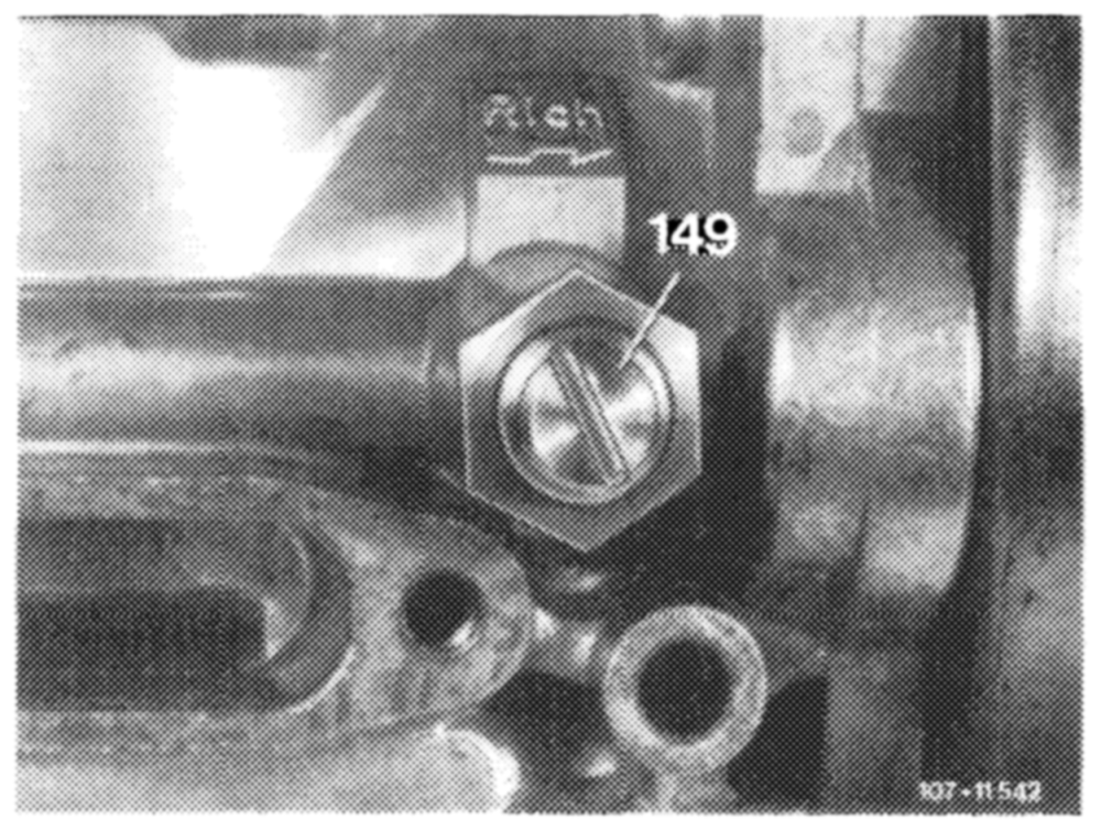
Note: On carburetors without idle speed shutoff valve, adjust idle speed CO value by means of knurled screw.
b) Model 123 standard version
Screw adjusting screw (149) completely down and counterlock with hex. nut.
Attention! This adjusting screw must remain closed.
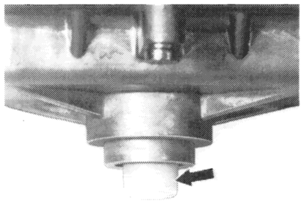
If the idle speed CO value is not within limits, pull safety cap (arrow) from fuel adjusting screw.
HP FRSTS
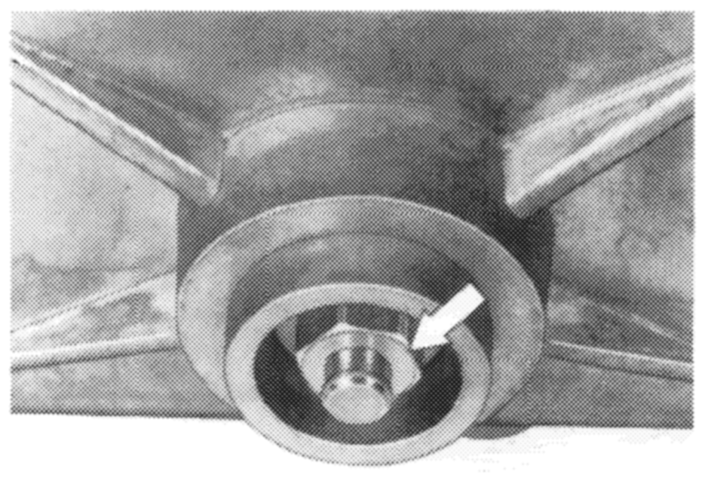
Adjust idle speed CO value by means of fuel adjusting screw (arrow).
Screwing out = richer
Screwing in leaner
Accelerate for a short moment, check idle speed CO value once again. Mount new safety cap.
WF ~19278
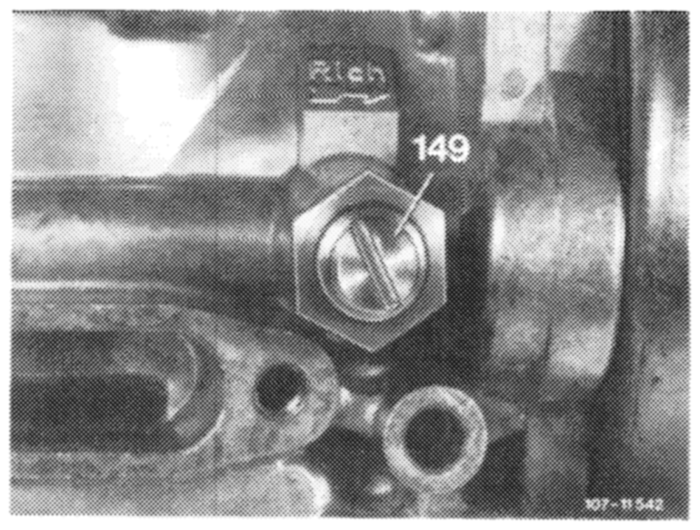
c) Model 123 O®
Adjust idle speed CO value with adjusting screw (149).
Screwing out = leaner
Screwing in richer
Accelerate for a short moment, check idle speed CO value once again.
Note: If the idle speed CO value cannot be adjusted by means of adjusting screw, check basic adjustment of fuel adjusting screw and correct, if required.
@ Plug vacuum hoses for air injection on again (air injection operating).
Check idle speed CO value again. Value should be
below value previously adjusted.
8 Adjust regulating rod:
a) Model 115 with manual! transmission
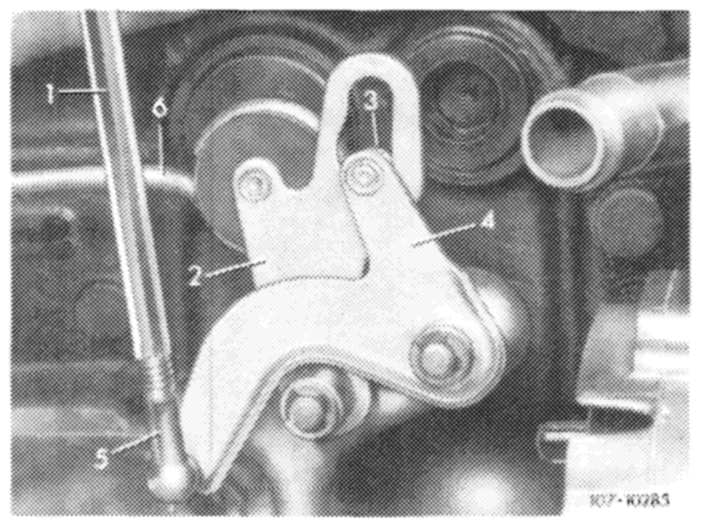
Adjust regulating rod (1) in such a manner that roller (3) rests free of tension against end stop.
b) Model 115 with automatic transmission
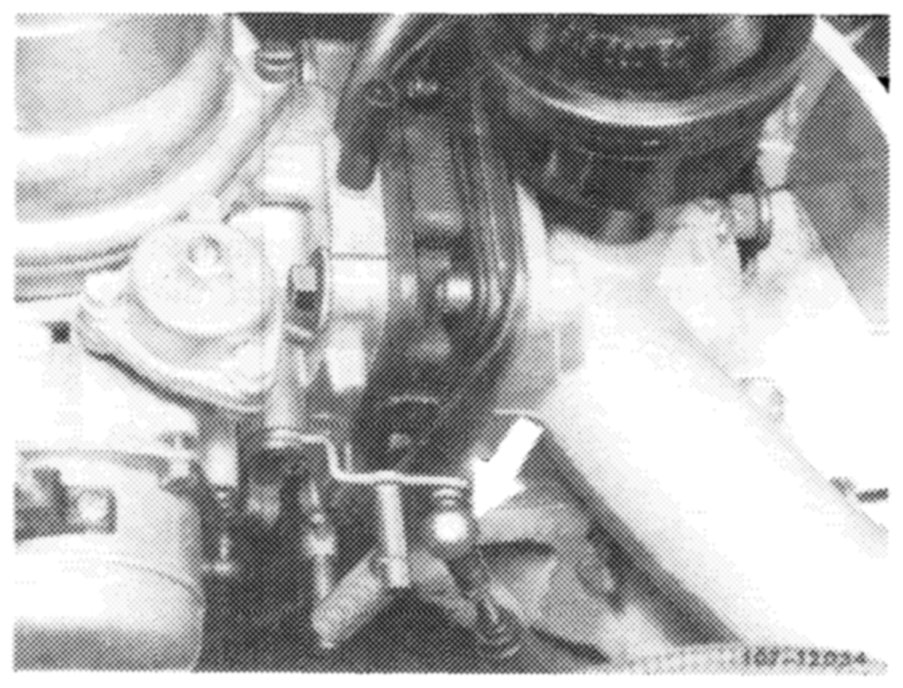
Adjust regulating rod with engine running by means of ball socket (arrow) in such a manner that rod can be attached free of tension in completely extended condition (idle path).
c) Model 115 Gs California version 1975/76
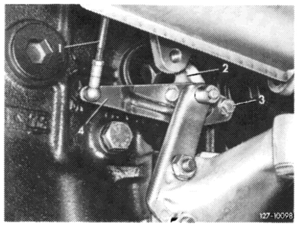
Disconnect regulating rod (1) on carburetor with engine running and push down against stop. Set ball socket in such a manner that socket can be attached free of tension to throttle valve lever.
d) Model 123 with manual transmission
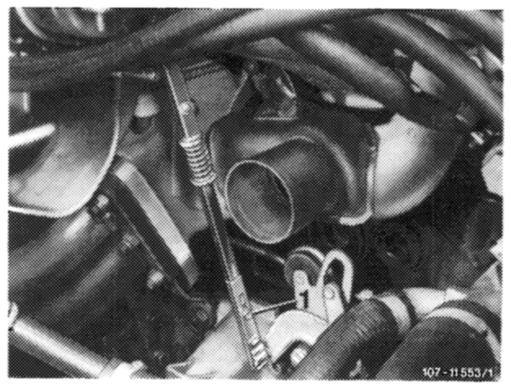
Adjust regulating rod in such a manner that the roller in guide lever rests free of tension against end stop. If required, loosen clamping screw (1) and set regulating rod accordingly.
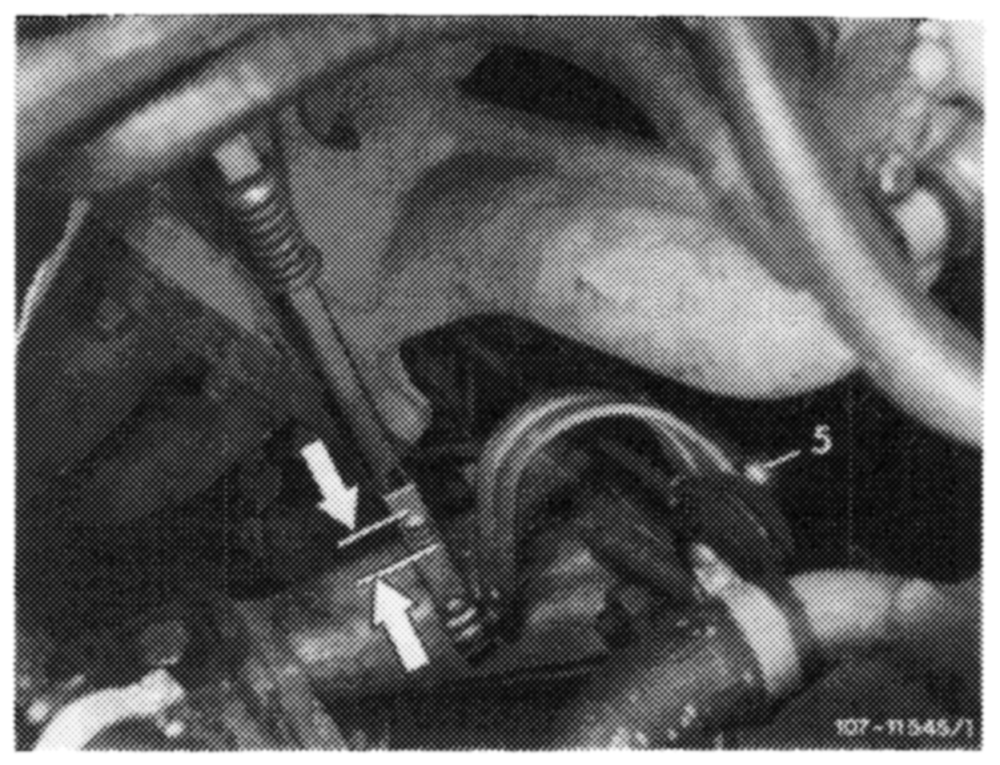
e) Model 123 with automatic transmission
Adjust regulating rod with engine running in such a manner that rod can be attached free of tension when completely extended (arrows). If required, adjust length of control pressure rod with ball socket (5) accordingly.
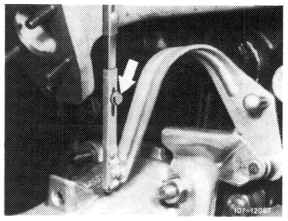
f) Model 123 with automatic transmission and air conditioning system
Adjust regulating rod with engine running in such a manner that rod can be attached free of tension when completely extended. If required, loosen clamping screw (arrow) and set regulating rod accordingly.
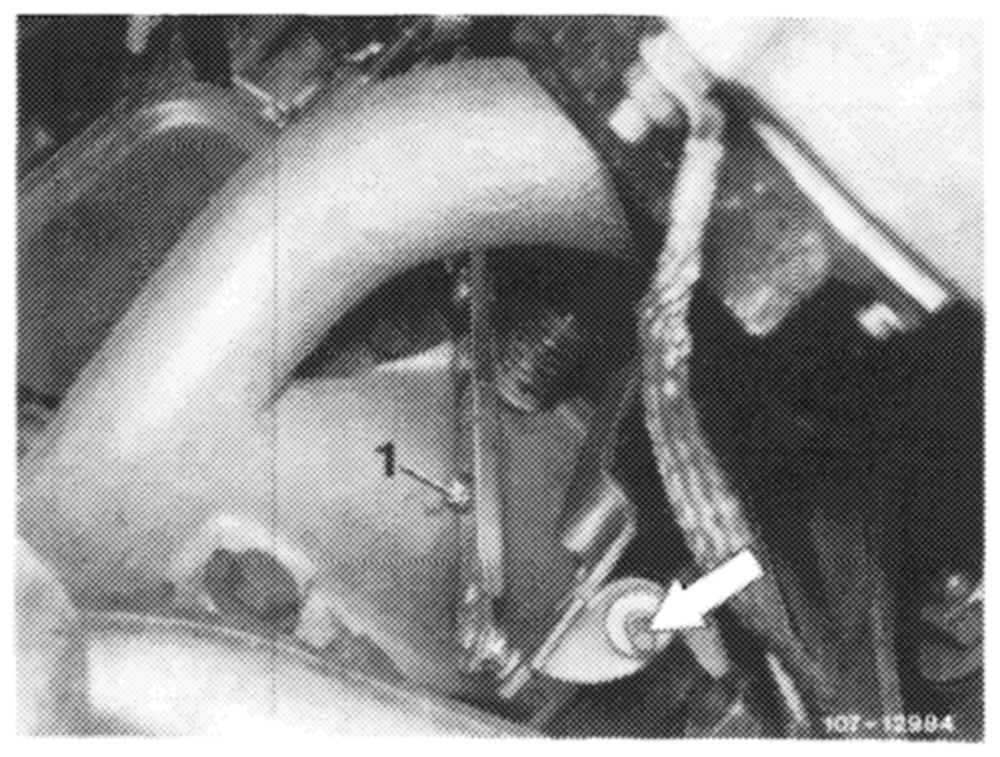
g) CD Gs starting model year 1977
Adjust regulating rod with engine running in such a manner that rod can be attached free of tension when fully extended. !f required, loosen clamping screw (1) and set regulating rod accordingly.
9 Adjust vacuum governor
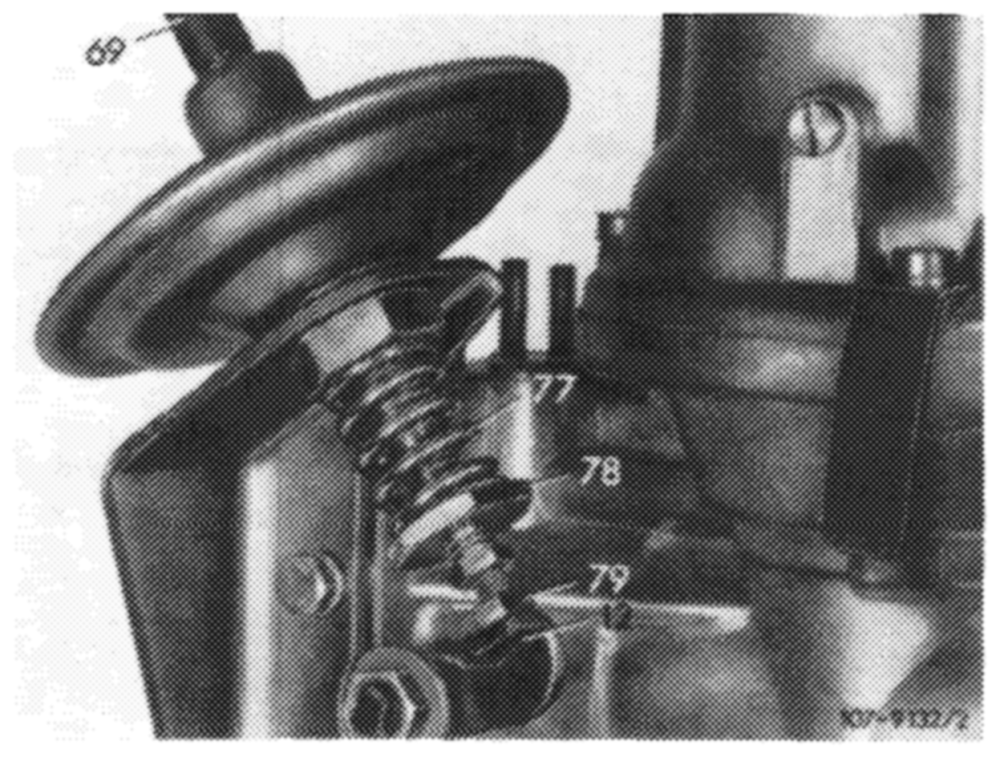
For this purpose, run engine at idle, pull off vacuum hose (69), set to specified speed by means of adjusting screw (79), plug-on vacuum hose.
Attention! When loosening counternut, apply counterhold to diaphragm rod.
Check for specified distance between adjusting screw (79) and throttle valve lever (12). If required, set with adjusting nut (78).
Move selector lever into driving position. Turn power steering to full lock and switch on air conditioning, engine should still run smoothly. If required, readjust speed by means of adjusting nut (78).