Replacing threaded bushing and valve adjusting screw
WIS 05-212
Valve clearance Cold engine (approx. 20 °C) Warm engine (60 °C + 15 °C)
| Intake | 0.10′) | 0.15′) | |
| Exhaust | 0.25 | 0.30 | |
| 1) 0.05 mm more for consistent outside temperatures below —20 °C. Tightening torques | Nm | ||
| Cylinder head cover bolts and capped nuts | 5 | ||
| Cylinder head threaded bushing | 80 | ||
| Valve adjusting screw | 20–40 | ||
Special tools
Depressor for valve spring SD – 110 589 04 61 00
a
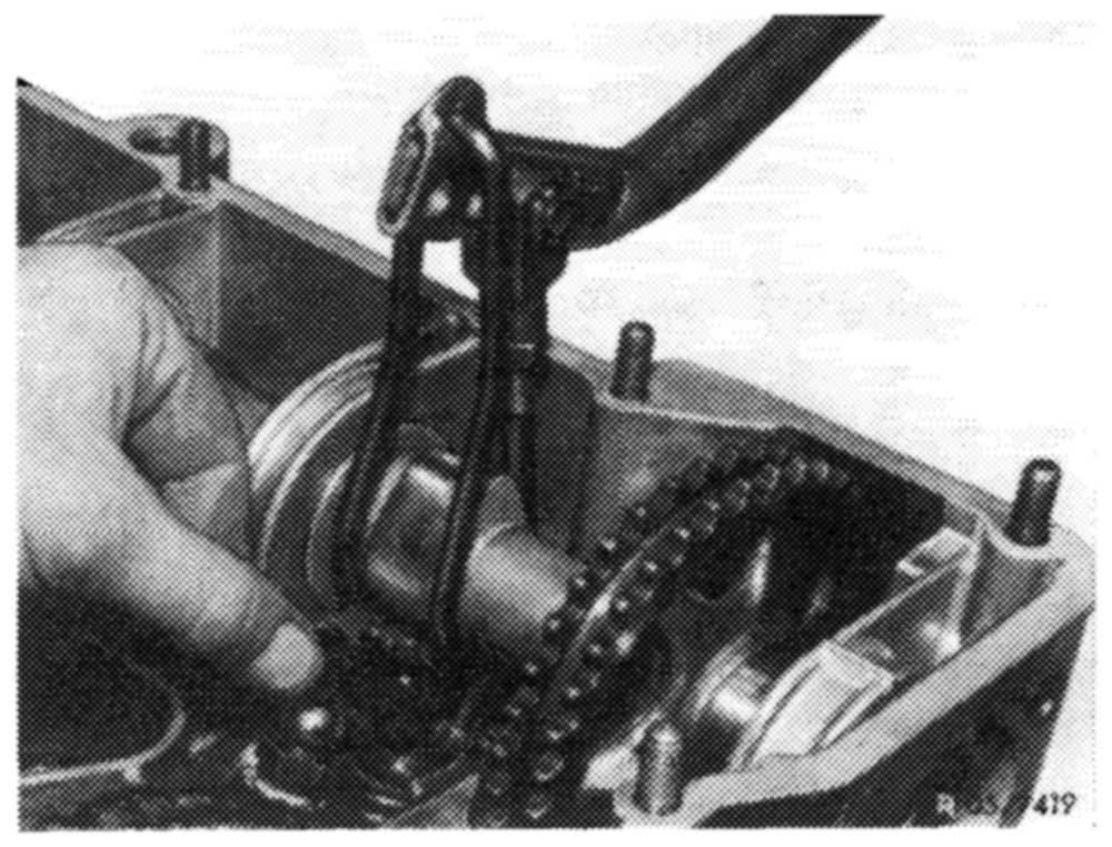
Valve adjusting wrench 7 mm, 1/2″ square, 3 for checking torque of adjusting screw 3 Valve adjusting wrench 17 mm 110 589 01 01 00 – 110 589 00 01 00
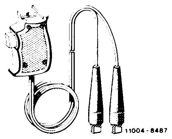
Contact grip to turn engine (part of compression recorder 001 589 46 21 00) – 001 589 46 21 08
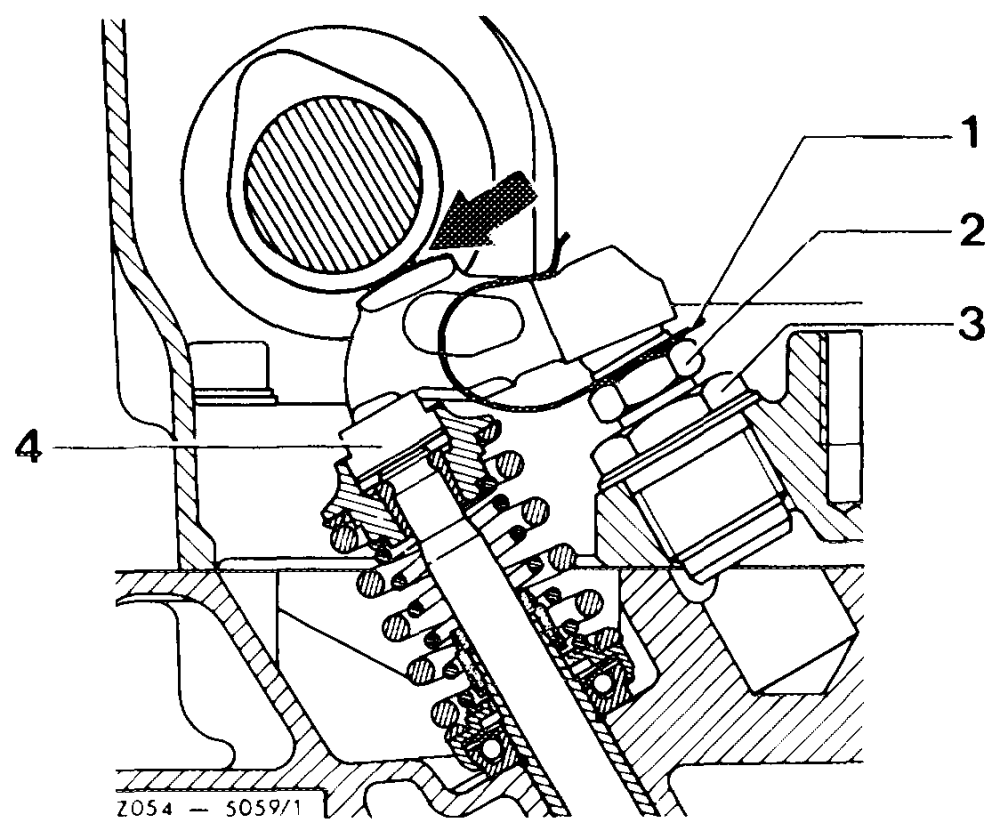
Note If torque of valve adjusting screw is less than 20 Nm (2 kpm), replace valve adjusting screw (2) or threaded bushing (3) with valve adjusting screw (2).
PWN Spring clamp Valve adjusting screw Threaded bushing Pressure pad
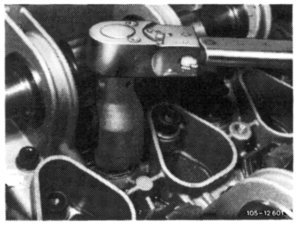
The torque can be checked with a valve adjusting wrench, part number 110 589 00 01 00 and a torque wrench (e. g. part number 000 589 27 21).
Replacing
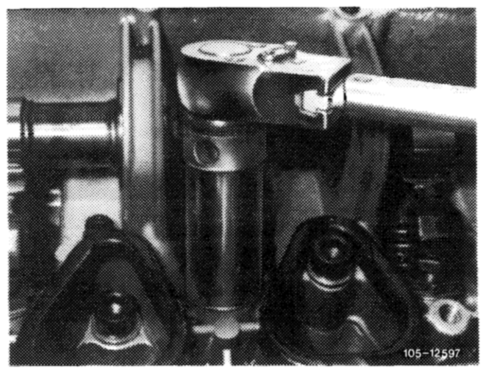
1 Remove rocker arms (05—230).
2 Unscrew threaded bushing with valve adjusting screw.
Attention!
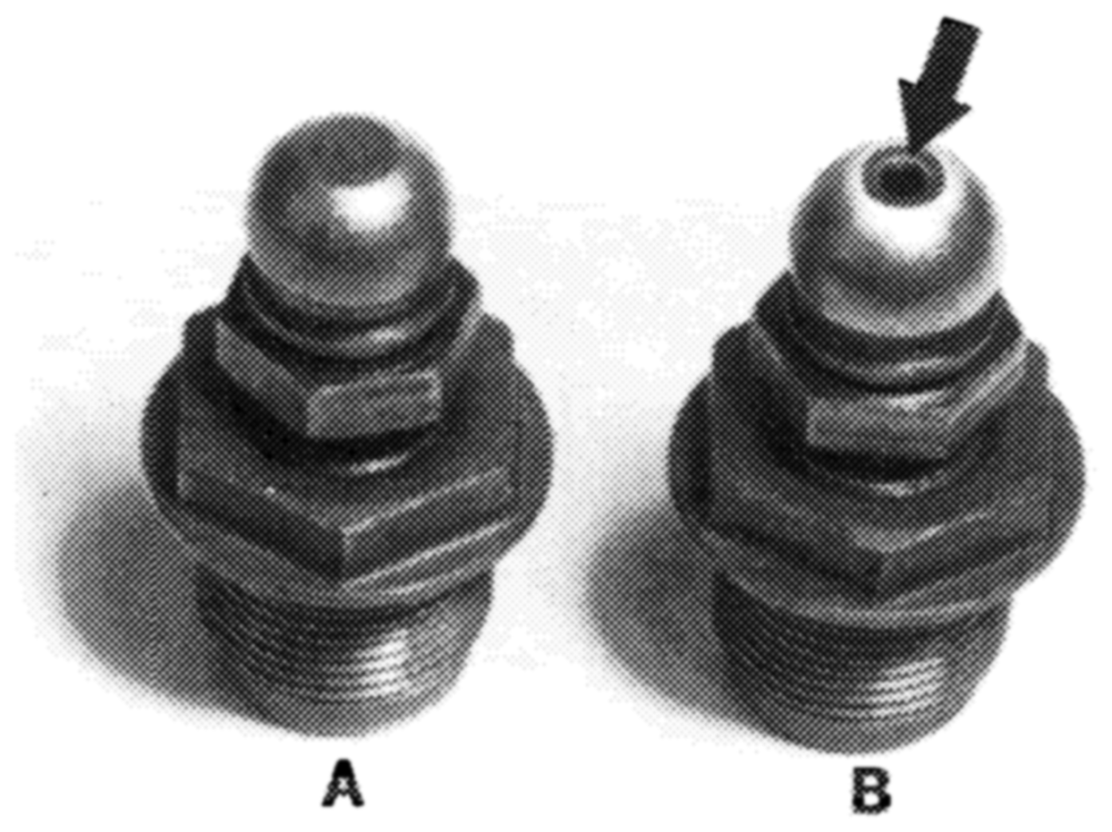
Only use valve adjusting screws with an oil bore (arrow).
3 Coat threads of threaded bushing with valve adjusting screw with tallow, install and tighten threaded bushing to a torque of 80 Nm (8 kpm).
Attention! Threaded bushing must be free of burrs when installing, since these would find their way into the oil circuit.
10512453
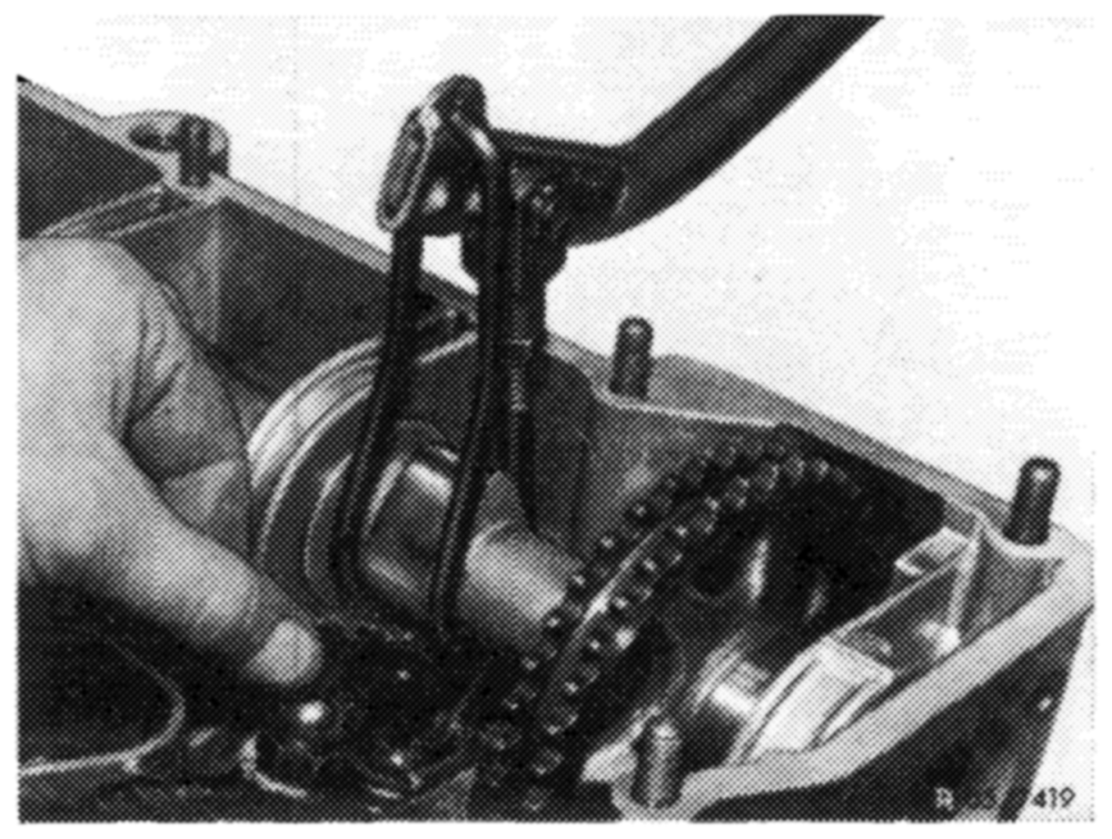
4 Install rocker arms (05—230).
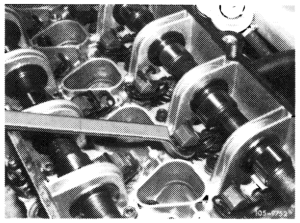
5 Adjust valve clearance (05—210).