E3 AR30.10-P-3080A Disassembling, assembling accelerator control 10.9.97
WIS 30-3080A
“z # E3 AR30.10-P-3080
ENGINE 111.946 in MODEL 170.435 ENGINE 111.921 in MODEL 202.018 /078 ENGINE 111.945 in MODEL 202.020 /080 ENGINE 111.974 in MODEL 202.023 /083 ENGINE 111.945 in MODEL 208.335 ENGINE 111.942 in MODEL 210.035 /235 ENGINE 111.970 in MODEL 210.037 /237 ENGINE 111.977 in MODEL 163.136
oe #E3 AR30.10-P-3080A 2
P30.10-0295–09
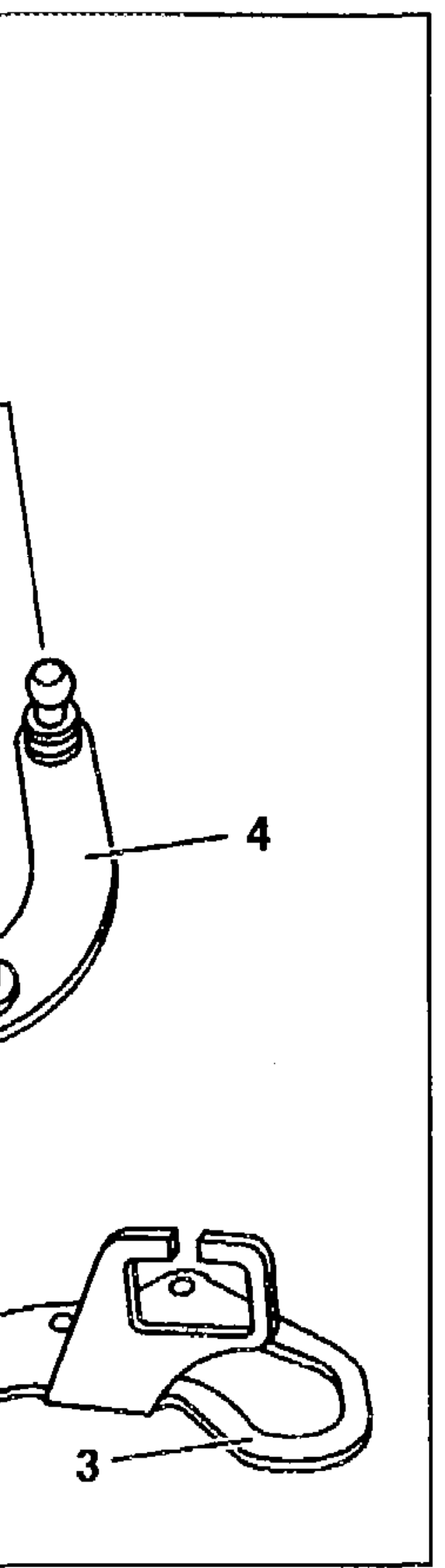
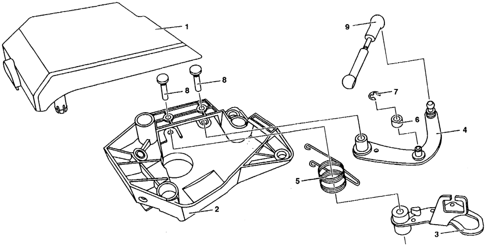
1 Cover 4 Control lever 7 Circlip
2 Bearing bracket 5‘ Torsion spring 8 Pin
3 Fulcrum lever 6 ~~ ‘Roller 9 Cannecting rod
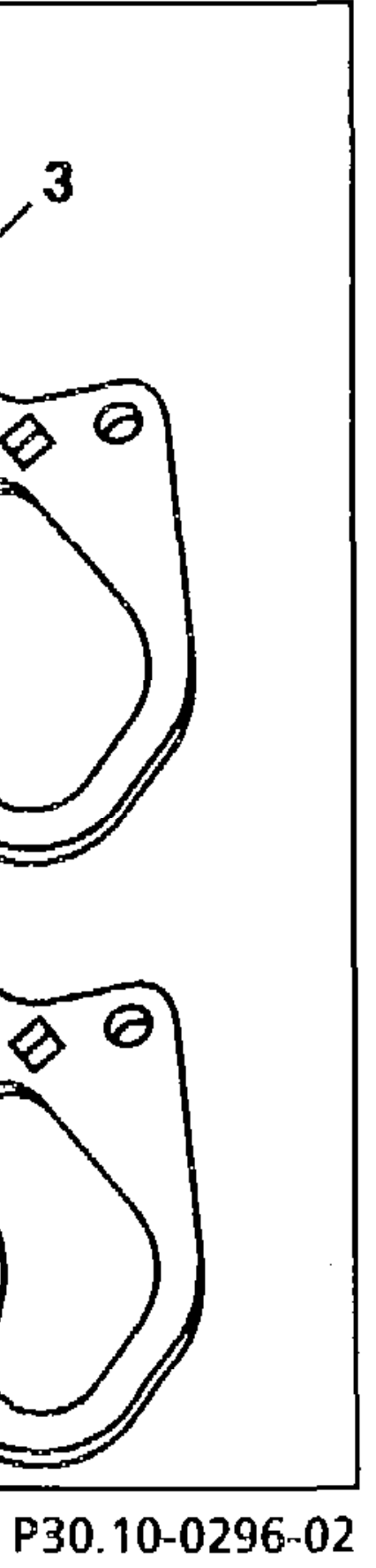
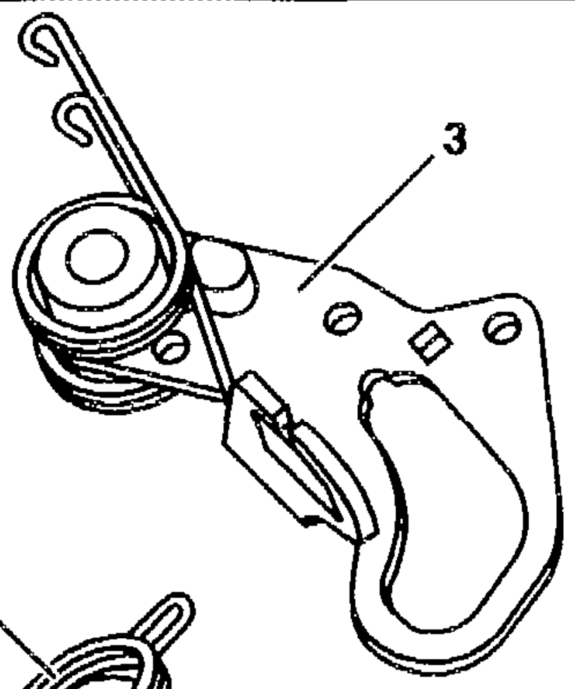
Removing/installing spring
3 Fulcrum lever
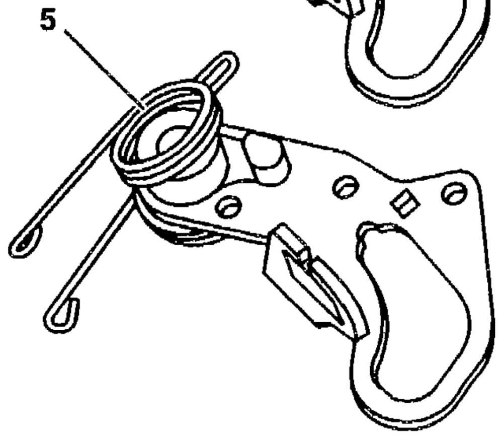
5 Torsion spring
| [7] | Disassembling | |
| 1 | Remove pin (8) from bearing bracket (2) and from the bearing hole of the fulcrum lever (3) |
2 Remove fulcrum lever (3) together with torsion spring (5)
AR30.10-P-3080A
| Detach torsion spring (5) from fulcrum lever (3) | |||
| Remove pin (8) from bearing bracket (2) and from the bearing hole of the control lever (4) | |||
| Take contro! lever (4) out of bearing bracket (2) | |||
| Remove circlip (7) from control lever (4) | circlip (7) can be necessary | ||
| Detach connecting rod (9) from control lever | |||
| Assembling | |||
| When assembling, iubricate all bearing points and joints of the accelerator contro! | grease | BRO0.45-Z-1007-06A BROO.45-Z-1011-06A | |
| Attach connecting rod (9) and roller (6) to control lever (4) | with circlip (7) | ||
| 10 | Insert control lever (4) with connecting rod (9) into bearing bracket (2) | ensure that the is located in the bearing | |
Insert pin (8) from above into bearing sufficiently far through 11 bracket (2) and into the bearing hole of the pin is touching the control lever (4) bracket
# E3 AR30,10-P-3080A
| Fit torsion spring (5) onto fulcrum lever (3) | Li] Lubricate fulcrum lever (3) at the end faces of the hub and in the bearing hole | see Fig Removing and installing spring |
| Place fulcrum lever (3) with torsion spring (5) into the bearing bracket (2) so that the roller (6) of the control lever (4) is guided by the fulcrum | ||
| Alter position of fulcrum lever (3) with torsion spring (5) so that the ends of the spring are guided through the openings of the bearing bracket (2) | ||
| Insert fulcrum lever (3) into the bearing point with the aid of the guide slots | ||
| Insert pin (8) into the bearing bracket (2) and into the bearing hole of the fulcrum lever (3) | [i] until the tip of the pin is touching the bottom of the bearing bracket | Push pin (8) sufficiently far through |
| Press both pins (8) sufficiently far into the bearing bracket (2) until there is stillagap of about 0.1 mm to 0.3 mm between the shoulder of the pin (8) and the bearing bracket (2) | [i] the axial clearance and ease of operation of fulcrum lever (3) and control lever (4) | The gap is required in order to ensure |
| Inspect ease of operation of control lever (4) and fulcrum lever (3) | Li] The levers should move by themselves from one end position to the other | |

Tension torsion spring (5) at the slots of the (® Ensure that the ends of the springs are bearing bracket (2) properly locked in place
# E3 AR30.10-P-3080A
Inspect operation of accelerator control 20
Repair products
Order number Number Designation
Anti-corrosion grease BROO.45-Z-1007-06A – 001 989 37 51 10
001 989 42 51 Anti-corrosion grease BROO.45-Z-1011-06A