Adjusting throttle control (continued)
WIS 30-1010D
AR30.10-P-1010D
51 AR30.10-P-1010D
ENGINE 104.941 /942 /943 /944 /991 /992 /994,
111.920 /940 /941 /944 /960 /961 /975 up to 31.8.96
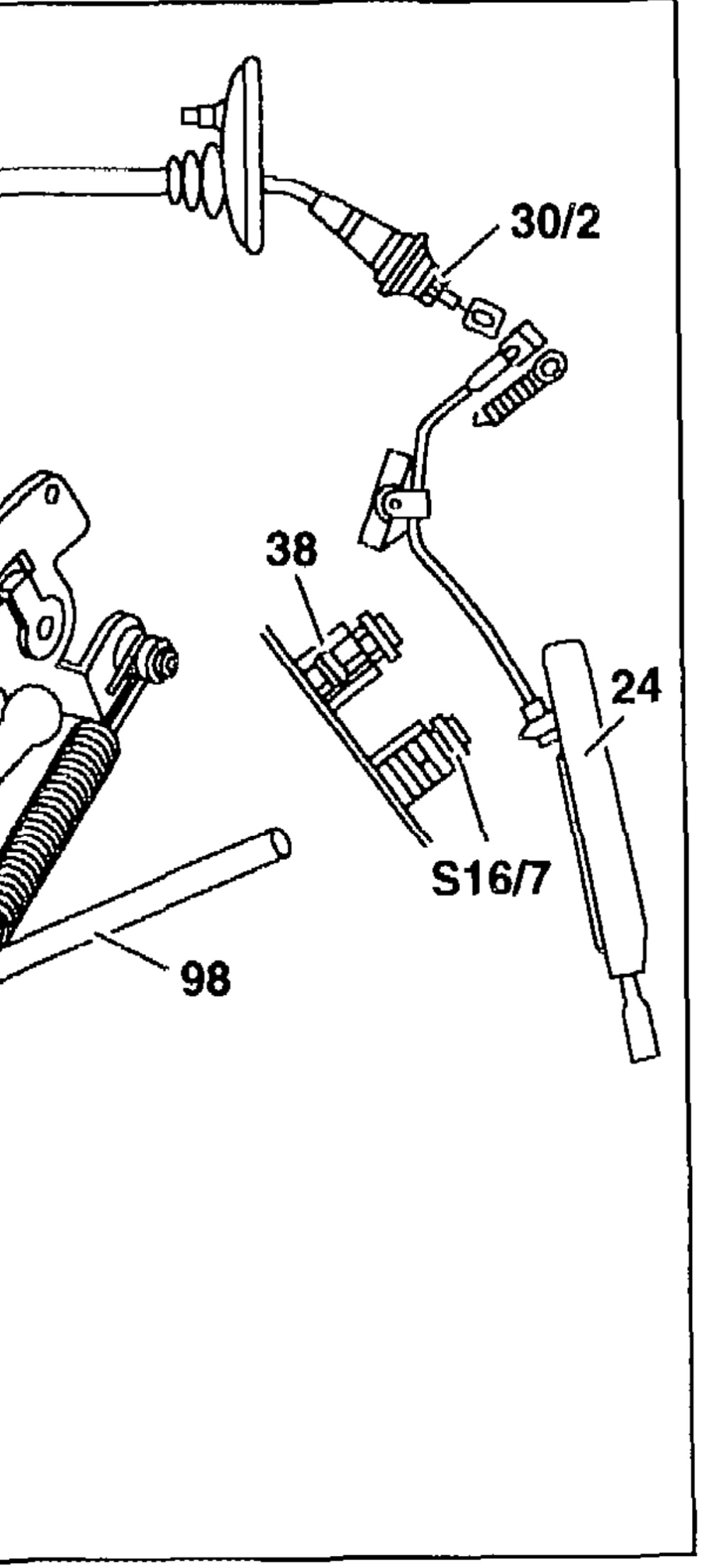
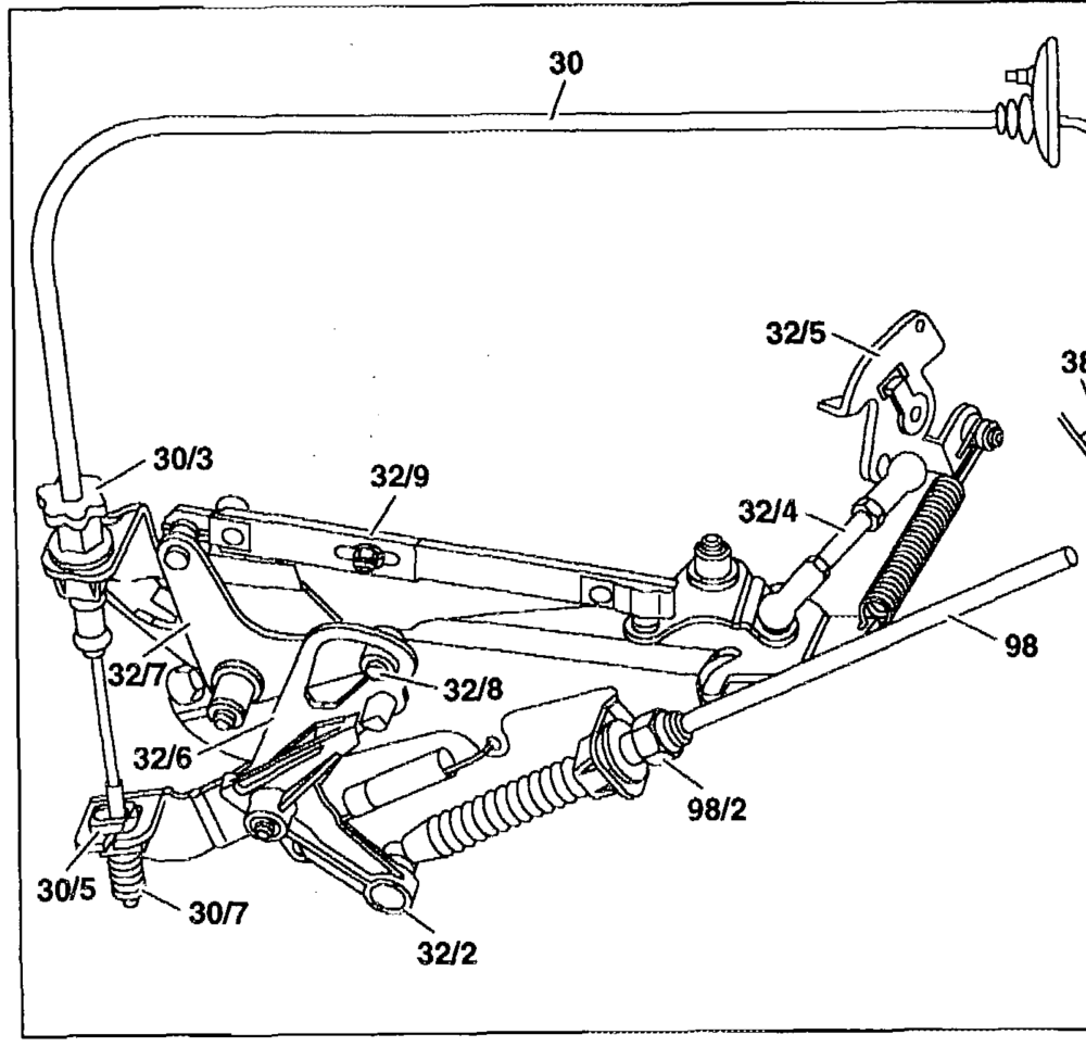
Engine 104
Shown on model 124 with automatic
transmission
24 Accelerator pedal
30 Accelerator control cable 30/2. Adjusting nut 30/3 Adjusting screw 30/5 Guide piece 30/7 Driver spring 32/2 Drag lever 32/4 Connecting rod 32/5‘ Bell crank 32/6 Fulcrum lever 32/7. Control lever 32/8 Roller 32/9 Connecting rod
38 Variable full throttle stop
98 Control pressure control cable 98/2 Adjusting screw $16/7 Kickdown switch, 2nd transmission mode
P30.10-0215–06
#41 AR30.10-P-1010D ie
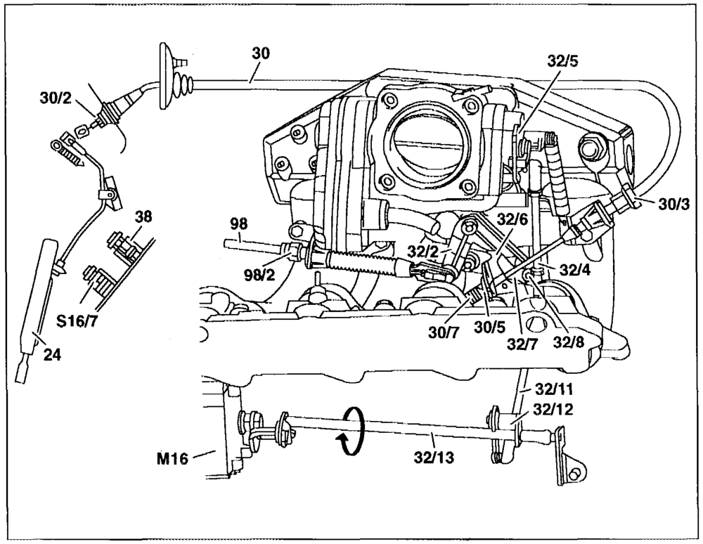
Engine 111
Shown on model 124 with automatic transmission
24 Accelerator pedal
30 Accelerator control cable 30/2. Adjusting nut 30/3 Adjusting screw 30/5 Guide piece 30/7 Driver spring 32/2 Drag lever 32/4 Connecting rod 32/5 Bell crank 32/6 =Fulcrum lever 32/7 Control lever 32/8 Roller 32/11 Connecting rod (cruise control only) 32/12 Drag lever (cruise control only) 32/13 Control shaft (cruise control only)
38 Variable full throttle stop
98 Control! pressure control cabie 98/2 Adjusting screw M16 Cruise control (CC) actuator (cruise control only) P30.10-0216-06 $16/7 Kickdown switch, 2nd transmission mode
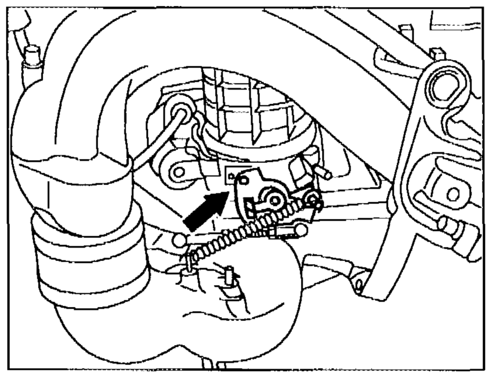
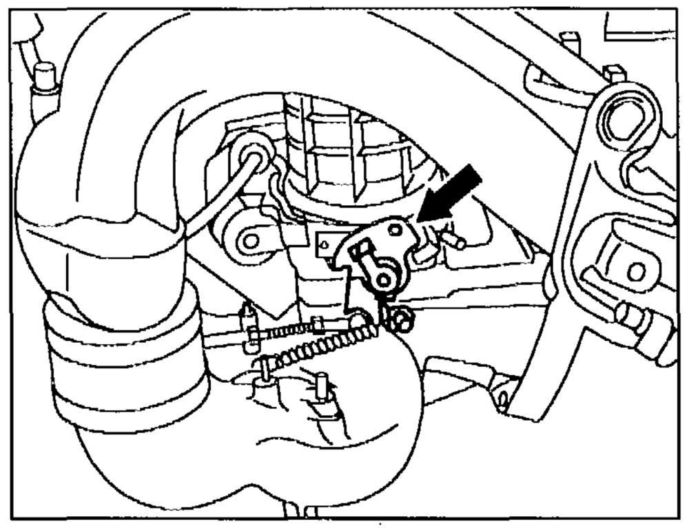
Left-hand illustration: closed throttle position (idle) stop (arrow) Shown on engine 104
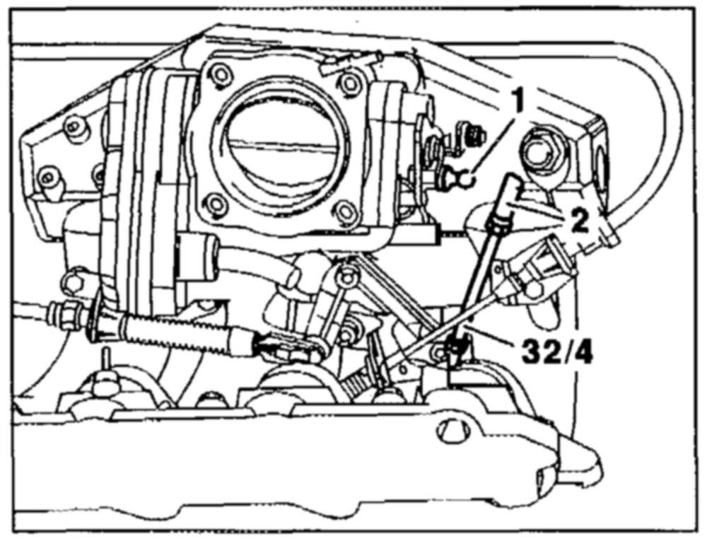
Right-hand illustration: full throttle stop (arrow) Shown on engine 104
P30.10-0217–01
Left-hand illustration: engine 111
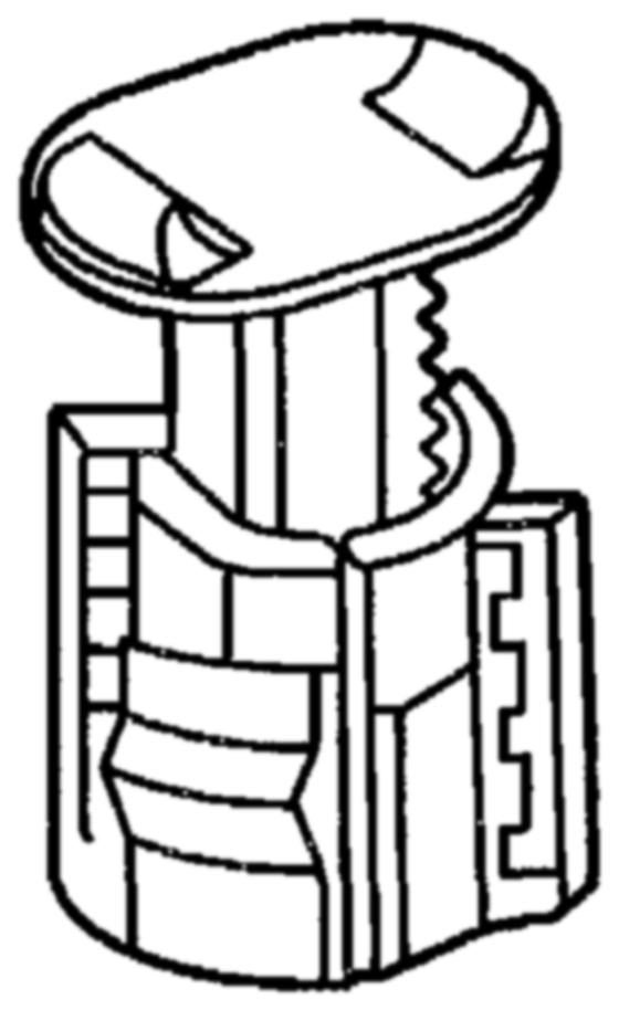
1 Ball pin
2 Ball socket 32/4 Connecting rod
Right-hand illustration:
38 Variable full throttle stop (in footwell)
P30.10-0222–01 P30.10-0219–01
#31 AR30.10-P-1010D
| Adjusting | ||
| Ignition: OFF | ||
| inspect connecting rods (32/4, 32/9) and accelerator control cable (30) to ensure they operate freely and are in proper condition | Replace parts, if necessary | |
| Check play between driver spring (30/7) and guide piece (30/5), adjust | There must be play between driver spring (30/7) and guide piece (30/5). Set with adjusting screw (30/3), if necessary | BE30.10-P-1001-01A |
| Detach connecting rod (32/4) at one end and check closed throttle position (idle) stop | Bell crank (32/5) must be resting against closed throttle position (idle) stop of idle speed control actuator | |
| Attach connecting rod (32/4) free of tension | Engine 104: connecting rod (32/4) must remain set to a fixed size. Measure between centers of ball sockets. | BE30.10-P-1002-01A |

Adjust connecting rod (32/4)
Engine 111:
BE30.10-P-1002-01A Position connecting rod (32/4) at ball pin free of tension (fig.). Shorten connecting rod (32/4) by turning ball socket (2) in 2 turns, attach and lock
Lil the adjustment of the connecting rod (32/4) must be performed very accurately. The microswitch for the idle speed control must be operated when doing this (closed)
#31 AR30.10-P-1010D
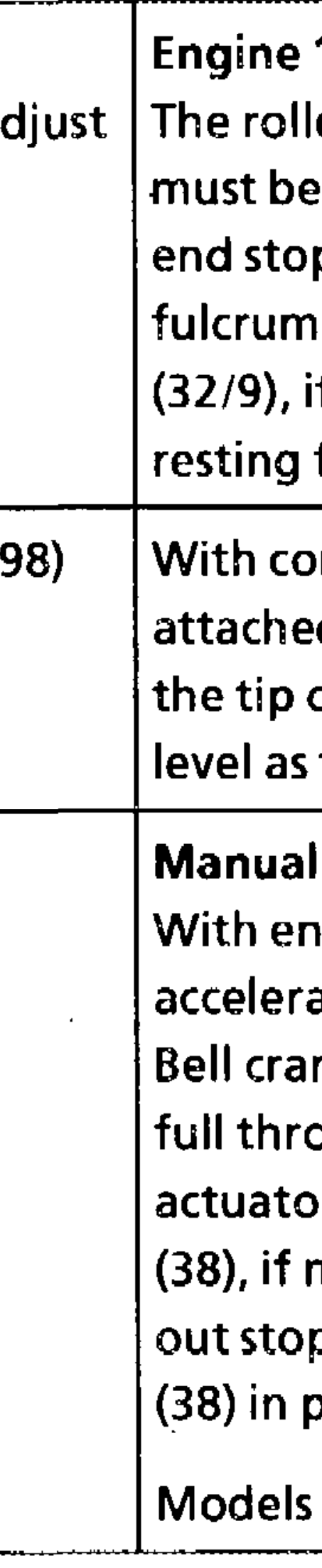
104: (32/8) in the control lever (32/7) resting free of tension against the of the fulcrum lever (32/6). Adjust lever (32/6) with connecting rod if necessary, so that roller (32/8) is free of tension against the end stop
control pressure contro} cable turn adjusting screw (98/2) until of drag lever (32/2) is at the same the tip of the fulcrum lever (32/6)
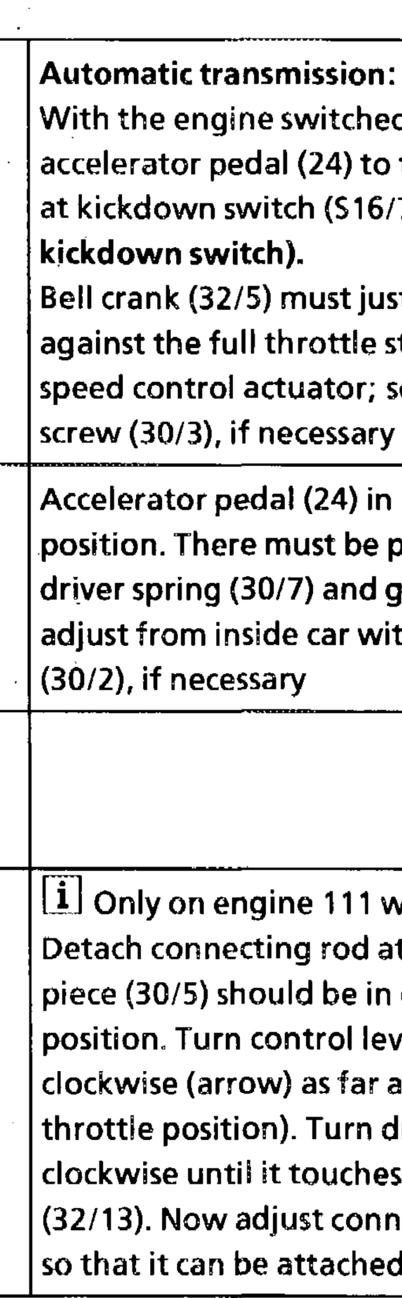
transmission: 7.1 engine switched off, depress pedal (24) to full throttle stop. (32/5) must be resting against throttie stop of idle speed control Release variabie full throttle stop necessary, by turning to the left. Pull pin slightly, lock full throttle stop position by turning to the right.
he BT
124, 129, 202 BT30.10-P-0003-01A

#31 AR30.10-P-1010D
off, depress full throttle stop
(do not operate
be resting stop of the idle set with adjusting
Checking idle speed adjustment at chassis
idle speed
end, adjusting
play between guide piece (30/5); adjusting nut
Grease accelerator control cable (30) between end piece and guide piece (30/5) with anti-corrosion grease
Adjust connecting rod (32/11) with cruise control. one side. Guide closed throttle (32/7) as the stop (closed drag lever (32/12) the contral shaft connecting rod (32/11) free of stress.
# J1 AR30.10-P-1010D
Test values of accelerator control
| Designation | Engine 104 | Engine 111 | |
| Play of accelerator control cable between driver spring and guide piece at fulcrum lever | mm | 0.5–1.0 | 0.5–1.0 |
| Length of connecting rod to bell crank (fixed dimension) | mm | 84 | – |
Repair product
Number Designation Order number
Anti-corrosion grease BROO.45-Z1007-064 – 001 989 37 51 10