Replacing and riveting timing chain
WIS 05-3200
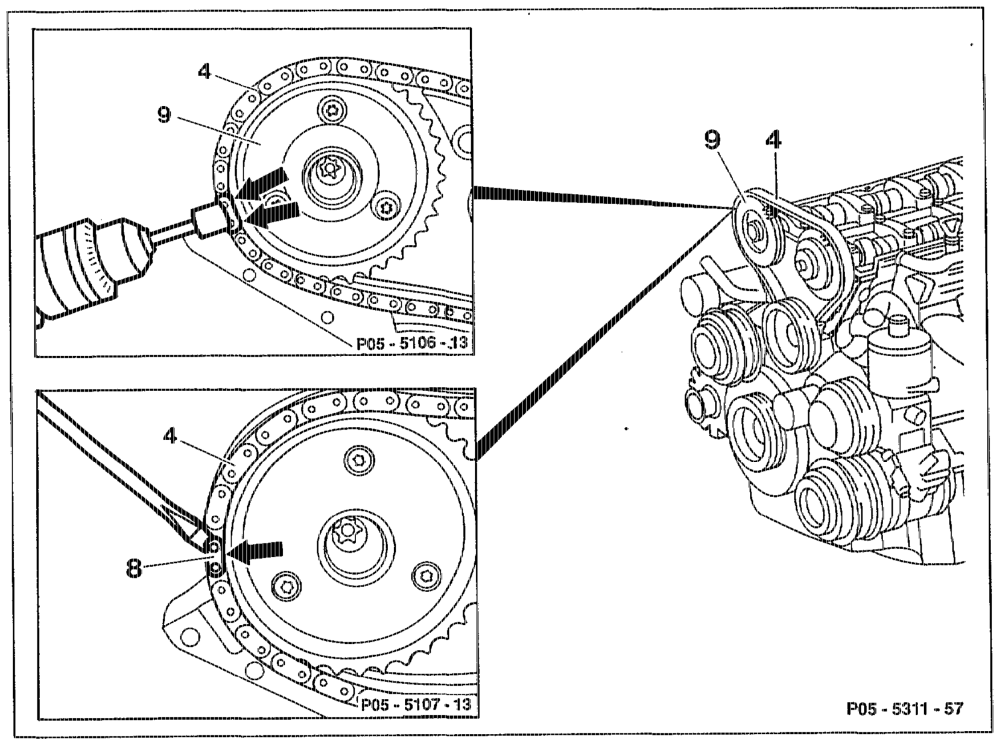
Preceding work: Spark plugs removed (AP15.00-1580CA)
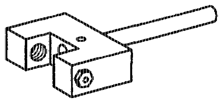
chain tensioner oo… eee ee eee rs remove (05-3100). Engines with HT distributor: ………. eee remove front cover and topguicde rail (01-2120). Engines without HT distributor: …. see e wees remove top guide rail (05-3400). Chain box… cee eee eee see eee cover over with a clean cloth. Chain pin (arrows) of timing chain (4) at exhaust camshaft sprocket (9) ……. vee eee vee grind open (arrows), separate with chain separating tool 602 589 02 33 00 and thrust spindle 602 589 04 63 00 (@ 2.9 mrn). Plate (8) of timing chain (4) ………….00. prise off with screwdriver. Ground-open double link ………. seve : press out.
ohn §=RA 05.1225-3200/1
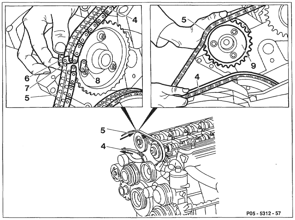
New timing chain (5) ………..4. seen eee connect to old tirning chain (4) with riveted link (6) and centre plate (7) (thickness 1.6 mm) and ground-open outer plate (8). Crankshaft see eens seen e nee eee eee rotate with wrench socket insert in direction of rotation of engine. Pay attention to different lengths of timing chains: Engine 104.980/981 130 links Engine 104.94/99 126 links New separated timing chain (5) …………. pull in. Timing Chain… ee ee ee hold meshed at exhaust camshaft sprocket (9) by hand when pulling in. Bottom free end (4) of timing chain) ………. pull out of chain box. Crankshaft ……. tee eee eee eee o rotate sufficiently until the end of the new timing chain can be connected with the riveted link.
tiie §=RA 05.1225-3200/2
New timing chain (6) «2.2… 0. cc ee eee eee connect to inserted link (6) and centre plate (7).
Note
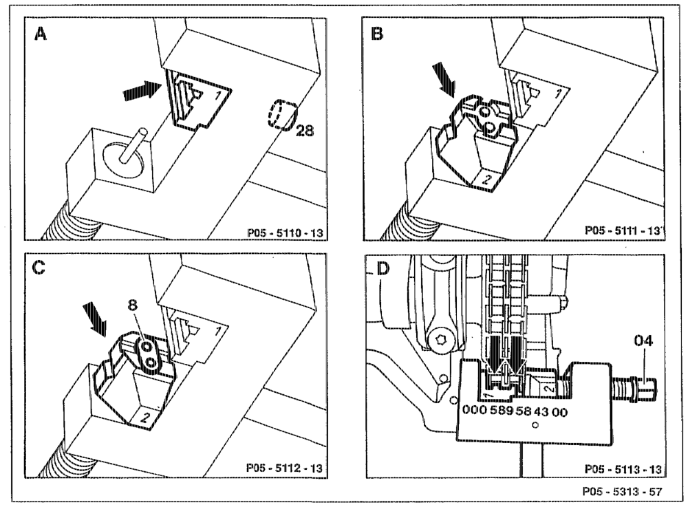
Riveted links of the IWIS version part no. 000 997 22 98 should be matched to the IWIS timing chain and riveted links of the Renold version should be matched to the Renold tirning chain. The identifications are stamped in each case on the outer plates of the timing chain.
Jaw for duplex roller chain with digit? …….. insert into pressing-on tool and screw on with screw (28) (Fig. A). Moving thrust piece for simplex roller chain with the digit2 cee eee eet eee nes insert into pressing-on tool (Fig. B).
aniige = RA 05. 1225-3200/3
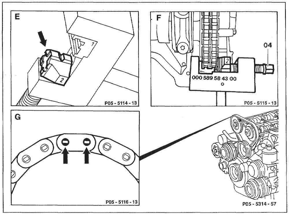
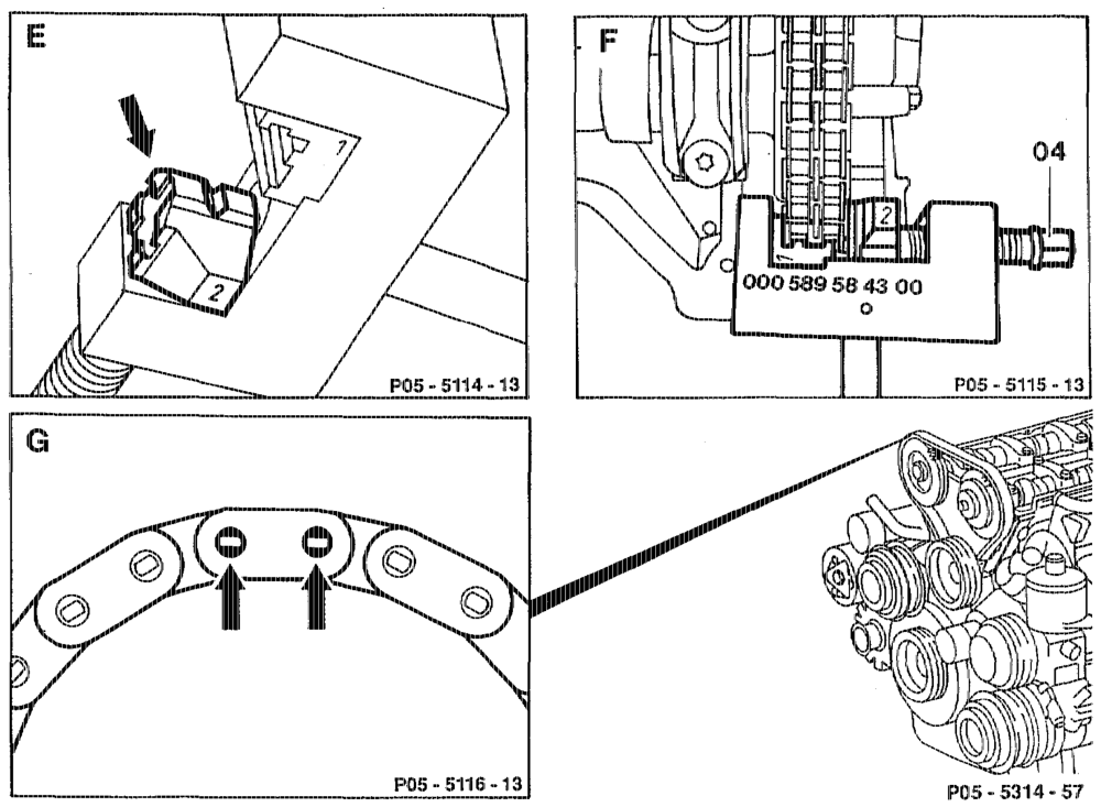
Outer plate (8) of 1.2 insert into moving thrust piece (Fig. C). Webs (arrows) fit onto rollers at riveted link (Fig. D). Spindle (04) screw in until tight resistance felt (Fig. D). When screwing in, ensure that the pins of the riveted link are inserted into the holes of the outer plate (8). Pressing-on tool take off.
turn over (riveting profile) (Fig. E). Moving thrust piece with the digit 2 Pressing-on tool position exactly over middle of pin (Fig. F). Spindle (04) to 30 Nm tighten (Fig. F). Pins of inserted link (6) rivet individually. inspect, re-rivet if necessary (Fig. G). Riveting
ote RA 05.1225-3200/4
Basic position of camshafts ………….005 adjust (05-2240). Front cover and top guide rail install (01-2120). Chain tensioner …….. seen sence eee install (05-3100). Basic position of camshafts …………000check (05-2230).
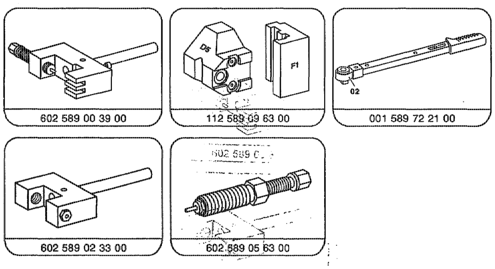
Special tools
otis §=RA 05.1225-3200/5