Removing and installing guide sprocket, engine 104.98
WIS 05-4400
‘cunenspanuaenaneuosennsuvqsuensnqaaenauvanenvannanayessnqaunananneusneunseenseusesnnesususnnaenneerseuensnnatsesendaedhaonssursareneerssusseunaeunseneauncecnnsssianeneeuseuscsuncueaeunaunnennansuansanaensenseeHRaSHSSHSEEERGEEROECuaNnnbenen?
Operation no. of operation texts and work units or standard texts and flat rates: 05-8051–8052
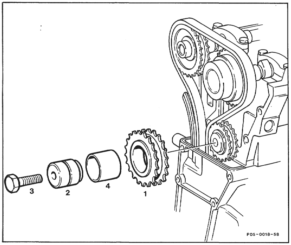
Front cover ………000ween wee eas remove, install (01-2120). Inlet camshaft dene e ee eee rotate in opposite direction of rotation until timing chain slackened. Front side of guide sprocket …… vee ene mark because of direction of rotation. Bolt (3) „left-hand thread” ……………. unscrew, screw in, tighten 35 Nm (step 3). Guide sprocket (1) with bearing journal 2) tenes take off, fit on (step 4).
athe RA 05.1224-4400/1
Removing and installing
1 Rotate inlet carnshaft in opposite direction of rotation until timing chain at guide sprocket is slackened.
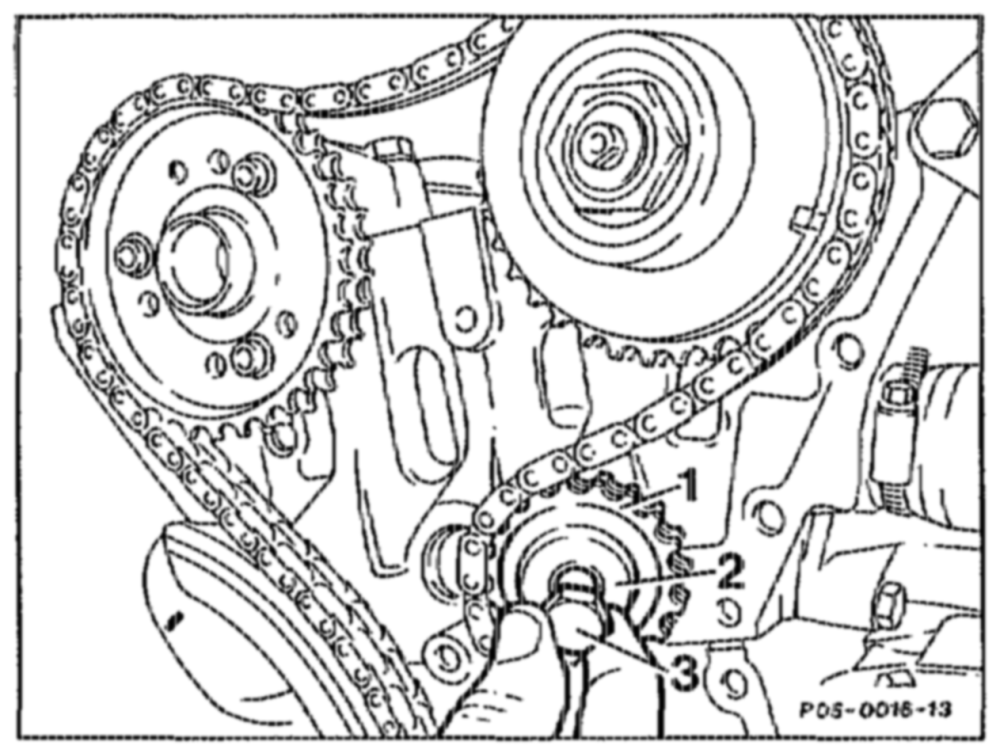
2 Mark front side guide sprocket. A used guide sprocket should rotate in the same direction.
3 Unscrew bolt (3) “left-hand thread”, screw in and tighten. Tightening torque 35 Nn.
4 Take off guide sprocket (1) together with bearing journal (2). Oil bearing bush and fit on.
wtih =RA 05.1224-4400/2