Coolant circuit
WIS 20-0050
aunennauuaeuaaucnecuqaenessusaennaducceuenanunnestent,
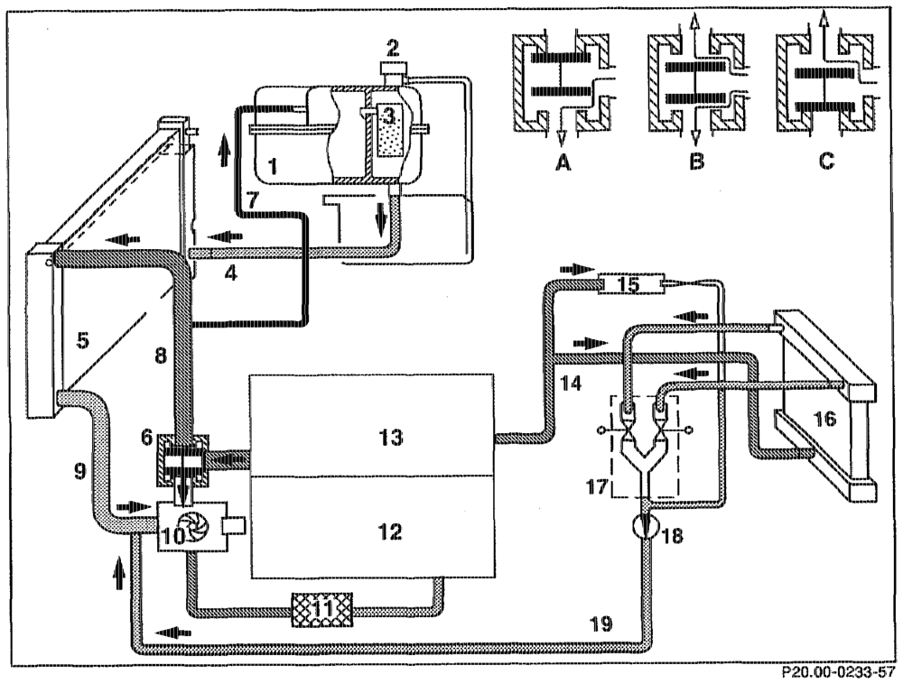
1 Expansion reservoir W Oil-to-coolant heat exchanger
2 Pressure cap: 12 Crankcase_ Model 210 two-stage pressure cap 13 Cylinder head
3 Integrated silica gel reservoir 14, Heating system feed pipe
4 Filling pipe 16 Windscreen wiper water heater
5 Cross-flow radiator 16 Heating system heat exchanger
6 Thermostat 7 Duo pulsed valve
7 Vent pipe 18 Circulation pump é From engine to radiator 19 Heating system retum pipe
9 From radiator to engine
10 Coolant pump
otis FAA 20.1234-0050/1
The coolant flows from the cylinder head through the coolant pump to the crankcase.
B Mixed mode The coolant flows partly through the radiator and partly through the coolant pump to the crankcase.
C Cooling mode The coolant flows through the radiator and the coolant pump to the crankcase.
whine §=RA 20.1234-0050/2