Checking, correcting setting of TOC sensor
WIS 03-3450
Preceding work: Operation no. of operation texts and work units or standard texts Viscous fan shroud removed (20-3120). and flat rates Poly V-belt removed (13-1200). 03-1101 Cylinder head cover removed (01-0500).
Checking setting of TOC sensor
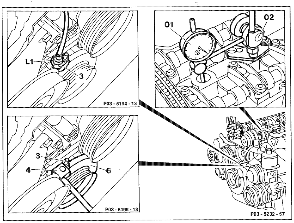
Piston of cylinder 1 ….. teen eee ween ee turn to 10° before ignition TDC. Spark plug of cylinder 1 2.0… ee cee ee eee remove, install. TDC sensor (L1) 6… seen tee eee unbolt, bolt on. TDC sensor (L1) cece eee eee remove from adjusting slide (3). Dial gauge holder (02) 136 589 042100 ….. . install.
utiie §=RA 03.1224-3450/1
Dial gauge (01) and extension (length 155 mr) insert into cial gauge holder (02) with 4 mm preload. Crankshaft rotate in direction of rotation of angine and set TDC on cylinder 1 with dial gauge (01). Large pointer of dial gauge (01) zero. Crankshaft rotate in direction of rotation of engine until dial gauge has moved back by the value, see table „piston travel” (20° after TDC of cylinder 1). Locating device (4) 119 58900 2100 ……… insert into adjusting slide (3). Locating device (4) 119 589 00 21 00 must engage over measuring pin on vibration damper (6).
Correcting setting of TDC sensor
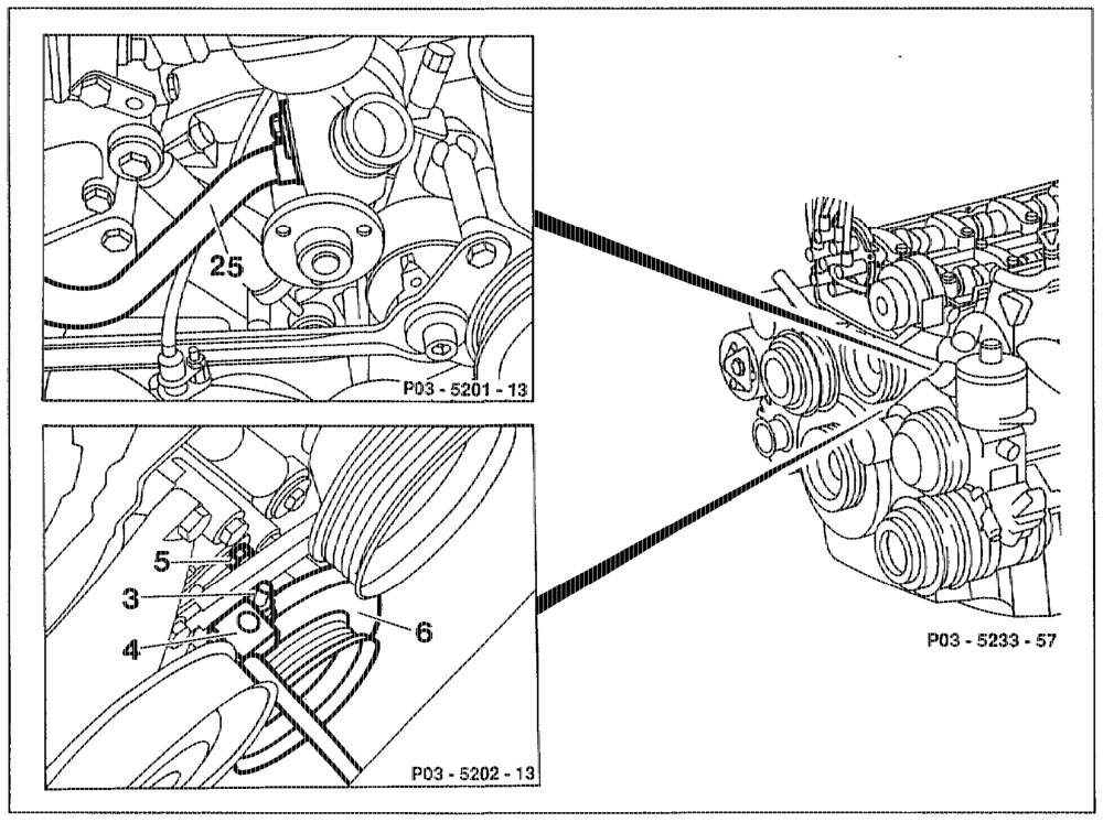
wthin RA 039.1224~3450/2
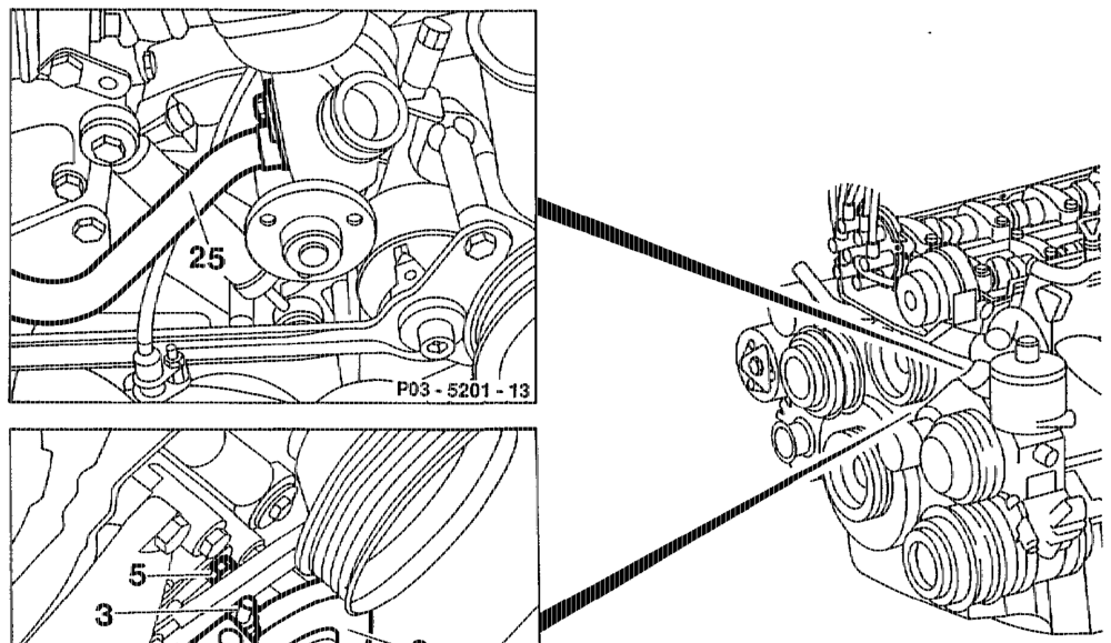
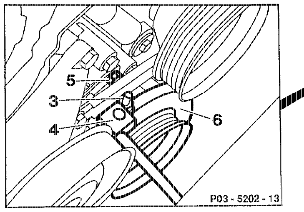
Engine 104.98: ……. wee See eee aeuaeeeee open cap of cooling system (release pressure). Engine 104.98: ………. tee see eee remove heating water return line (25), install; replace seal. Engine 104.98: ……. vee wee sence ee eee plug opening of coolant pump. Bolt (5) of adjusting slide (3) teense enee see slacken. Adjusting slide (3) …….. bees ee nen eee move until locating device engages over measuring pin (4) on vibration damper (6). see eee ene tighten. Bolt (5) ….. see eens Engine 104.98: ….. wee sews enews eres pour in coolant (20-0100). Engine 104.98: seen ween eee se check cooling system for leaks (20-0170).

Piston travel with crankshaft In position 20° after TOC of cylinder 1 in mm
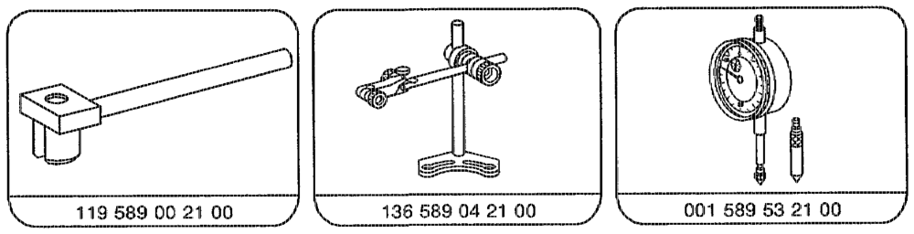
Special tools
atime §=RA 03.1224-3450/3
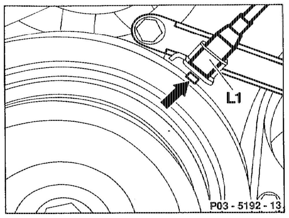
Notes The TDC sensor (L1) with bracket is attached to the tirning case cover. The measuring pin (arrow) in the vibration damper must be postioned in the middle below the TDG sensor (L1) at 20° after TDC in cylinder 1.
The setting of the TDC sensor must be checked and corrected, as necessary: ® When replacing the crankshaft or the vibration damper. ® When replacing the timing case cover. @ When adding parts to short engines.
With the cylinder head removed, attach a dial gauge holder to the crankcase and place dial gauge pin vertically onto the piston crown.
atihijn RA 03.1224-3450/4