Removing, installing and adjusting chassis accelerator control
WIS 30-0320
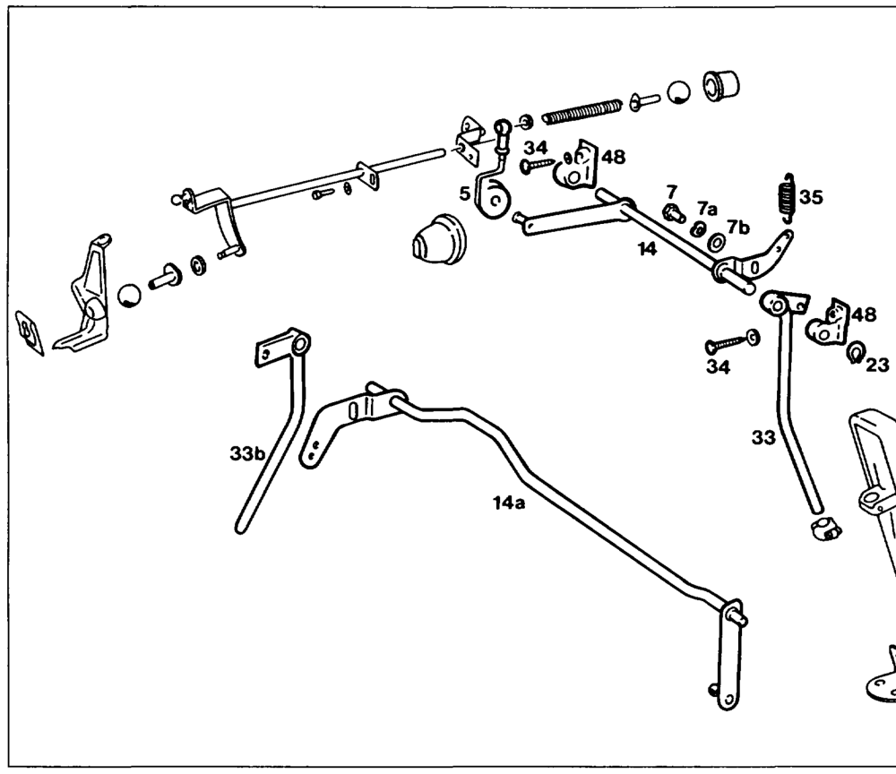
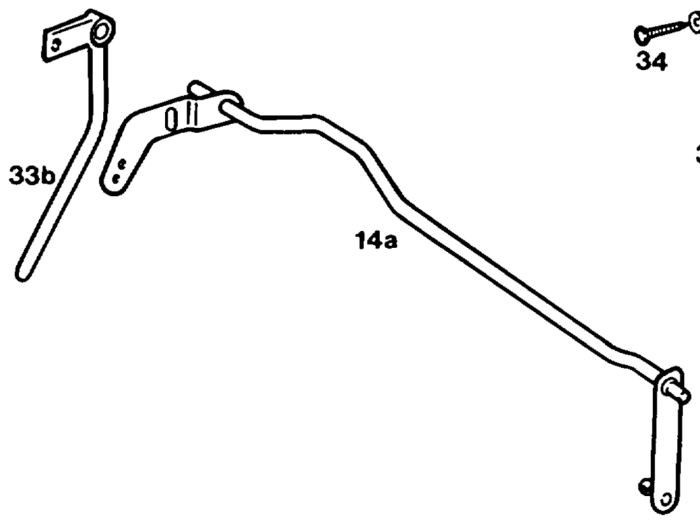
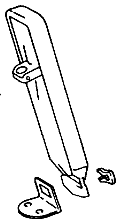
P30-0124-57A
33 LHD accelerator pedal lever
14 LHD accelerator contro! shaft 33b RHD accelerator pedal lever 14a RHD accelerator control shaft
remove, install (30-1321). Accelerator pedal ……………0. Footwell trim …………..220006 remove, install. press off lever of accelerator contro! shaft, fit Push rod (5) with damper ring …….. on. Pay attention to note. remove, install (83-100). Heater box ………-..—0–000Return spring (35) detach, attach. Screws (34) ……….202 20002 eee unscrew, screw in. Fire wall bearing (48) push out upward, install.
wie §=RA 30.1142-0320/1
Accelerator control shaft (14, 14a) ……….. take off with bearing, fit on.
Note Grease the bearing points and also the ball sockets of the accelerator control with anticorrosion grease 000 989 87 51 10. Circlip (23) 2.0… ee eee ee eee pull off, fit on. Bolt (7), corrugated washer (7a), washer (7b) … unscrew, screw in. Accelerator pedal lever (33, 33b) Lee eee eee pull off, fit on. Accelerator control linkage wee ee ee eee eee adjust (30-1010).
Note
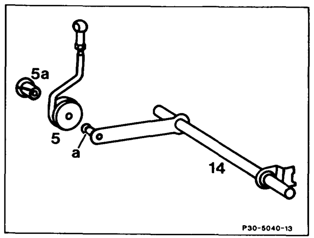
Since 02/81 the push rod (5) is fitted with a bush (5a) to the accelerator control shaft (14, 14a). Retrofitting is possible as follows: – Lightly grease button pin (a) with anticorrosion grease 000 989 87 51 10. – Insert bush (5a) into push rod (5) and press push rod onto button pin (a). Ensure the bearing bush is correctly seated.